Plug and Play ISA
Specification
Version 1.0a
May 5, 1994
�
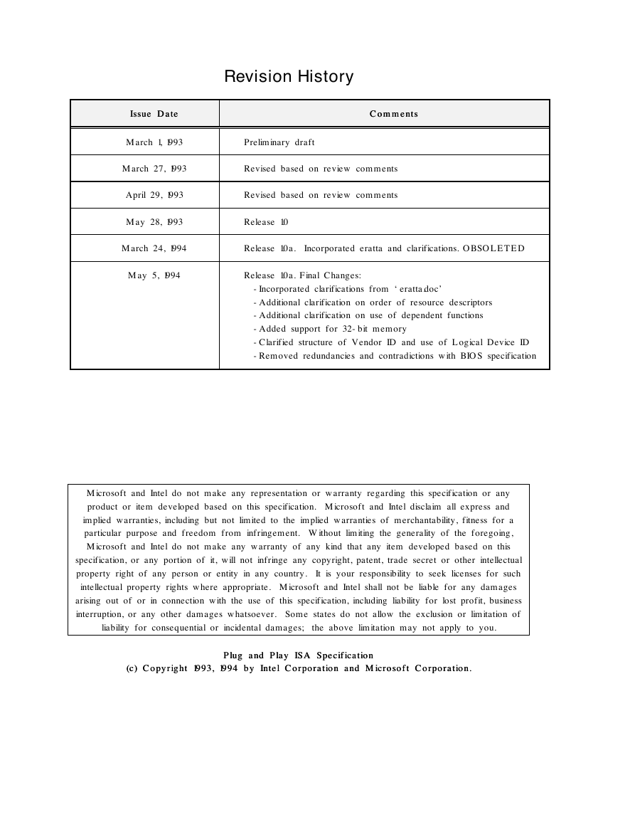
Revision History
Issue Date
Issue Date
Comments
Comments
March 1, 1993
Preliminary draft
March 27, 1993
Revised based on review comments
April 29, 1993
Revised based on review comments
May 28, 1993
Release 1.0
March 24, 1994
Release 1.0a. Incorporated eratta and clarifications. OBSOLETED
May 5, 1994
Release 1.0a. Final Changes:
-Incorporated clarifications from ‘eratta.doc’
-Additional clarification on order of resource descriptors
-Additional clarification on use of dependent functions
-Added support for 32-bit memory
-Clarified structure of Vendor ID and use of Logical Device ID
-Removed redundancies and contradictions with BIOS specification
Microsoft and Intel do not make any representation or warranty regarding this specification or any
product or item developed based on this specification. Microsoft and Intel disclaim all express and
implied warranties, including but not limited to the implied warranties of merchantability, fitness for a
particular purpose and freedom from infringement. Without limiting the generality of the foregoing,
Microsoft and Intel do not make any warranty of any kind that any item developed based on this
specification, or any portion of it, will not infringe any copyright, patent, trade secret or other intellectual
property right of any person or entity in any country. It is your responsibility to seek licenses for such
intellectual property rights where appropriate. Microsoft and Intel shall not be liable for any damages
arising out of or in connection with the use of this specification, including liability for lost profit, business
interruption, or any other damages whatsoever. Some states do not allow the exclusion or limitation of
liability for consequential or incidental damages; the above limitation may not apply to you.
(c) Copyright 1993, 1994 by Intel Corporation and Microsoft Corporation.
(c) Copyright 1993, 1994 by Intel Corporation and Microsoft Corporation.
Plug and Play ISA Specification
Plug and Play ISA Specification
�
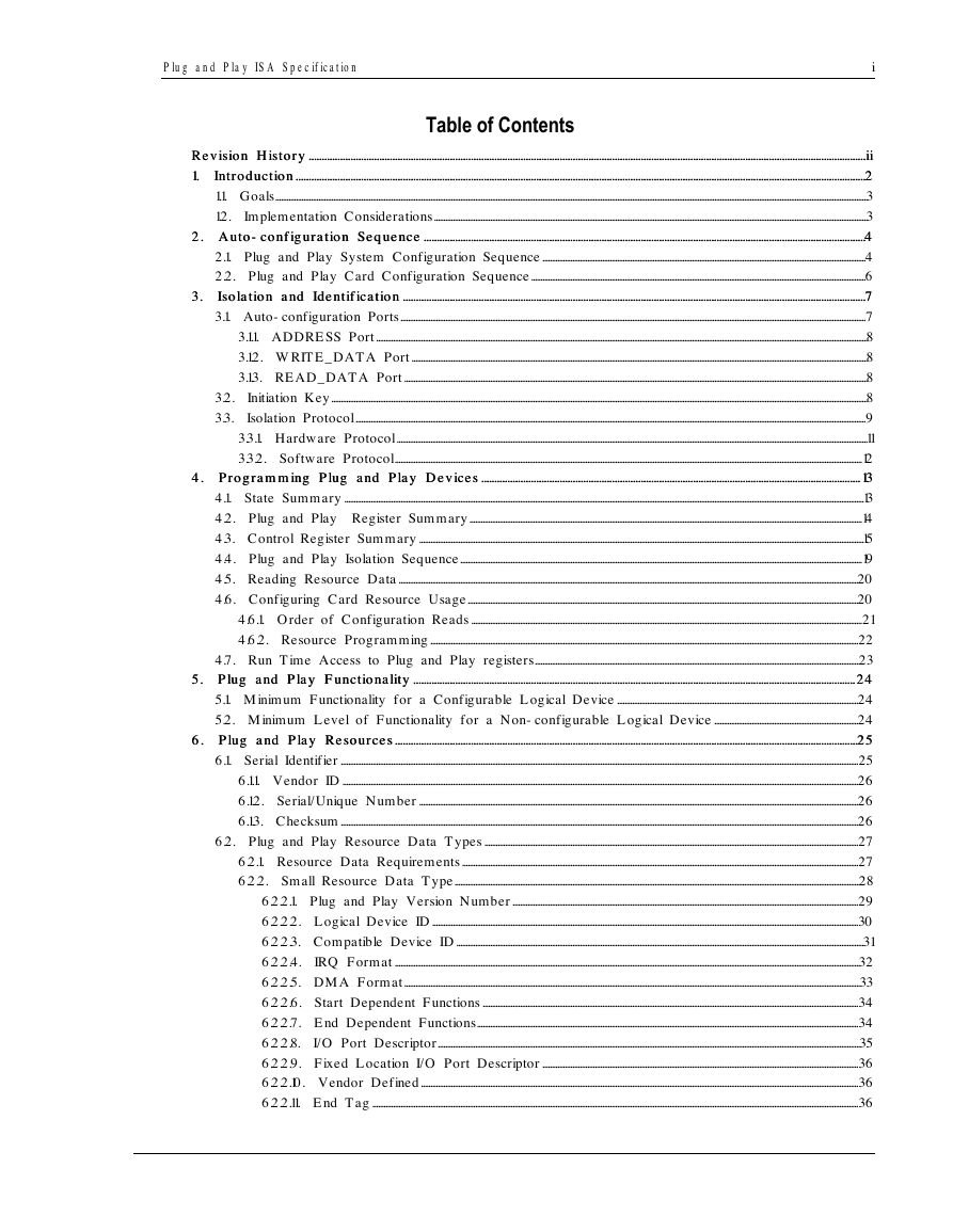
4. Programming Plug and Play Devices
4. Programming Plug and Play Devices ................................
5. Plug and Play Functionality
5. Plug and Play Functionality ................................
................................................................
Plu g a n d Pla y ISA S p e cific a tio n
i
Table of Contents
Revision History
Revision History ................................
1. Introduction
1. Introduction ................................
2. Auto
2. Auto-configuration Sequence
3. Isolation and Identification
3. Isolation and Identification ................................
................................................................
................................................................
................................................................
................................................................
.................................................
................................................................
................................................................
................................................................
................................................................
................................................................
................................................................
................................................................
................................................................
................................................................
................................................................
................................................................
................................................................
................................................................
................................................................
................................................................
................................................................
................................................................
-configuration Sequence ................................
.....................................................
..................... iiii
..........................................................
..........................22
1.1. Goals.............................................................................................................................................................................................................................................................................................................................3
1.2. Implementation Considerations........................................................................................................................................................................................................................................3
.........................................
.........44
2.1. Plug and Play System Configuration Sequence.............................................................................................................................................................................4
2.2. Plug and Play Card Configuration Sequence...................................................................................................................................................................................6
.................................................
.................77
3.1. Auto-configuration Ports.........................................................................................................................................................................................................................................................7
3.1.1. ADDRESS Port.......................................................................................................................................................................................................................................................................8
3.1.2. WRITE_DATA Port....................................................................................................................................................................................................................................................8
3.1.3. READ_DATA Port........................................................................................................................................................................................................................................................8
3.2. Initiation Key...............................................................................................................................................................................................................................................................................................8
3.3. Isolation Protocol.................................................................................................................................................................................................................................................................................9
3.3.1. Hardware Protocol............................................................................................................................................................................................................................................................11
3.3.2. Software Protocol..........................................................................................................................................................................................................................................................12
................. 1313
4.1. State Summary......................................................................................................................................................................................................................................................................................13
4.2. Plug and Play Register Summary..................................................................................................................................................................................................................14
4.3. Control Register Summary..............................................................................................................................................................................................................................................15
4.4. Plug and Play Isolation Sequence.......................................................................................................................................................................................................................19
4.5. Reading Resource Data......................................................................................................................................................................................................................................................20
4.6. Configuring Card Resource Usage.................................................................................................................................................................................................................20
4.6.1. Order of Configuration Reads.................................................................................................................................................................................................................21
4.6.2. Resource Programming.....................................................................................................................................................................................................................................22
4.7. Run Time Access to Plug and Play registers..............................................................................................................................................................................23
......... 2424
5.1. Minimum Functionality for a Configurable Logical Device.................................................................................................................................24
5.2. Minimum Level of Functionality for a Non-configurable Logical Device.............................................................................24
.................2525
6.1. Serial Identifier.....................................................................................................................................................................................................................................................................................25
6.1.1. Vendor ID....................................................................................................................................................................................................................................................................................26
6.1.2. Serial/Unique Number...........................................................................................................................................................................................................................................26
6.1.3. Checksum.....................................................................................................................................................................................................................................................................................26
6.2. Plug and Play Resource Data Types........................................................................................................................................................................................................27
6.2.1. Resource Data Requirements....................................................................................................................................................................................................................27
6.2.2. Small Resource Data Type.........................................................................................................................................................................................................................28
6.2.2.1. Plug and Play Version Number.........................................................................................................................................................................................29
6.2.2.2. Logical Device ID....................................................................................................................................................................................................................................30
6.2.2.3. Compatible Device ID..........................................................................................................................................................................................................................31
6.2.2.4. IRQ Format.........................................................................................................................................................................................................................................................32
6.2.2.5. DMA Format....................................................................................................................................................................................................................................................33
6.2.2.6. Start Dependent Functions.........................................................................................................................................................................................................34
6.2.2.7. End Dependent Functions............................................................................................................................................................................................................34
6.2.2.8. I/O Port Descriptor..................................................................................................................................................................................................................................35
6.2.2.9. Fixed Location I/O Port Descriptor.........................................................................................................................................................................36
6.2.2.10. Vendor Defined..........................................................................................................................................................................................................................................36
6.2.2.11. End Tag....................................................................................................................................................................................................................................................................36
................................................................
................................................................
................................................................
.........................................
6. Plug and Play Resources
6. Plug and Play Resources ................................
................................................................
................................................................
................................................................
................................................................
.................................................
�
ii
Plu g a n d Pla y ISA S p e cific a tio n
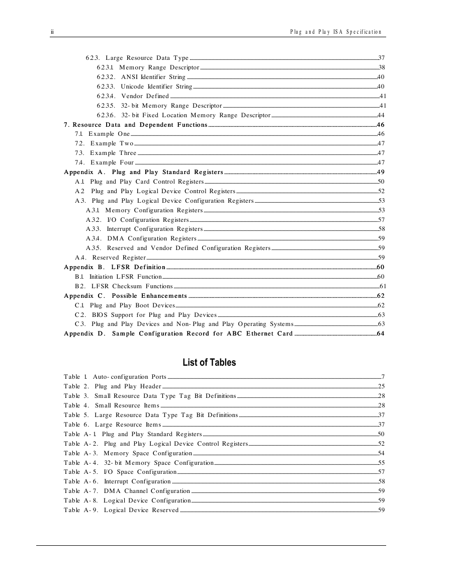
Appendix A. Plug and Play Standard Registers
Appendix A. Plug and Play Standard Registers ................................
7. Resource Data and Dependent Functions
7. Resource Data and Dependent Functions................................
................................................................
................................................................
................................................................
.........................................
6.2.3. Large Resource Data Type.......................................................................................................................................................................................................................37
6.2.3.1. Memory Range Descriptor...........................................................................................................................................................................................................38
6.2.3.2. ANSI Identifier String.........................................................................................................................................................................................................................40
6.2.3.3. Unicode Identifier String..................................................................................................................................................................................................................40
6.2.3.4. Vendor Defined..............................................................................................................................................................................................................................................41
6.2.3.5. 32-bit Memory Range Descriptor..................................................................................................................................................................................41
6.2.3.6. 32-bit Fixed Location Memory Range Descriptor.........................................................................................................................44
.........4646
7.1. Example One.........................................................................................................................................................................................................................................................................................46
7.2. Example Two.....................................................................................................................................................................................................................................................................................47
7.3. Example Three.................................................................................................................................................................................................................................................................................47
7.4. Example Four....................................................................................................................................................................................................................................................................................47
............................ 4949
A.1. Plug and Play Card Control Registers.....................................................................................................................................................................................................50
A.2 Plug and Play Logical Device Control Registers.................................................................................................................................................................52
A.3. Plug and Play Logical Device Configuration Registers.............................................................................................................................................53
A.3.1. Memory Configuration Registers.......................................................................................................................................................................................................53
A.3.2. I/O Configuration Registers......................................................................................................................................................................................................................57
A.3.3. Interrupt Configuration Registers.......................................................................................................................................................................................................58
A.3.4. DMA Configuration Registers.............................................................................................................................................................................................................59
A.3.5. Reserved and Vendor Defined Configuration Registers.........................................................................................................................59
A.4. Reserved Register.......................................................................................................................................................................................................................................................................59
...........6060
B.1. Initiation LFSR Function.....................................................................................................................................................................................................................................................60
B.2. LFSR Checksum Functions..........................................................................................................................................................................................................................................61
......................... 6262
C.1. Plug and Play Boot Devices......................................................................................................................................................................................................................................62
C.2. BIOS Support for Plug and Play Devices......................................................................................................................................................................................63
C.3. Plug and Play Devices and Non-Plug and Play Operating Systems...............................................................................................63
......................................6464
................................................................
................................................................
................................................................
................................................................
................................................................
...........................................
................................................................
................................................................
................................................................
.........................................................
................................................................
................................................................
............................................................
Appendix B. LFSR Definition
Appendix B. LFSR Definition ................................
Appendix C. Possible Enhancements
Appendix C. Possible Enhancements ................................
Appendix D. Sample Configuration Record for ABC Ethernet Card
Appendix D. Sample Configuration Record for ABC Ethernet Card ................................
List of Tables
Table 1. Auto-configuration Ports...................................................................................................................................................................................................................................................7
Table 2. Plug and Play Header.....................................................................................................................................................................................................................................................25
Table 3. Small Resource Data Type Tag Bit Definitions.................................................................................................................................................................28
Table 4. Small Resource Items........................................................................................................................................................................................................................................................28
Table 5. Large Resource Data Type Tag Bit Definitions...............................................................................................................................................................37
Table 6. Large Resource Items......................................................................................................................................................................................................................................................37
Table A-1. Plug and Play Standard Registers.......................................................................................................................................................................................................50
Table A-2. Plug and Play Logical Device Control Registers...................................................................................................................................................52
Table A-3. Memory Space Configuration..................................................................................................................................................................................................................54
Table A-4. 32-bit Memory Space Configuration...........................................................................................................................................................................................55
Table A-5. I/O Space Configuration....................................................................................................................................................................................................................................57
Table A-6. Interrupt Configuration...........................................................................................................................................................................................................................................58
Table A-7. DMA Channel Configuration....................................................................................................................................................................................................................59
Table A-8. Logical Device Configuration....................................................................................................................................................................................................................59
Table A-9. Logical Device Reserved.................................................................................................................................................................................................................................59
�
Plu g a n d Pla y ISA S p e cific a tio n
iii
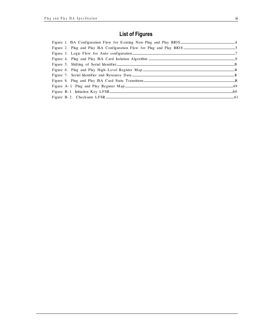
List of Figures
Figure 1. ISA Configuration Flow for Existing Non-Plug and Play BIOS............................................................................................................4
Figure 2. Plug and Play ISA Configuration Flow for Plug and Play BIOS......................................................................................................5
Figure 3. Logic Flow for Auto-configuration...........................................................................................................................................................................................................7
Figure 4. Plug and Play ISA Card Isolation Algorithm...........................................................................................................................................................................9
Figure 5. Shifting of Serial Identifier.......................................................................................................................................................................................................................................10
Figure 6. Plug and Play High-Level Register Map....................................................................................................................................................................................14
Figure 7. Serial Identifier and Resource Data.........................................................................................................................................................................................................16
Figure 8. Plug and Play ISA Card State Transitions...................................................................................................................................................................................18
Figure A-1. Plug and Play Register Map.....................................................................................................................................................................................................................49
Figure B-1. Initiation Key LFSR...................................................................................................................................................................................................................................................60
Figure B-2. Checksum LFSR.............................................................................................................................................................................................................................................................61
�
�
Plu g a n d Pla y ISA S p e cific a tio n
1
Abstract
This specification presents a mechanism to provide automatic configuration capability to In d u s t ry St a n d a r d
Ar c hite c t u r e (ISA) cards thus enabling full Plug and Play in the PC. The essential elements of Plug and Play
ISA are:
•
•
•
•
Isolate the ISA card
Read the card's resource data
Identify the card and configure its resources
Locate a driver for the card
The mechanism has the flexibility to allow cards to come up either inactive or active. Cards required to
participate in the boot process typically come up active. Information that identifies the card and describes the
system resources which are requested by the card, such as memory and I/O space, DMA channel, and
interrupt level supported is maintained in a standard read-only format. This allows the Plug and Play
software to identify system resource usage, arbitrate conflicts, and, optionally, re-configure a card. This
process is done automatically at every hard reset of the system. Plug and Play ISA cards will inter-operate
with standard ISA cards in a fully compatible manner.
Possible BIOS extensions required to support Plug and Play ISA cards are also discussed in this specification.
However, user interface issues for installation of device drivers are not addressed.
�
2
Plu g a n d Pla y ISA S p e cific a tio n
1. Introduction
The ISA bus is the most popular expansion standard in the PC industry. The bus architecture requires the
allocation of memory and I/O address spaces, DMA channels and interrupt levels among multiple ISA cards.
However, the ISA interface has no defined hardware or software mechanism for allocating these resources.
As a result, configuration of ISA cards is typically done with “jumpers” that change the decode maps for
memory and I/O space and steer the DMA and interrupt signals to different pins on the bus. Further,
system configuration files may need to be updated to reflect these changes. Users typically resolve sharing
conflicts by referring to documentation provided by each card manufacturer. For the average user, this
configuration process can be unreliable and frustrating.
Alternative bus standards (for example, Micro Channel and EISA) have hardware and software mechanisms
to identify the resources requested by a card and resolve conflicts. These mechanisms are not compatible
with the installed base of PCs with ISA card slots.
This specification proposes a hardware and software mechanism for incorporation in the next generation of
ISA cards, referred to as Plug and Play ISA cards, that enables resolution of conflicts between Plug and Play
ISA cards. In other words, the Plug and Play software optimally allocates system resources between the Plug
and Play ISA cards and other devices in the system without user intervention.
In a system that uses only Plug and Play ISA cards, it will be possible to achieve full auto- configuration.
However, it is recognized that the current generation or standard ISA cards will co-exist with Plug and Play
ISA cards in the same system. In such systems, the configuration solution needs to be augmented in the
BIOS and/or operating system to manage and arbitrate ISA bus resources. User interaction may still be
necessary in some cases.
This specification defines mechanisms that each Plug and Play ISA card must implement to support
identification, resource usage determination, conflict detection, and conflict resolution. This specification also
presents a process for Plug and Play software to automatically configure the new cards without user
intervention.
�




 2023年江西萍乡中考道德与法治真题及答案.doc
 2012年重庆南川中考生物真题及答案.doc
 2013年江西师范大学地理学综合及文艺理论基础考研真题.doc
 2020年四川甘孜小升初语文真题及答案I卷.doc
 2020年注册岩土工程师专业基础考试真题及答案.doc
 2023-2024学年福建省厦门市九年级上学期数学月考试题及答案.doc
 2021-2022学年辽宁省沈阳市大东区九年级上学期语文期末试题及答案.doc
 2022-2023学年北京东城区初三第一学期物理期末试卷及答案.doc
 2018上半年江西教师资格初中地理学科知识与教学能力真题及答案.doc
 2012年河北国家公务员申论考试真题及答案-省级.doc
 2020-2021学年江苏省扬州市江都区邵樊片九年级上学期数学第一次质量检测试题及答案.doc
 2022下半年黑龙江教师资格证中学综合素质真题及答案.doc