1
Event-based Vision: A Survey
Guillermo Gallego, Tobi Delbr¨uck, Garrick Orchard, Chiara Bartolozzi, Brian Taba, Andrea Censi,
Stefan Leutenegger, Andrew Davison, J¨org Conradt, Kostas Daniilidis, Davide Scaramuzza
Abstract— Event cameras are bio-inspired sensors that work radically different from traditional cameras. Instead of capturing images
at a fixed rate, they measure per-pixel brightness changes asynchronously. This results in a stream of events, which encode the time,
location and sign of the brightness changes. Event cameras posses outstanding properties compared to traditional cameras: very high
dynamic range (140 dB vs. 60 dB), high temporal resolution (in the order of µs), low power consumption, and do not suffer from motion
blur. Hence, event cameras have a large potential for robotics and computer vision in challenging scenarios for traditional cameras,
such as high speed and high dynamic range. However, novel methods are required to process the unconventional output of these
sensors in order to unlock their potential. This paper provides a comprehensive overview of the emerging field of event-based vision,
with a focus on the applications and the algorithms developed to unlock the outstanding properties of event cameras. We present event
cameras from their working principle, the actual sensors that are available and the tasks that they have been used for, from low-level
vision (feature detection and tracking, optic flow, etc.) to high-level vision (reconstruction, segmentation, recognition). We also discuss
the techniques developed to process events, including learning-based techniques, as well as specialized processors for these novel
sensors, such as spiking neural networks. Additionally, we highlight the challenges that remain to be tackled and the opportunities that
lie ahead in the search for a more efficient, bio-inspired way for machines to perceive and interact with the world.
Index Terms—Event Cameras, Bio-Inspired Vision, Asynchronous Sensor, Low Latency, High Dynamic Range, Low Power.
!
1 INTRODUCTION AND APPLICATIONS
“T HE brain is imagination, and that was exciting to me; I
wanted to build a chip that could imagine something1.”
that is how Misha Mahowald, a graduate student at Caltech
in 1986, started to work with Prof. Carver Mead on the
stereo problem from a joint biological and engineering per-
spective. A couple of years later, in 1991, the image of a cat in
the cover of Scientific American [1], acquired by a novel “Sil-
icon Retina” mimicking the neural architecture of the eye,
showed a new, powerful way of doing computations, ignit-
ing the emerging field of neuromorphic engineering. Today,
we still pursue the same visionary challenge: understanding
how the brain works and building one on a computer chip.
Current efforts include flagship billion-dollar projects, such
as the Human Brain Project and the Blue Brain Project in
Europe, the U.S. BRAIN (Brain Research through Advancing
Innovative Neurotechnologies) Initiative (presented by the
U.S. President), and China’s and Japan’s Brain projects.
This paper provides an overview of the bio-inspired
technology of silicon retinas, or “event cameras”, such as [2],
[3], [4], [5], with a focus on their application to solve classical
• G. Gallego and D. Scaramuzza are with the Dept. of Informatics
University of Zurich and Dept. of Neuroinformatics, University of
Zurich and ETH Zurich, Switzerland. Tobi Delbruck is with the Dept. of
Information Technology and Electrical Engineering, ETH Zurich, at the
Inst. of Neuroinformatics, University of Zurich and ETH Zurich, Zurich,
Switzerland. Garrick Orchard is with Intel Corp., CA, USA. Chiara
Bartolozzi is with the Italian institute of Technology, Genoa, Italy. Brian
Taba is with IBM Research, CA, USA. Andrea Censi is with the Dept. of
Mechanical and Process Engineering, ETH Zurich, Switzerland. Stefan
Leutenegger and Andrew Davison are with Imperial College London,
London, UK. J¨org Conradt is with KTH Royal Institute of Technology,
Stockholm, Sweden. Kostas Daniilidis is with University of Pennsylvania,
PA, USA. July 27, 2019
as well as new computer vision and robotic tasks. Sight is,
by far, the dominant sense in humans to perceive the world,
and, together with the brain, learn new things. In recent
years, this technology has attracted a lot of attention from
both academia and industry. This is due to the availability
of prototype event cameras and the advantages that these
devices offer to tackle problems that are currently unfeasible
with standard frame-based image sensors (that provide
stroboscopic synchronous sequences of 2D pictures).
Event cameras are asynchronous sensors that pose a
paradigm shift in the way visual information is acquired. This
is because they sample light based on the scene dynamics,
rather than on a clock that has no relation to the viewed
scene. Their advantages are: very high temporal resolution
and low latency (both in the order of microseconds), very
high dynamic range (140 dB vs. 60 dB of standard cameras),
and low power consumption. Hence, event cameras have
a large potential for robotics and wearable applications in
challenging scenarios for standard cameras, such as high
speed and high dynamic range. Although event cameras
have become commercially available only since 2008 [2], the
recent body of literature on these new sensors2 as well as
the recent plans for mass production claimed by companies,
such as Samsung [5] and Prophesee3, highlight that there
is a big commercial interest in exploiting these novel vision
sensors for mobile robotic, augmented and virtual reality
(AR/VR), and video game applications. However, because
event cameras work in a fundamentally different way from
standard cameras, measuring per-pixel brightness changes
(called “events”) asynchronously rather than measuring “ab-
solute” brightness at constant rate, novel methods are re-
quired to process their output and unlock their potential.
1. https://youtu.be/FKemf6Idkd0?t=67
2. https://github.com/uzh-rpg/event-based vision resources
3. http://rpg.ifi.uzh.ch/ICRA17 event vision workshop.html
�
Applications of Event Cameras: Typical scenarios
where event cameras offer advantages over other sensing
modalities include real-time interaction systems, such as
robotics or wearable electronics [6], where operation under
uncontrolled lighting conditions, latency, and power are
important [7]. Event cameras are used for object tracking [8],
[9], [10], [11], [12], surveillance and monitoring [13], [14], ob-
ject recognition [15], [16], [17], [18] and gesture control [19],
[20]. They are also used for depth estimation [21], [22],
[23], [24], [25], [26], 3D panoramic imaging [27], structured
light 3D scanning [28], optical flow estimation [26], [29],
[30], [31], [32], [33], [34], high dynamic range (HDR) image
reconstruction [35], [36], [37], [38], mosaicing [39] and video
compression [40]. In ego-motion estimation, event cameras
have been used for pose tracking [41], [42], [43], and vi-
sual odometry and Simultaneous Localization and Mapping
(SLAM) [44], [45], [46], [47], [48], [49], [50]. Event-based
vision is a growing field of research, and other applications,
such as image deblurring [51] or star tracking [52], are ex-
pected to appear as event cameras become widely available.
Outline: The rest of the paper is organized as fol-
lows. Section 2 presents event cameras, their working prin-
ciple and advantages, and the challenges that they pose as
novel vision sensors. Section 3 discusses several methodolo-
gies commonly used to extract information from the event
camera output, and discusses the biological inspiration be-
hind some of the approaches. Section 4 reviews applications
of event cameras, from low-level to high-level vision tasks,
and some of the algorithms that have been designed to
unlock their potential. Opportunities for future research and
open challenges on each topic are also pointed out. Section 5
presents neuromorphic processors and embedded systems.
Section 6 reviews the software, datasets and simulators to
work on event cameras, as well as additional sources of
information. The paper ends with a discussion (Section 7)
and conclusions (Section 8).
2 PRINCIPLE OF OPERATION OF EVENT CAMERAS
In contrast to standard cameras, which acquire full images
at a rate specified by an external clock (e.g., 30 fps), event
cameras, such as the Dynamic Vision Sensor (DVS) [2], [53],
[54], [55], [56], respond to brightness changes in the scene
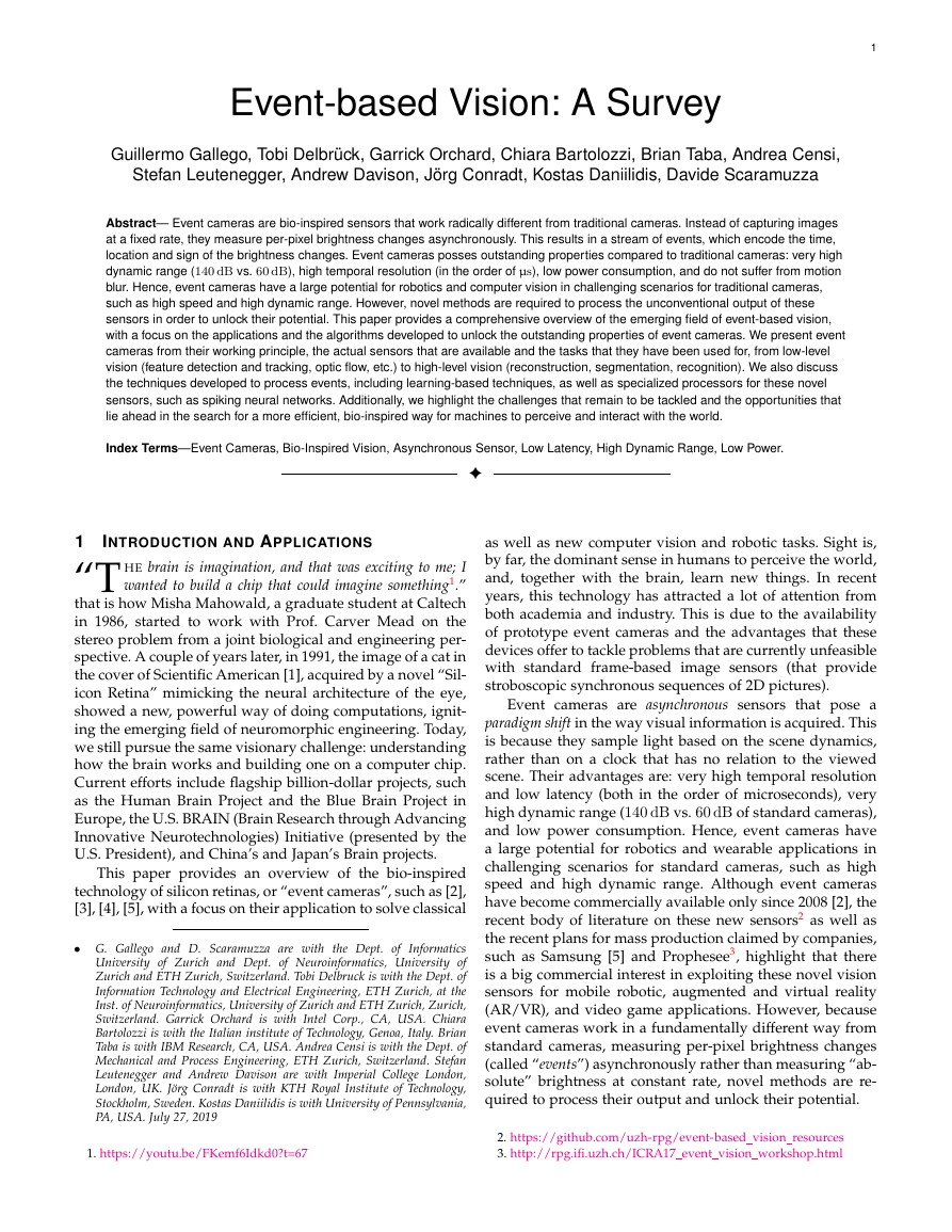
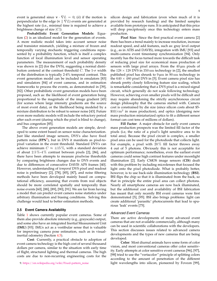
asynchronously and independently for every pixel (Fig. 1).
Thus, the output of an event camera is a variable data-
rate sequence of digital “events” or “spikes”, with each
event representing a change of brightness (log intensity)4 of
predefined magnitude at a pixel at a particular time5 (Fig. 1,
top right) (Section 2.4). This encoding is inspired by the
spiking nature of biological visual pathways (Section 3.3).
Each pixel memorizes the log intensity each time it sends an
event, and continuously monitors for a change of sufficient
4. Brightness is a perceived quantity; for brevity we use it to refer to
log intensity since they correspond closely for uniformly-lighted scenes.
5. Nomenclature: “Event cameras” output data-driven events that
signal a place and time. This nomenclature has evolved over the past
decade: originally they were known as address-event representation
(AER) silicon retinas, and later they became event-based cameras. In
general, events can signal any kind of information (intensity, local
spatial contrast, etc.), but over the last five years or so, the term “event
camera” has unfortunately become practically synonymous with the
particular representation of brightness change output by DVS’s.
2
Figure 1. Summary of the DAVIS camera [4], [57], comprising an event-
based dynamic vision sensor (DVS [56]) and a frame-based active pixel
sensor (APS) in the same pixel array, sharing the same photodiode in
each pixel. Top left: simplified circuit diagram of the DAVIS pixel. Top
right: schematic of the operation of a DVS pixel, converting light into
events. Center: pictures of the DAVIS chip and USB camera. Bottom
left: space-time view, on the image plane, of frames and events caused
by a spinning dot. Bottom right: frame and overlaid events of a natural
scene; the frames lag behind the low-latency events. Images adapted
from [4], [58].
magnitude from this memorized value (Fig. 1, top left).
When the change exceeds a threshold, the camera sends
an event, which is transmitted from the chip with the x, y
location, the time t, and the 1-bit polarity p of the change
(i.e., brightness increase (“ON”) or decrease (“OFF”)). This
event output is illustrated in Fig. 1, bottom.
The events are transmitted from the pixel array to pe-
riphery and then out of the camera using a shared digital
output bus, typically by using some variety of address-
event representation (AER) readout [59], [60]. This AER bus
can become saturated, which perturbs the times that events
are sent. Event cameras achieve readout rates ranging from
2 MHz [2] to 300 MHz [5], depending on the chip and type
of hardware interface.
Hence, event cameras are data-driven sensors: their
output depends on the amount of motion or brightness
change in the scene. The faster the motion, the more events
per second are generated, since each pixel adapts its delta
modulator sampling rate to the rate of change of the log
intensity signal that it monitors. Events are timestamped
with microsecond resolution and are transmitted with sub-
millisecond latency, which make these sensors react quickly
to visual stimuli.
The incident light at a pixel is a product of scene illumi-
nation and surface reflectance. Thus, a log intensity change
in the scene generally signals a reflectance change (because
usually the illumination is constant and the log of a product
is the sum of the logs). Thus, these reflectance changes are
mainly a result from movement of objects in the field of
�
3
DVS event camera had its genesis in a frame-based silicon
retina design where the continuous-time photoreceptor was
capacitively coupled to a readout circuit that was reset
each time the pixel was sampled [62]. More recent event
camera technology has been reviewed in the electronics and
neuroscience literature [6], [60], [63], [64], [65], [66].
Although surprisingly many applications can be solved
by only processing events (i.e., brightness changes), it be-
came clear that some also require some form of static output
(i.e., “absolute” brightness). To address this shortcoming,
there have been several developments of cameras that con-
currently output dynamic and static information.
The Asynchronous Time Based Image Sensor (ATIS) [3],
[67] has pixels that contain a DVS subpixel that triggers
another subpixel to read out the absolute intensity. The
trigger resets a capacitor to a high voltage. The charge is
bled away from this capacitor by another photodiode. The
brighter the light, the faster the capacitor discharges. The
ATIS intensity readout transmits two more events coding
the time between crossing two threshold voltages. This way,
only pixels that change provide their new intensity values.
The brighter the illumination, the shorter the time between
these two events. The ATIS achieves large static dynamic
range (>120 dB). However, the ATIS has the disadvantage
that pixels are at least double the area of DVS pixels. Also,
in dark scenes the time between the two intensity events can
be long and the readout of intensity can be interrupted by
new events ( [68] proposes a workaround to this problem).
The widely-used Dynamic and Active Pixel Vision Sen-
sor (DAVIS) illustrated in Fig. 1 combines a conventional
active pixel sensor (APS) [69] in the same pixel with DVS [4],
[57]. The advantage over ATIS is a much smaller pixel size
since the photodiode is shared and the readout circuit only
adds about 5 % to the DVS pixel area. Intensity (APS) frames
can be triggered on demand, by analysis of DVS events,
although this possibility is seldom exploited7. However, the
APS readout has limited dynamic range (55 dB) and like a
standard camera, it is redundant if the pixels do not change.
Commercial Cameras: These and other types or
varieties of DVS-based event cameras are developed com-
mercially by companies iniVation, Insightness, Samsung,
CelePixel, and Prophesee; some of these companies offer de-
velopment kits. Several developments are currently poised
to enter mass production, with the limiting factor being
pixel size; the most widely used event cameras have quite
large pixels: DVS128 (40 µm), ATIS (30 µm), DAVIS240 and
DAVIS346 (18.5 µm). The smallest published DVS pixel [5],
by Samsung, is 9 µm; while conventional global shutter
industrial APS are typically in the range of 2 µm–4 µm. Low
spatial resolution is certainly a limitation for application,
although many of the seminal publications are based on
the 128 × 128 pixel DVS128 [56]. The DVS with largest
published array size has only about VGA spatial resolution
(768 × 640 pixels [70]).
2.2 Advantages of Event cameras
Event cameras present numerous advantages over standard
cameras:
7. https://github.com/SensorsINI/jaer/blob/master/src/eu/
seebetter/ini/chips/davis/DavisAutoShooter.java
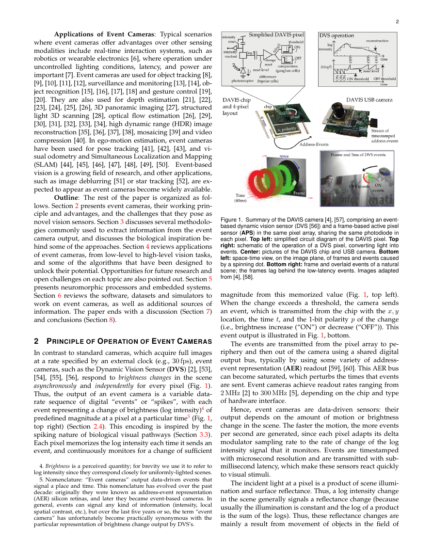
(a) Measurement setup
(b) Measured responses for two
DC levels of illumination.
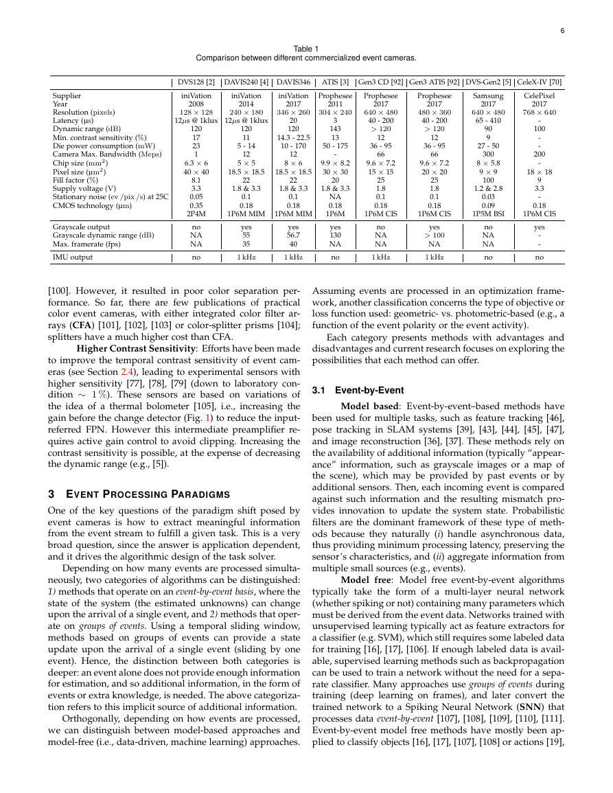
Figure 2. Shows the event transfer function from a single DVS pixel
in response to sinusoidal LED stimulation. The background (BG) events
cause additional ON events at very low frequencies. The 60 fps camera
curve shows the transfer function including aliasing from frequencies
above the Nyquist frequency. Adapted from [2].
view. That is why the DVS brightness change events have a
built-in invariance to scene illumination [2].
Comparing Bandwidths of DVS Pixels and Frame-
based Camera: Although DVS pixels are fast, like any phys-
ical transducer, they have a finite bandwidth: if the incom-
ing light intensity varies too quickly, the front end photore-
ceptor circuits filter out the variations. The rise and fall time
that is analogous to the exposure time in standard image
sensors is the reciprocal of this bandwidth. Fig. 2 shows an
example of measured DVS pixel frequency response. The
measurement setup (Fig. 2a) uses a sinusoidally-varying
generated signal to measure the response. Fig. 2b shows
that, at low frequencies, the DVS pixel produces a certain
number of events per cycle. Above some cutoff frequency,
the variations are filtered out by the photoreceptor dy-
namics and the number of events per cycle drops. This
cutoff frequency is a monotonically increasing function of
light intensity. At the brighter light intensity, the DVS pixel
bandwidth is about 3 kHz, equivalent to an exposure time of
about 300 µs. At 1000× lower intensity, the DVS bandwidth
is reduced to about 300 Hz. Even when the LED brightness is
reduced by a factor of 1000, the frequency response of DVS
pixels is ten times higher than the 30 Hz Nyquist frequency
from a 60 fps image sensor. Also, the frame-based camera
aliases frequencies above the Nyquist frequency back to
the baseband, whereas the DVS pixel does not due to the
continuous time response.
2.1 Event Camera Types
The first silicon retina was developed by Mahowald and
Mead at Caltech during the period 1986-1992, in Ph.D. thesis
work [61] that was awarded the prestigious Clauser prize6.
Mahowald and Mead’s sensor had logarithmic pixels, was
modeled after the three-layer Kufler retina, and produced
as output spike events using the AER protocol. However,
it suffered from several shortcomings: each wire-wrapped
retina board required precise adjustment of biasing poten-
tiometers; there was considerable mismatch between the
responses of different pixels; and pixels were too large to
be a device of practical use. Over the next decade the neu-
romorphic community developed a series of silicon retinas.
A summary of these developments is provided in [60]. The
6. http://www.gradoffice.caltech.edu/current/clauser
~300 nit2:1 contrasttimeVFunctiongeneratorLightfilterCameraLensf/1.2LED012345678DVS events / cyclestimulus frequency [Hz]1101001k10knoise60 fps frame camera1000X darkerBrightlighting.1�
High Temporal Resolution: monitoring of brightness
changes is fast, in analog circuitry, and the read-out of the
events is digital, with a 1 MHz clock, which means that
events are detected and timestamped with microsecond
resolution. Therefore, event cameras can capture very fast
motions, without suffering from motion blur typical of
frame-based cameras.
Low Latency: each pixel works independently and there
is no need to wait for a global exposure time of the frame:
as soon as the change is detected, it is transmitted. Hence,
event cameras have minimal latency: about 10 µs on the lab
bench, and sub-millisecond in the real world.
Low Power: Because event cameras transmit only bright-
ness changes, and thus remove redundant data, power is
only used to process changing pixels. At the die level, most
event cameras use on the order of 10 mW, and there are
prototypes that achieve less than 10 µW. Embedded event-
camera systems where the sensor is directly interfaced to a
processor have demonstrated system-level power consump-
tion (i.e., sensing plus processing) of 100 mW or less [19],
[71], [72], [73], [74].
High Dynamic Range (HDR). The very high dynamic
range of event cameras (>120 dB) notably exceeds the 60 dB
of high-quality, frame-based cameras, making them able to
acquire information from moonlight to daylight. It is due
to the facts that the photoreceptors of the pixels operate
in logarithmic scale and each pixel works independently,
not waiting for a global shutter. Like biological retinas, DVS
pixels can adapt to very dark as well as very bright stimuli.
2.3 Challenges Due To The Novel Sensing Paradigm
Event cameras represent a paradigm shift in acquisition of
visual information. Hence, they pose some challenges:
1) Novel Algorithms: The output of event cameras is
fundamentally different from that of standard cameras.
Thus, frame-based vision algorithms designed for image
sequences are not directly applicable. Specifically, events
depend not only on the scene brightness, but also on the
current and past motion between the scene and the camera.
Novel algorithms are thus required to process the event
camera output to unlock the advantages of the sensor.
2) Information Processing: Each event contains binary (in-
crease/decrease) brightness change information, as opposed
to the grayscale information that standard cameras provide.
Thus, it poses the question: what is the best way to extract
information from the events relevant for a given task?
3) Noise and Dynamic Effects: All vision sensors are noisy
because of the inherent shot noise in photons and from
transistor circuit noise, and they also have non-idealities.
This situation is especially true for event cameras, where the
process of quantization of brightness change information is
complex and has not been completely characterized. Hence,
how can noise and non-ideal effects be modeled to better
extract meaningful information from the events?
2.4 Event Generation Model
An event camera [2] has independent pixels that respond
.
= log(I) (“bright-
to changes in their log photocurrent L
.
ness”). Specifically, in a noise-free scenario, an event ek
=
= (xk, yk) and at
.
(xk, tk, pk) is triggered at pixel xk
4
time tk as soon as the brightness increment since the last
event at the pixel, i.e.
= L(xk, tk) − L(xk, tk − ∆tk),
.
(1)
reaches a temporal contrast threshold ±C (with C > 0)
(Fig. 1 top right), i.e.,
∆L(xk, tk)
∆L(xk, tk) = pk C,
(2)
where ∆tk is the time elapsed since the last event at the
same pixel, and the polarity pk ∈ {+1,−1} is the sign of the
brightness change [2].
The contrast sensitivity C is determined by the pixel
bias currents [75], [76], which set the speed and threshold
voltages of the change detector in Fig. 1 and are generated
by an on-chip digitally-programmed bias generator. The
sensitivity C can be estimated knowing these currents [75].
In practice, positive (“ON”) and negative (“OFF”) events
may be triggered according to different thresholds, C +, C−.
Typical DVS’s can set thresholds between 15 %–50 % illumi-
nation change. The lower limit on C is determined by noise
and pixel to pixel mismatch (variability) of C; setting C too
low results in a storm of noise events, starting from pixels
with low values of C. Experimental DVS’s with higher
photoreceptor gain are capable of lower thresholds, e.g.,
1 % [77], [78], [79]; however these values are only obtained
under very bright illumination and ideal conditions. Funda-
mentally, the pixel must react to a small change in the pho-
tocurrent in spite of the shot noise present in this current.
This shot noise limitation sets the relation between threshold
and speed of the DVS under a particular illumination and
desired detection reliability condition [79], [80].
Events and the Temporal Derivative of Brightness:
Eq. (2) states that event camera pixels set a threshold on
magnitude of the brightness change since the last event
happened. For a small ∆tk, such an increment (2) can be
approximated using Taylor’s expansion by ∆L(xk, tk) ≈
∂L
∂t (xk, tk)∆tk, which allows us to interpret the events as
providing information about the temporal derivative of
brightness:
∂L
∂t
(xk, tk) ≈ pk C
∆tk
.
(3)
This is an indirect way of measuring brightness, since with
standard cameras we are used to measuring absolute bright-
ness. This interpretation may be taken into account to design
principled event-based algorithms, such as [37], [81].
Events are Caused by Moving Edges: Assuming
constant illumination, linearizing (2) and using the constant
brightness assumption one can show that events are caused
by moving edges. For small ∆t, the intensity increment (2)
can be approximated by8:
∆L ≈ −∇L · v∆t,
(4)
that is, it is caused by an brightness gradient ∇L(xk, tk) =
(∂xL, ∂yL) moving with velocity v(xk, tk) on the image
.
= v∆t. As the dot prod-
plane, over a displacement ∆x
uct (4) conveys: (i) if the motion is parallel to the edge, no
8. Eq. (4) can be shown [82] by substituting the brightness constancy
assumption (i.e., optical flow constraint) ∂L
∂t (x(t), t) + ∇L(x(t), t) ·
˙x(t) = 0, with image-point velocity v ≡ ˙x, in Taylor’s approximation
∆L(x, t)
.
= L(x, t) − L(x, t − ∆t) ≈ ∂L
∂t (x, t)∆t.
�
event is generated since v · ∇L = 0; (ii) if the motion is
perpendicular to the edge (v ∇L) events are generated at
the highest rate (i.e., minimal time is required to achieve a
brightness change of size |C|).
Probabilistic Event Generation Models: Equa-
tion (2) is an idealized model for the generation of events.
A more realistic model takes into account sensor noise
and transistor mismatch, yielding a mixture of frozen and
temporally varying stochastic triggering conditions repre-
sented by a probability function, which is itself a complex
function of local illumination level and sensor operating
parameters. The measurement of such probability density
was shown in [2] (for the DVS), suggesting a normal distri-
bution centered at the contrast threshold C. The 1-σ width
of the distribution is typically 2-4% temporal contrast. This
event generation model can be included in emulators [83]
and simulators [84] of event cameras, and in estimation
frameworks to process the events, as demonstrated in [39],
[82]. Other probabilistic event generation models have been
proposed, such as: the likelihood of event generation being
proportional to the magnitude of the image gradient [45]
(for scenes where large intensity gradients are the source
of most event data), or the likelihood being modeled by a
mixture distribution to be robust to sensor noise [43]. Future
even more realistic models will include the refractory period
after each event (during which the pixel is blind to change),
and bus congestion [85].
The above event generation models are simple, devel-
oped to some extent based on sensor noise characterization.
Just like standard image sensors, DVS’s also have fixed
pattern noise (FPN9), but in DVS it manifests as pixel-to-
pixel variation in the event threshold. Standard DVS’s can
achieve minimum C ≈ ±15 %, with a standard deviation
of about 2.5 %–4 % contrast between pixels [2], [86], and
there have been attempts to measure pixelwise thresholds
by comparing brightness changes due to DVS events and
due to differences of consecutive DAVIS APS frames [40].
However, understanding of temporal DVS pixel and readout
noise is preliminary [2], [78], [85], [87], and noise filtering
methods have been developed mainly based on compu-
tational efficiency, assuming that events from real objects
should be more correlated spatially and temporally than
noise events [60], [88], [89], [90], [91]. We are far from having
a model that can predict event camera noise statistics under
arbitrary illumination and biasing conditions. Solving this
challenge would lead to better estimation methods.
2.5 Event Camera Availability
Table 1 shows currently popular event cameras. Some of
them also provide absolute intensity (e.g., grayscale) output,
and some also have an integrated Inertial Measurement Unit
(IMU) [93]. IMUs act as a vestibular sense that is valuable
for improving camera pose estimation, such as in visual-
inertial odometry (Section 4.5).
Cost: Currently, a practical obstacle to adoption of
event camera technology is the high cost of several thousand
dollars per camera, similar to the situation with early time
of flight, structured lighting and thermal cameras. The high
costs are due to non-recurring engineering costs for the
9. https://en.wikipedia.org/wiki/Fixed-pattern noise
5
silicon design and fabrication (even when much of it is
provided by research funding) and the limited samples
available from prototype runs. It is anticipated that this price
will drop precipitously once this technology enters mass
production.
Pixel Size: Since the first practical event camera [2]
there has been a trend mainly to increase resolution, increase
readout speed, and add features, such as: gray level output
(e.g., as in ATIS and DAVIS), integration with IMU [93] and
multi-camera event timestamp synchronization [94]. Only
recently has the focus turned more towards the difficult task
of reducing pixel size for economical mass production of
sensors with large pixel arrays. From the 40 µm pixels of
the 128 × 128 DVS in 350 nm technology in [2], the smallest
published pixel has shrunk to 9 µm in 90 nm technology in
the 640 × 480 pixel DVS in [5]. Event camera pixel size has
shrunk pretty closely following feature size scaling, which
is remarkable considering that a DVS pixel is a mixed-signal
circuit, which generally do not scale following technology.
However, achieving even smaller pixels will be difficult and
may require abandoning the strictly asynchronous circuit
design philosophy that the cameras started with. Camera
cost is constrained by die size (since silicon costs about $5-
$10/cm2 in mass production), and optics (designing new
mass production miniaturized optics to fit a different sensor
format can cost tens of millions of dollars).
Fill Factor: A major obstacle for early event camera
mass production prospects was the limited fill factor of the
pixels (i.e, the ratio of a pixel’s light sensitive area to its
total area). Because the pixel circuit is complex, a smaller
pixel area can be used for the photodiode that collects light.
For example, a pixel with 20 % fill factor throws away
4 out of 5 photons. Obviously this is not acceptable for
optimum performance; nonetheless, even the earliest event
cameras could sense high contrast features under moonlight
illumination [2]. Early CMOS image sensors (CIS) dealt
with this problem by including microlenses that focused the
light onto the pixel photodiode. What is probably better,
however, is to use back-side illumination technology (BSI).
BSI flips the chip so that it is illuminated from the back, so
that in principle the entire pixel area can collect photons.
Nearly all smartphone cameras are now back illuminated,
but the additional cost and availability of BSI fabrication
has meant that only recently BSI event cameras were first
demonstrated [5], [95]. BSI also brings problems: light can
create additional ‘parasitic’ photocurrents that lead to spu-
rious ‘leak’ events [75].
Advanced Event Cameras
There are active developments of more advanced event
cameras that are not available commercially, although many
can be used in scientific collaborations with the developers.
This section discusses issues related to advanced camera
developments and the types of new cameras that are being
developed.
Color: Most diurnal animals have some form of color
vision, and most conventional cameras offer color sensitiv-
ity. Early attempts at color sensitive event cameras [96], [97],
[98] tried to use the “vertacolor” principle of splitting colors
according to the amount of penetration of the different
light wavelengths into silicon, pioneered by Foveon [99],
�
Comparison between different commercialized event cameras.
Table 1
6
DVS128 [2] DAVIS240 [4] DAVIS346 ATIS [3] Gen3 CD [92] Gen3 ATIS [92] DVS-Gen2 [5] CeleX-IV [70]
iniVation
Prophesee
Prophesee
Prophesee
CelePixel
Samsung
iniVation
iniVation
2017
640 × 480
40 - 200
> 120
36 - 95
12
66
9.6 × 7.2
15 × 15
25
1.8
0.1
0.18
2017
480 × 360
40 - 200
> 120
36 - 95
12
66
9.6 × 7.2
20 × 20
25
1.8
0.1
0.18
2017
640 × 480
65 - 410
90
9
27 - 50
300
8 × 5.8
9 × 9
100
1.2 & 2.8
0.03
0.09
2017
768 × 640
-
100
-
-
200
-
9
3.3
-
0.18
18 × 18
1P6M CIS
1P6M CIS
1P5M BSI
1P6M CIS
no
NA
NA
1 kHz
yes
> 100
NA
1 kHz
no
NA
NA
no
yes
-
-
no
240 × 180
128 × 128
12µs @ 1klux 12µs @ 1klux
346 × 260
304 × 240
Supplier
Year
Resolution (pixels)
Latency (µs)
Dynamic range (dB)
Min. contrast sensitivity (%)
Die power consumption (mW)
Camera Max. Bandwidth (Meps)
Chip size (mm2)
Pixel size (µm2)
Fill factor (%)
Supply voltage (V)
Stationary noise (ev /pix /s) at 25C
CMOS technology (µm)
2008
120
17
23
1
6.3 × 6
40 × 40
8.1
3.3
0.05
0.35
2P4M
Grayscale output
Grayscale dynamic range (dB)
Max. framerate (fps)
IMU output
no
NA
NA
no
2014
120
11
5 - 14
12
5 × 5
22
18.5 × 18.5
1.8 & 3.3
2017
20
120
14.3 - 22.5
10 - 170
12
8 × 6
22
18.5 × 18.5
1.8 & 3.3
2011
3
143
13
-
50 - 175
9.9 × 8.2
30 × 30
1.8 & 3.3
20
0.1
0.18
0.1
0.18
NA
0.18
1P6M MIM 1P6M MIM 1P6M
yes
130
NA
no
yes
56.7
40
yes
55
35
1 kHz
1 kHz
[100]. However, it resulted in poor color separation per-
formance. So far, there are few publications of practical
color event cameras, with either integrated color filter ar-
rays (CFA) [101], [102], [103] or color-splitter prisms [104];
splitters have a much higher cost than CFA.
Higher Contrast Sensitivity: Efforts have been made
to improve the temporal contrast sensitivity of event cam-
eras (see Section 2.4), leading to experimental sensors with
higher sensitivity [77], [78], [79] (down to laboratory con-
dition ∼ 1 %). These sensors are based on variations of
the idea of a thermal bolometer [105], i.e., increasing the
gain before the change detector (Fig. 1) to reduce the input-
referred FPN. However this intermediate preamplifier re-
quires active gain control to avoid clipping. Increasing the
contrast sensitivity is possible, at the expense of decreasing
the dynamic range (e.g., [5]).
3 EVENT PROCESSING PARADIGMS
One of the key questions of the paradigm shift posed by
event cameras is how to extract meaningful information
from the event stream to fulfill a given task. This is a very
broad question, since the answer is application dependent,
and it drives the algorithmic design of the task solver.
Depending on how many events are processed simulta-
neously, two categories of algorithms can be distinguished:
1) methods that operate on an event-by-event basis, where the
state of the system (the estimated unknowns) can change
upon the arrival of a single event, and 2) methods that oper-
ate on groups of events. Using a temporal sliding window,
methods based on groups of events can provide a state
update upon the arrival of a single event (sliding by one
event). Hence, the distinction between both categories is
deeper: an event alone does not provide enough information
for estimation, and so additional information, in the form of
events or extra knowledge, is needed. The above categoriza-
tion refers to this implicit source of additional information.
Orthogonally, depending on how events are processed,
we can distinguish between model-based approaches and
model-free (i.e., data-driven, machine learning) approaches.
Assuming events are processed in an optimization frame-
work, another classification concerns the type of objective or
loss function used: geometric- vs. photometric-based (e.g., a
function of the event polarity or the event activity).
Each category presents methods with advantages and
disadvantages and current research focuses on exploring the
possibilities that each method can offer.
3.1 Event-by-Event
Model based: Event-by-event–based methods have
been used for multiple tasks, such as feature tracking [46],
pose tracking in SLAM systems [39], [43], [44], [45], [47],
and image reconstruction [36], [37]. These methods rely on
the availability of additional information (typically “appear-
ance” information, such as grayscale images or a map of
the scene), which may be provided by past events or by
additional sensors. Then, each incoming event is compared
against such information and the resulting mismatch pro-
vides innovation to update the system state. Probabilistic
filters are the dominant framework of these type of meth-
ods because they naturally (i) handle asynchronous data,
thus providing minimum processing latency, preserving the
sensor’s characteristics, and (ii) aggregate information from
multiple small sources (e.g., events).
Model free: Model free event-by-event algorithms
typically take the form of a multi-layer neural network
(whether spiking or not) containing many parameters which
must be derived from the event data. Networks trained with
unsupervised learning typically act as feature extractors for
a classifier (e.g. SVM), which still requires some labeled data
for training [16], [17], [106]. If enough labeled data is avail-
able, supervised learning methods such as backpropagation
can be used to train a network without the need for a sepa-
rate classifier. Many approaches use groups of events during
training (deep learning on frames), and later convert the
trained network to a Spiking Neural Network (SNN) that
processes data event-by-event [107], [108], [109], [110], [111].
Event-by-event model free methods have mostly been ap-
plied to classify objects [16], [17], [107], [108] or actions [19],
�
[20], [112], and have targeted embedded applications [107],
often using custom SNN hardware [16], [19].
3.2 Groups of Events
7
Model based: Methods that operate on groups of
events aggregate the information contained in the events
to estimate the problem unknowns, usually without relying
on additional data. Since each event carries little information
and is subject to noise, several events must be processed to-
gether to yield a sufficient signal-to-noise ratio for the prob-
lem considered. This category can be further subdivided
into two: (i) methods that quantize temporal information of the
events and accumulate them into frames, possibly guided
by application or computing power, to re-utilize traditional,
image-based computer vision algorithms [113], [114], [115],
and (ii) methods that exploit the fine temporal information of
individual events for estimation, and therefore tend to de-
part from traditional computer vision algorithms [23], [26],
[32], [49], [116], [117], [118], [119], [120], [121]. The review [7]
quantitatively compares accuracy and computational cost
for frame-based versus event-driven optical flow.
Events are processed differently depending on their
representation. Some approaches use techniques for point
sets [30], [46], [117], [122], reasoning in terms of geometric
processing of the space-time coordinates of the events. Other
methods process events as tensors: time-surfaces (pixel-
map of last event timestamps) [88], [123], [124], event his-
tograms [32], etc. Others, [23], [26], combine both: warping
events as point sets to compute tensors for further analysis.
Model free (Deep Learning): So-called model free
methods operating on groups of events typically consist of
a deep neural network. Sample applications include clas-
sification [125], [126], steering angle prediction [127], [128],
and estimation of optical flow [33], [129], [130], depth [129]
or ego-motion [130]. These methods differentiate themselves
mainly in the representation of the input (events) and in the
loss functions that are optimized during training.
Since classical deep learning pipelines use tensors as
inputs, events have to be converted into such a dense, mul-
tichannel representation. Several representations have been
used, such as: pixelwise histograms of events [128], [131],
maps of most recent timestamps [33], [129], [132] (“time
surfaces” [17], [88]), or an interpolated voxel grid [38], [130],
which better preserves the spatio-temporal nature of the
events within a time interval. A general framework to con-
vert event streams into grid-based representations is given
in [133]. Alternatively, point set representations, which do
not require conversion, have been recently explored [134],
inspired by [135].
While loss functions in classification tasks use manually
annotated labels, networks for regression tasks from events
may be supervised by a third party ground truth (e.g., a
pose) [128], [131] or by an associated grayscale image [33] to
measure photoconsistency, or be completely unsupervised
(depending only on the training input events) [129], [130].
Loss functions for unsupervised learning from events are
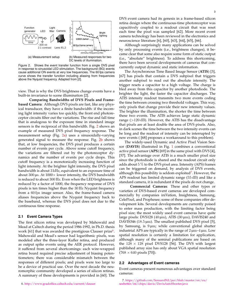
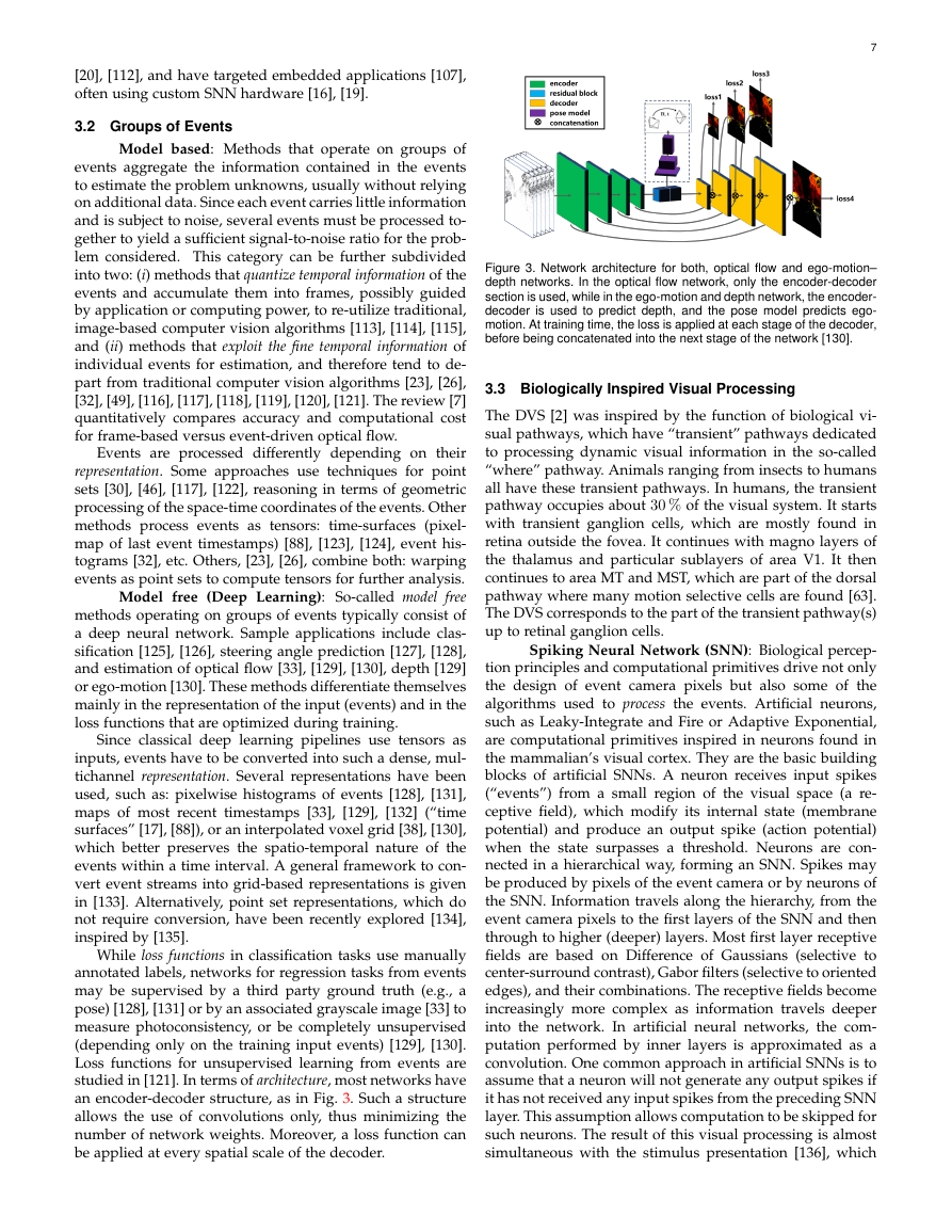
studied in [121]. In terms of architecture, most networks have
an encoder-decoder structure, as in Fig. 3. Such a structure
allows the use of convolutions only, thus minimizing the
number of network weights. Moreover, a loss function can
be applied at every spatial scale of the decoder.
Figure 3. Network architecture for both, optical flow and ego-motion–
depth networks. In the optical flow network, only the encoder-decoder
section is used, while in the ego-motion and depth network, the encoder-
decoder is used to predict depth, and the pose model predicts ego-
motion. At training time, the loss is applied at each stage of the decoder,
before being concatenated into the next stage of the network [130].
3.3 Biologically Inspired Visual Processing
The DVS [2] was inspired by the function of biological vi-
sual pathways, which have “transient” pathways dedicated
to processing dynamic visual information in the so-called
“where” pathway. Animals ranging from insects to humans
all have these transient pathways. In humans, the transient
pathway occupies about 30 % of the visual system. It starts
with transient ganglion cells, which are mostly found in
retina outside the fovea. It continues with magno layers of
the thalamus and particular sublayers of area V1. It then
continues to area MT and MST, which are part of the dorsal
pathway where many motion selective cells are found [63].
The DVS corresponds to the part of the transient pathway(s)
up to retinal ganglion cells.
Spiking Neural Network (SNN): Biological percep-
tion principles and computational primitives drive not only
the design of event camera pixels but also some of the
algorithms used to process the events. Artificial neurons,
such as Leaky-Integrate and Fire or Adaptive Exponential,
are computational primitives inspired in neurons found in
the mammalian’s visual cortex. They are the basic building
blocks of artificial SNNs. A neuron receives input spikes
(“events”) from a small region of the visual space (a re-
ceptive field), which modify its internal state (membrane
potential) and produce an output spike (action potential)
when the state surpasses a threshold. Neurons are con-
nected in a hierarchical way, forming an SNN. Spikes may
be produced by pixels of the event camera or by neurons of
the SNN. Information travels along the hierarchy, from the
event camera pixels to the first layers of the SNN and then
through to higher (deeper) layers. Most first layer receptive
fields are based on Difference of Gaussians (selective to
center-surround contrast), Gabor filters (selective to oriented
edges), and their combinations. The receptive fields become
increasingly more complex as information travels deeper
into the network. In artificial neural networks, the com-
putation performed by inner layers is approximated as a
convolution. One common approach in artificial SNNs is to
assume that a neuron will not generate any output spikes if
it has not received any input spikes from the preceding SNN
layer. This assumption allows computation to be skipped for
such neurons. The result of this visual processing is almost
simultaneous with the stimulus presentation [136], which
�
is very different from traditional convolutional networks,
where convolution is computed simultaneously at all loca-
tions at fixed time intervals.
Tasks: Bio-inspired models have been adopted for
several low-level visual tasks. For example, event-based
optical flow can be estimated by using spatio-temporally
oriented filters [88], [137], [138] that mimic the working prin-
ciple of receptive fields in the primary visual cortex [139],
[140]. The same type of oriented filters have been used to
implement a spike-based model of selective attention [141]
based on the biological proposal from [142]. Bio-inspired
models from binocular vision, such as recurrent lateral con-
nectivity and excitatory-inhibitory neural connections [143],
have been used to solve the event-based stereo correspon-
dence problem [61], [144], [145], [146], [147] or to control
binocular vergence on humanoid robots [148]. The visual
cortex has also inspired the hierarchical feature extraction
model proposed in [149], which has been implemented in
SNNs and used for object recognition. The performance of
such networks improves the better they extract information
from the precise timing of the spikes [150]. Early networks
were hand-crafted (e.g., using Gabor filters) [71], but recent
efforts let the network build receptive fields through brain-
inspired learning, such as Spike-Timing Dependent Plastic-
ity, yielding better recognition networks [106]. This research
is complemented by approaches where more computation-
ally inspired types of supervised learning, such as back-
propagation, are used in deep networks to efficiently im-
plement spiking deep convolutional networks [151], [152],
[153], [154], [155].
The advantages of the above methods over their tradi-
tional vision counterparts are lower latency and higher com-
putational efficiency. To build small, efficient and reactive
computational systems, insect vision is also a source of inspi-
ration for event-based processing. To this end, systems for
fast and efficient obstacle avoidance and target acquisition
in small robots have been developed [156], [157], [158] based
on models of neurons driven by DVS output that respond
to looming objects and trigger escape reflexes.
4 ALGORITHMS / APPLICATIONS
In this section, we review several works on event-based vi-
sion, grouped according to the task addressed. We start with
low-level vision on the image plane, such as feature detec-
tion, tracking, and optical flow estimation. Then, we discuss
tasks that pertain to the 3D structure of the scene, such
as depth estimation, structure from motion (SFM), visual
odometry (VO), sensor fusion (visual-inertial odometry)
and related subjects, such as intensity image reconstruction.
Finally, we consider segmentation, recognition and coupling
perception with control.
4.1 Feature Detection and Tracking
Feature detection and tracking on the image plane are
fundamental building blocks of many vision tasks such as
visual odometry, object segmentation and scene understand-
ing. Event cameras enable tracking asynchronously, adapted
to the dynamics of the scene and with low latency, high
dynamic range and low power. Thus, they allow to track in
the “blind” time between the frames of a standard camera.
8
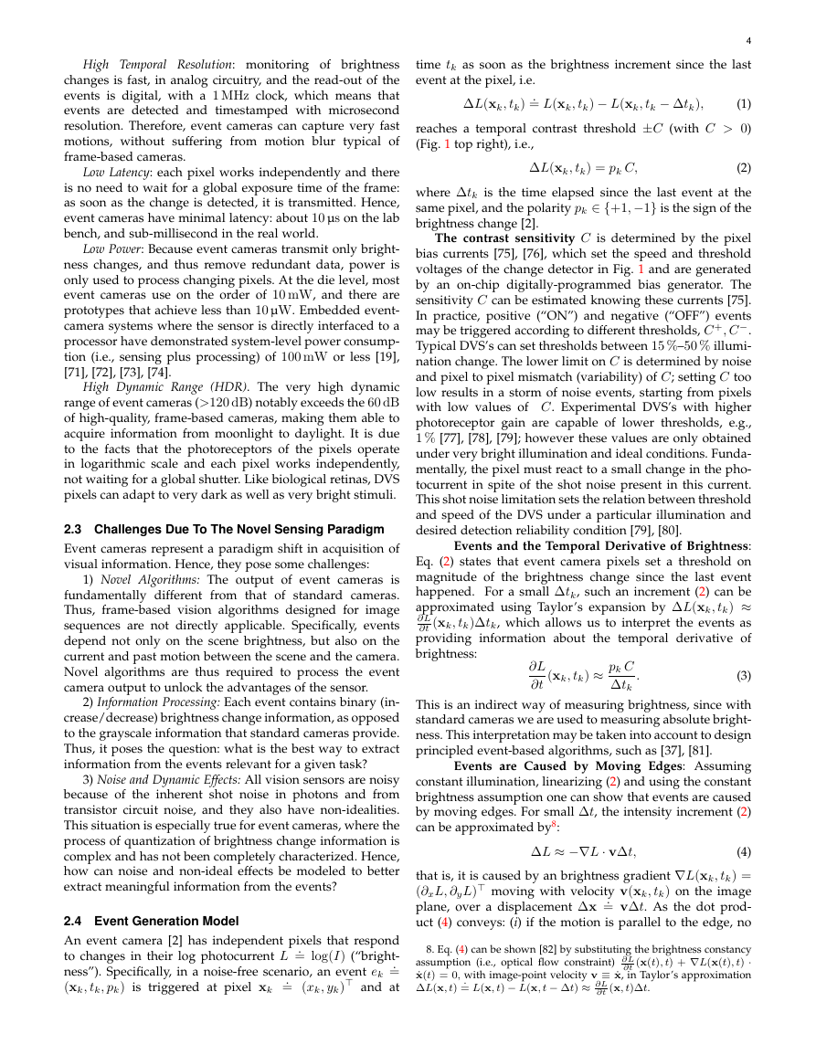
(a)
(b)
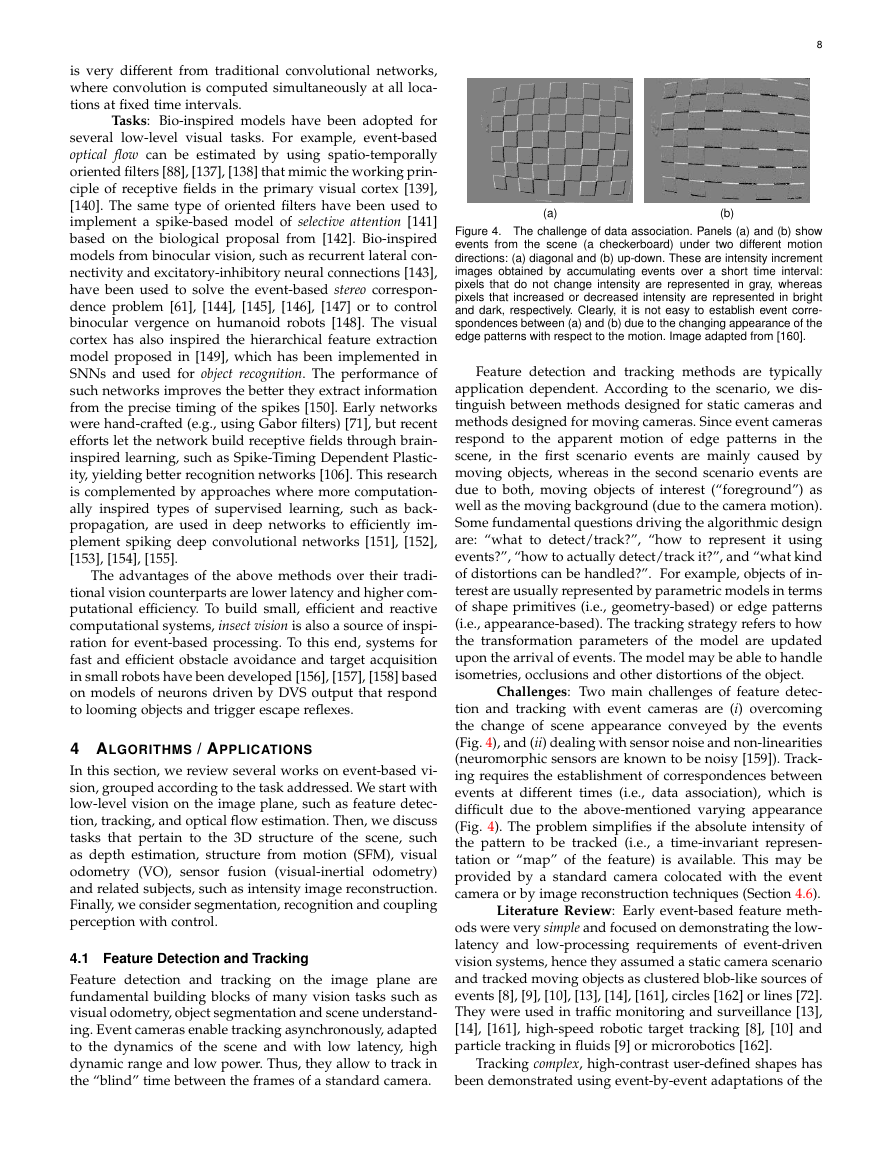
Figure 4. The challenge of data association. Panels (a) and (b) show
events from the scene (a checkerboard) under two different motion
directions: (a) diagonal and (b) up-down. These are intensity increment
images obtained by accumulating events over a short time interval:
pixels that do not change intensity are represented in gray, whereas
pixels that increased or decreased intensity are represented in bright
and dark, respectively. Clearly, it is not easy to establish event corre-
spondences between (a) and (b) due to the changing appearance of the
edge patterns with respect to the motion. Image adapted from [160].
Feature detection and tracking methods are typically
application dependent. According to the scenario, we dis-
tinguish between methods designed for static cameras and
methods designed for moving cameras. Since event cameras
respond to the apparent motion of edge patterns in the
scene, in the first scenario events are mainly caused by
moving objects, whereas in the second scenario events are
due to both, moving objects of interest (“foreground”) as
well as the moving background (due to the camera motion).
Some fundamental questions driving the algorithmic design
are: “what to detect/track?”, “how to represent it using
events?”, “how to actually detect/track it?”, and “what kind
of distortions can be handled?”. For example, objects of in-
terest are usually represented by parametric models in terms
of shape primitives (i.e., geometry-based) or edge patterns
(i.e., appearance-based). The tracking strategy refers to how
the transformation parameters of the model are updated
upon the arrival of events. The model may be able to handle
isometries, occlusions and other distortions of the object.
Challenges: Two main challenges of feature detec-
tion and tracking with event cameras are (i) overcoming
the change of scene appearance conveyed by the events
(Fig. 4), and (ii) dealing with sensor noise and non-linearities
(neuromorphic sensors are known to be noisy [159]). Track-
ing requires the establishment of correspondences between
events at different times (i.e., data association), which is
difficult due to the above-mentioned varying appearance
(Fig. 4). The problem simplifies if the absolute intensity of
the pattern to be tracked (i.e., a time-invariant represen-
tation or “map” of the feature) is available. This may be
provided by a standard camera colocated with the event
camera or by image reconstruction techniques (Section 4.6).
Literature Review: Early event-based feature meth-
ods were very simple and focused on demonstrating the low-
latency and low-processing requirements of event-driven
vision systems, hence they assumed a static camera scenario
and tracked moving objects as clustered blob-like sources of
events [8], [9], [10], [13], [14], [161], circles [162] or lines [72].
They were used in traffic monitoring and surveillance [13],
[14], [161], high-speed robotic target tracking [8], [10] and
particle tracking in fluids [9] or microrobotics [162].
Tracking complex, high-contrast user-defined shapes has
been demonstrated using event-by-event adaptations of the
�


 2023年江西萍乡中考道德与法治真题及答案.doc
 2012年重庆南川中考生物真题及答案.doc
 2013年江西师范大学地理学综合及文艺理论基础考研真题.doc
 2020年四川甘孜小升初语文真题及答案I卷.doc
 2020年注册岩土工程师专业基础考试真题及答案.doc
 2023-2024学年福建省厦门市九年级上学期数学月考试题及答案.doc
 2021-2022学年辽宁省沈阳市大东区九年级上学期语文期末试题及答案.doc
 2022-2023学年北京东城区初三第一学期物理期末试卷及答案.doc
 2018上半年江西教师资格初中地理学科知识与教学能力真题及答案.doc
 2012年河北国家公务员申论考试真题及答案-省级.doc
 2020-2021学年江苏省扬州市江都区邵樊片九年级上学期数学第一次质量检测试题及答案.doc
 2022下半年黑龙江教师资格证中学综合素质真题及答案.doc