For our other free eBooks,
Go to: 1 - 100 Transistor Circuits
Go to: 101 - 200 Transistor Circuits
Go to: 100 IC Circuits
For more data on the 555, see these pages:
555-Page 1 for CD users: 555-Page 1
555-Page 2 555-Page 2
555-Page 3 555-Page 3
555-Test 555-Test
For a list of every electronic symbol, see: Circuit Symbols.
For more articles and projects to suit the hobbyist: see TALKING ELECTRONICS WEBSITE
Save 50 - 555 Circuits (actually 76 Circuits) as: zip (800kB) or .doc
(1.2MB) or .pdf (900kB)
54 CIRCUITS as of 29-11-2009 Rev1.2 29-11-2009 - added Hysteresis (Schmitt
Trigger, Knight Rider-2, Morse Code,
Music Box, Reaction Timer Game
61 CIRCUITS as of 5-12-2009 Rev1.3 5-12-2009 - added Traffic Lights, Driving White
LEDs, TV Remote Control Jammer,
3x3x3 Cube, Up/Down Fading LED, H-Bridge, H-Bridge with PWM.
64 CIRCUITS as of 14-12-2009 Bike Turning Signal, 555 on 24v, Police Lights, LED Dice,
Roulette, Model Railway Time
71 CIRCUITS as of 1-1-2010 plus: Servo Controller, Curtain Closer, Stepper Motor
Controller, 4-way Traffic Lights,
TE555-1 Chip: Stepper Motor Controller,
76 CIRCUITS as of 10-1-2010 plus:
�
See TALKING ELECTRONICS WEBSITE
email Colin Mitchell: talking@tpg.com.au
INTRODUCTION
This e-book covers the 555.
The 555 is everywhere and it is one of the cheapest and most-rugged
chips on the market.
It comes as a TTL 555 and will operate from 4v to about 16-18v. It
costs from 20 cents (eBay) to $1.20 depending on the quantity and
distributor. The circuitry inside the chip takes about 10mA - even
when the output is not driving a load. This means it is not suitable for
battery operation if the chip is to be powered ALL THE TIME.
The 555 is also available as a CMOS chip (ICM7555 or ICL7555 or TLC555)
and will operate from 2v to 18v and takes 60uA when the circuitry
inside the chip is powered. The "7555" costs from 60 cents (eBay) to
$2.00
We call the TTL version "555" and the CMOS version "7555." This is
called ELECTRONICS JARGON.
The 555 comes as a single timer in an 8-pin package or a dual timer
(556) in a 14 pin package.
The 7555 comes as a single timer in an 8-pin package or a dual timer
(7556) in a 14 pin package.
The 555 and 7555 are called TIMERS or Timer Chips. They contain about
28 transistors and the only extra components you need are called
TIMING COMPONENTS. This is an external resistor and capacitor. When a
capacitor is connected to a voltage, it takes a period of time to charge.
If a resistor is placed in series with the capacitor, the timing will
increase. The chip detects the rising and falling voltage on the
capacitor. When the voltage on the capacitor is 2/3 of the supply the
output goes LOW and when the voltage falls to 1/3, the output goes
HIGH.
We can also do other things with the chip such as "freezing" or halting
its operation, or allowing it to produce a single HIGH-LOW on the
output pin. This is called a "ONE-SHOT" or MONOSTABLE OPERATION.
When the chip produces an output frequency above 1 cycle per second,
(1Hz), the circuit is called an OSCILLATOR and below one cycle per
second, it is called a TIMER.
But the chip should not be called a "555 Timer," as it has so many
applications. That's why we call it a "555." (triple 5)
For photos of nearly every electronic component, see this website:
https://www.egr.msu.edu/eceshop/Parts_Inventory/totalinventory.php
You can also search the web for videos showing the 555 in action.
Here are a few:
Making A 555 LED Flasher – Video Tutorial
Three 555 LED Flasher
555 Timer Flasher
�
Fading LED with 555 timer
Each website has lots more videos and you can see exactly how the
circuits work. But there is nothing like building the circuit and that's
why you need to re-enforce your knowledge by ACTUAL
CONSTRUCTION.
Learning Electronics is like building a model with Lego bricks. Each
"topic" or "subject" or "area" must be covered fully and perfectly, just
like a Lego brick is perfect and fits with interference-fit to the next
block. When you complete this eBook, you can safely say you will have
mastered the 555 - one more "building block" under your belt and in the
process learn about DC motors, Stepper motors, servos, 4017 chips,
LEDs and lots of other things. Any one of these can take you off in a
completely different direction. So, lets start . . .
Colin Mitchell
TALKING ELECTRONICS.
talking@tpg.com.au
To save space we have not provided lengthy explanations of how any of
the circuits work. This has already been covered in TALKING
ELECTRONICS Basic Electronics Course, and can be obtained on a CD for
$10.00 (posted to anywhere in the world) See Talking Electronics
website (http://www.talkingelectronics.com) for more details on the
555 by clicking on the following four pages: 555-Page 1 555-Page 2
555-Page 3 555-Test
Many of the circuits have been designed by Colin Mitchell: Music Box,
Reaction Timer Game, Traffic Lights, TV Remote Control Jammer,
3x3x3 Cube, while others are freely available on the web. But this
eBook has brought everything together and covers just about every
novel 555 circuit. If you think you know everything about the 555, take
the 555-Test and you will be surprised!
SI NOTATION
All the schematics in this eBook have components that are labelled
using the System International (SI) notation system. The SI system is an
easy way to show values without the need for a decimal point.
Sometimes the decimal point is difficult to see and the SI system
overcomes this problem and offers a clear advantage.
Resistor values are in ohms (R), and the multipliers are: k for kilo, M for
Mega. Capacitance is measured in farads (F) and the sub-multiples are u
for micro, n for nano, and p for pico. Inductors are measured in Henrys
(H) and the sub-multiples are mH for milliHenry and uH for microHenry.
A 10 ohm resistor would be written as 10R and a 0.001u capacitor as 1n.
The markings on components are written slightly differently to the way
they are shown on a circuit diagram (such as 100p on a circuit and 101
on the capacitor) and you will have to look on the internet under Basic
Electronics to learn about these differences.
NEW! FROM TALKING
ELECTRONICS
A new range of 555 chips have been designed by Talking Electronics to
carry out tasks that normally need 2 or more chips.
These chips are designated: TE 555-1, TE555-2 and the first project to
use the TE 555-1 is STEPPER MOTOR CONTROLLER TE555-1.
�
It's a revolutionary concept. Instead of using an old 8-pin TTL 555 chip,
you can use a new TE555-1,2,3 8-pin chip and save board space as well
as components. These new chips require considerably less external
componentry and the possibilities are endless. Depending on the
circuit, they can have a number of timing and frequency outputs as well
as a "power-down" feature that consumes almost no current when the
circuit is not operating. See the first project in this series: STEPPER
MOTOR CONTROLLER TE555-1.
How are your powers of observation?
Can you find the LED:
SQUARE WAVE
OSCILLATOR KIT
A Square Wave Oscillator Kit is available from
Talking Electronics for under $10.00. See full
details of circuit below.
(This link will send an email to Colin Mitchell
and you will be advised of costs and how to
send money via Paypal or credit card.)
Or email Colin Mitchell: talking@tpg.com.au
555 KIT
A kit of components to make
many of the circuits described
in this eBook is available for $10.00 plus $7.00
post.
Or email Colin Mitchell: talking@tpg.com.au
The kit contains the following components:
(plus extra 30 resistors and 10 capacitors for
experimenting), plus:
2 - 220R
2 - 1k
2 - 4k7
2 - 10k
2 - 33k
2- 100k
2 - 1M
1 - 10k mini pot
1 - 100k mini pot
�
2 - 10n
2 - 100n
1 - 10u electrolytic
1- 100u electrolytic
2 - 1N4148 signal diodes
2 - BC547 transistors
1 - BC557 transistor
1 - 555 timer chip
1 - 8 pin IC socket
1 - red LED
1 - green LED
1 - orange LED
1 - mini 8R speaker
1 - mini piezo
1 - LDR (Light Dependent Resistor)
1 - 10mH inductor
1 - push button
1 - tactile push button
1 - Experimenter Board (will take 8, 14 and 16
pin chips)
CONTENTS
Active High Trigger
Active Low Trigger
Amplifier using 555
Automatic Curtain Closer
Astable Multivibrator
Bi-Coloured LED
Bike Turning Signal
Bi-Polar LED Driver
Building the Circuits
Car Tachometer
Clark Zapper
Clicks Uneven
Continuity Tester
Curtain Closer
Dark Detector
Dice
Driving A Bi-Coloured LED
Driving A Relay
Driving White LEDs
Fading LED
Fastest 555 Oscillator
Flashing Indicators
Flashing Railroad Lights
Flip Flop
Function of each 555 pin
H-Bridge
H-Bridge with PWM
Headlight Flasher - faulty circuit
Hee Haw Siren
High Frequency 555 Oscillator
How to use the 555
Hysteresis
Organ
Police Lights
Police Siren
Powering A Project
Pulse Extender
Pulser - 74c14
PWM Controller
Railroad Lights (flashing)
Railway Time
Rain Alarm
Reaction Timer Game
Replacing 556 with two 555's
Resistor Colour Codes
Roulette
Schmitt Trigger
Screamer Siren - Light Controlled
Servo Controller
Servo Tester
Simplest 555 Oscillator
Siren 100dB
Square Wave Oscillator
Stepper Motor Controller
Stun Gun
Substituting a 555 - Part 1
Substituting a 555 - Part 2
Switch Debounce
Tachometer
TE555-1 Stepper Motor Controller
Ticking Bomb
Tilt Switch
Touch Switch
Touch ON-OFF
�
Increasing Output Current
Increasing Output Push-Pull Current
Inverter 12v to 240v
Inside the 555
Kitt Scanner
Knight Rider
Laser Ray Sound
Latch
Latch - using transistors
LED Dice
LED Dimmer
Light Controlled Screamer Siren
Light Detector
Lights - Traffic Lights
Low Frequency 555 Oscillator
Machine Gun
Mark-Space Ratio
Memory Cell
Mercury Switch Detector - faulty circuit
Metal Detector
Missing Pulse Detector - faulty circuit
Model Railway Time
Monostable 555
Morse Keyer
Mosquito Repeller
Motor Controller (stepper Motor)
Motor PWM
Multivibrator - Astable
Music Box
Negative Voltage
Normally Closed Trigger
One-Shot 555
THE 555 PINS
Here is the identification for each pin:
Toy Organ
Traffic Lights
Traffic Lights - 4 way
Transistor Tester
Trigger Timer - 74c14
Turning Signal
TV Remote Control Jammer
Uneven Clicks
Up/Down Fading LED
Using the 555
VCO
Voltage Doubler
Wailing Siren
Zapper (Dr Clark)
Zener Diode Tester
2 Minute Timer - 74c14
3x3x3 Cube
4 way Traffic Lights
10 Minute Timer - 74c14
12v to 240v Inverter
100dB Siren
555's - a list of substitutes
555 Amplifier
555 Kit of Components
555 Pinout
555 Mistakes (No-No's)
555 on 24v
555 VCO
556 Dual Timer
When drawing a circuit diagram, always draw the 555 as a building block, as shown below with the pins
in the following locations. This will help you instantly recognise the function of each pin:
�
Pin 1 GROUND. Connects to the 0v rail.
Pin 2 TRIGGER. Detects 1/3 of rail voltage to make output HIGH. Pin 2 has control over pin 6. If pin 2
is LOW, and pin 6 LOW, output goes and stays HIGH. If pin 6 HIGH, and pin 2 goes LOW, output goes
LOW while pin 2 LOW. This pin has a very high impedance (about 10M) and will trigger with about 1uA.
Pin 3 OUTPUT. (Pins 3 and 7 are "in phase.") Goes HIGH (about 2v less than rail) and LOW (about
0.5v less than 0v) and will deliver up to 200mA.
Pin 4 RESET. Internally connected HIGH via 100k. Must be taken below 0.8v to reset the chip.
Pin 5 CONTROL. A voltage applied to this pin will vary the timing of the RC network (quite
considerably).
Pin 6 THRESHOLD. Detects 2/3 of rail voltage to make output LOW only if pin 2 is HIGH. This pin
has a very high impedance (about 10M) and will trigger with about 0.2uA.
Pin 7 DISCHARGE. Goes LOW when pin 6 detects 2/3 rail voltage but pin 2 must be HIGH. If pin 2 is
HIGH, pin 6 can be HIGH or LOW and pin 7 remains LOW. Goes OPEN (HIGH) and stays HIGH when
pin 2 detects 1/3 rail voltage (even as a LOW pulse) when pin 6 is LOW. (Pins 7 and 3 are "in phase.")
Pin 7 is equal to pin 3 but pin 7 does not go high - it goes OPEN. But it goes LOW and will sink about
200mA
Pin 8 SUPPLY. Connects to the positive rail.
THE SIMPLEST 555 OSCILLATOR
The simplest 555 oscillator takes output pin 3 to capacitor C1 via resistor R1.
When the circuit is turned on, C1 is uncharged and output pin 3 is HIGH. C1 charges via
R1 and when Pin 6 detects 2/3 rail voltage, output pin 3 goes LOW. R1 now discharges
capacitor C1 and when pin 2 detects 1/3 rail voltage, output pin 3 goes HIGH to repeat
the cycle:
�
CHANGING THE MARK-SPACE RATIO
The amount of time when the output is HIGH is called the MARK and the time when the
output is LOW is called the SPACE.
In the above diagram the mark is the same length as the space and this is called 1:1
This ratio can be altered by adding a diode and resistor as shown in the following
diagrams. In the first diagram, the 555 comes ON with pin 3 low and pin 3 immediately
detects this low and makes pin 3 HIGH. The 10n is quickly charged via the diode and 4k7
and this is why the MARK is "short." When the capacitor is 2/3Vcc, pin 6 detects a HIGH
and the output of the 555 goes LOW. The 10n is discharged via the 33k and this creates
the long-duration SPACE (LOW). The second diagram creates a long-duration HIGH:
THE FASTEST 555 OSCILLATOR
The highest frequency can be obtained by connecting the output
to pins 2 and 6. This arrangement takes about 5mA and
produces an output as shown:
View the output on a CRO. Our 555 "Test Chip" produced a
frequency of 300kHz at 5v and 12v. (CMOS versions will operate
at a higher frequency.) Note the very short LOW TIME.
�


 Meta大模型论文:The Llama 3 Herd of Models.pdf
 ACS0709(传感器资料).PDF
 495个C语言常见问题集.pdf
 CS型可燃性气体传感器(106型和1003型)(传感器资料).pdf
 一种基于PWM的电压输出DAC电路设计.pdf
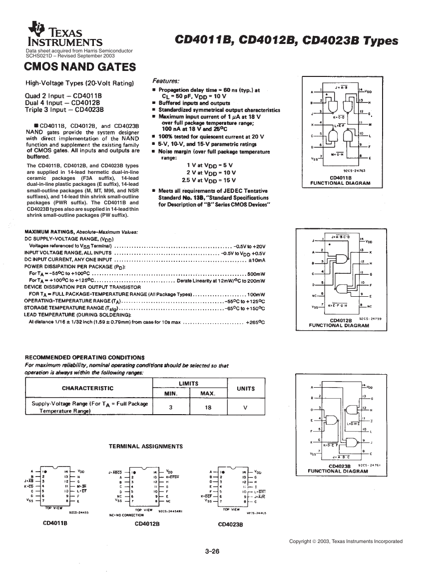 cd4011b(智能车电机驱动).pdf
 电路设计规范_中兴.pdf
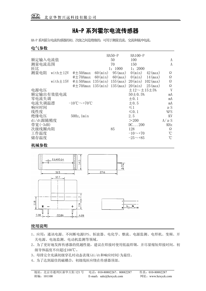 HA50-P(传感器资料).pdf
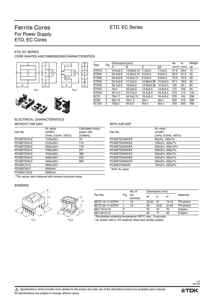 ETD-core(TDK磁芯资料).pdf