IMAQ Vision for LabVIEW User Manual
Support
Worldwide Technical Support and Product Information
National Instruments Corporate Headquarters
Worldwide Offices
Important Information
Warranty
Copyright
Trademarks
Patents
WARNING REGARDING USE OF NATIONAL INSTRUMENTS PRODUCTS
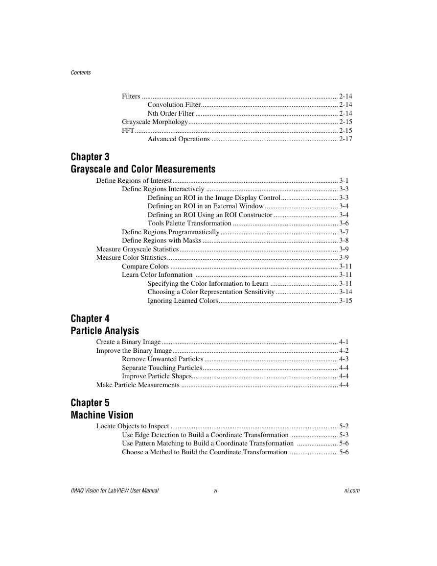
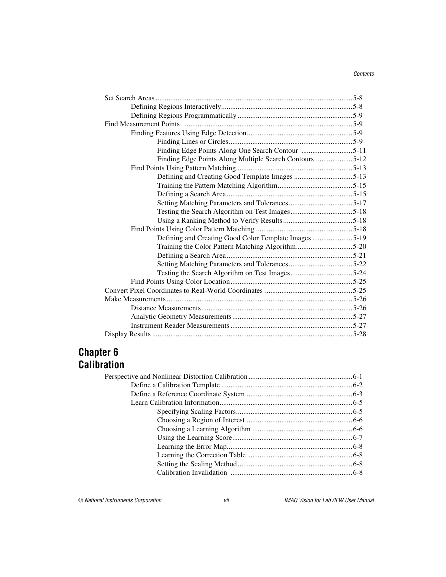
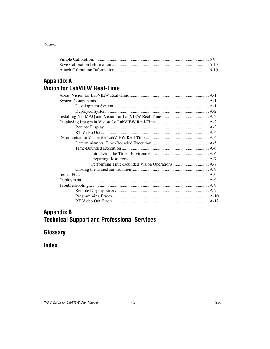
Contents
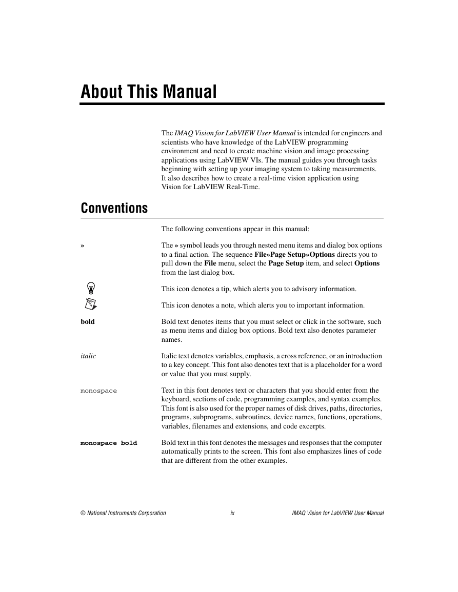
About This Manual
Conventions
Related Documentation
IMAQ Vision
NI Vision Assistant
NI Vision Builder for Automated Inspection
Other Documentation
Chapter 1 Introduction to IMAQ Vision
About IMAQ Vision
IMAQ Vision Control Palette
IMAQ Vision Function Palettes
Vision Utilities
Image Processing
Machine Vision
Creating IMAQ Vision Applications
Figure 1-1. General Steps to Designing a Vision Application
Figure 1-2. Inspection Steps for Building a Vision Application
Chapter 2 Getting Measurement-Ready Images
Set Up Your Imaging System
Calibrate Your Imaging System
Create an Image
Input and Output Combinations
Image Analysis
Image Masks
Image Filling
Image Processing
Arithmetic and Logical Operations
Acquire or Read an Image
Display an Image
External Window Display
Image Display Control
Figure 2-1. LabVIEW Image Display Control
Figure 2-2. An Image Wired into the Image Display Control Terminal
Attach Calibration Information
Analyze an Image
Improve an Image
Lookup Tables
Filters
Convolution Filter
Nth Order Filter
Grayscale Morphology
FFT
Advanced Operations
Chapter 3 Grayscale and Color Measurements
Figure 3-1. Steps for Taking Grayscale and Color Measurements
Define Regions of Interest
Table 3-1. Tools Palette Functions
Define Regions Interactively
Defining an ROI in the Image Display Control
Defining an ROI in an External Window
Defining an ROI Using an ROI Constructor
Figure 3-2. ROI Constructor
Tools Palette Transformation
Figure 3-3. Tools Palette Tools and Information
Define Regions Programmatically
Define Regions with Masks
Measure Grayscale Statistics
Measure Color Statistics
Figure 3-4. Primary Components of a Color Image
Compare Colors
Learn Color Information
Specifying the Color Information to Learn
Figure 3-5. Template Color Information
Figure 3-6. Using the Entire Image to Learn Color Distribution
Figure 3-7. Using a Single Region to Learn Color Distribution
Figure 3-8. Using Multiple Regions to Learn Color Distribution
Choosing a Color Representation Sensitivity
Ignoring Learned Colors
Chapter 4 Particle Analysis
Figure 4-1. Steps for Performing Particle Analysis
Create a Binary Image
Improve the Binary Image
Remove Unwanted Particles
Separate Touching Particles
Improve Particle Shapes
Make Particle Measurements
Chapter 5 Machine Vision
Figure 5-1. Steps for Performing Machine Vision
Locate Objects to Inspect
Use Edge Detection to Build a Coordinate Transformation
Figure 5-2. Coordinate Systems of a Reference Image and Inspection Image
Figure 5-3. Locating Coordinate System Axes with Two Search Areas
Use Pattern Matching to Build a Coordinate Transformation
Choose a Method to Build the Coordinate Transformation
Figure 5-4. Building a Coordinate Transformation
Set Search Areas
Defining Regions Interactively
Defining Regions Programmatically
Find Measurement Points
Finding Features Using Edge Detection
Finding Lines or Circles
Figure 5-5. Finding a Straight Feature
Figure 5-6. Finding a Circular Feature
Finding Edge Points Along One Search Contour
Finding Edge Points Along Multiple Search Contours
Find Points Using Pattern Matching
Defining and Creating Good Template Images
Figure 5-7. Symmetry
Figure 5-8. Feature Detail
Figure 5-9. Positional Information
Figure 5-10. Background Information
Training the Pattern Matching Algorithm
Defining a Search Area
Figure 5-11. Selecting a Search Area for Grayscale Pattern Matching
Setting Matching Parameters and Tolerances
Testing the Search Algorithm on Test Images
Using a Ranking Method to Verify Results
Find Points Using Color Pattern Matching
Defining and Creating Good Color Template Images
Training the Color Pattern Matching Algorithm
Defining a Search Area
Figure 5-12. Selecting a Search Area for Color Pattern Matching
Setting Matching Parameters and Tolerances
Testing the Search Algorithm on Test Images
Find Points Using Color Location
Convert Pixel Coordinates to Real-World Coordinates
Make Measurements
Distance Measurements
Analytic Geometry Measurements
Instrument Reader Measurements
Display Results
Chapter 6 Calibration
Perspective and Nonlinear Distortion Calibration
Define a Calibration Template
Figure 6-1. Defining a Calibration Grid
Define a Reference Coordinate System
Figure 6-2. Axis Direction in the Image Plane
Figure 6-3. A Calibration Grid and an Image of the Grid
Figure 6-4. Defining a Coordinate System
Learn Calibration Information
Specifying Scaling Factors
Choosing a Learning Algorithm
Choosing a Region of Interest
Figure 6-5. Types of Image Distortion
Figure 6-6. Calibration ROIs
Using the Learning Score
Learning the Error Map
Learning the Correction Table
Setting the Scaling Method
Calibration Invalidation
Simple Calibration
Figure 6-7. Defining a Simple Calibration
Save Calibration Information
Attach Calibration Information
Appendix A Vision for LabVIEW Real-Time
Appendix B Technical Support and Professional Services
Glossary
Numbers/Symbols
A
B
C
D-E
F-G
H
I
J-L
M-N
O
P
Q-R
S
T-V
Index
A-C
D-G
H-I
K-L
M-N
O-S
T-W


 2023年江西萍乡中考道德与法治真题及答案.doc
 2012年重庆南川中考生物真题及答案.doc
 2013年江西师范大学地理学综合及文艺理论基础考研真题.doc
 2020年四川甘孜小升初语文真题及答案I卷.doc
 2020年注册岩土工程师专业基础考试真题及答案.doc
 2023-2024学年福建省厦门市九年级上学期数学月考试题及答案.doc
 2021-2022学年辽宁省沈阳市大东区九年级上学期语文期末试题及答案.doc
 2022-2023学年北京东城区初三第一学期物理期末试卷及答案.doc
 2018上半年江西教师资格初中地理学科知识与教学能力真题及答案.doc
 2012年河北国家公务员申论考试真题及答案-省级.doc
 2020-2021学年江苏省扬州市江都区邵樊片九年级上学期数学第一次质量检测试题及答案.doc
 2022下半年黑龙江教师资格证中学综合素质真题及答案.doc