Multimed Tools Appl (2018) 77:13721–13752
DOI 10.1007/s11042-017-4986-1
An IWT based blind and robust image watermarking
scheme using secret key matrix
Kshiramani Naik1 · Saswati Trivedy1 ·
Arup Kumar Pal1
Received: 18 October 2016 / Revised: 20 April 2017 / Accepted: 25 June 2017 /
Published online: 1 September 2017
© Springer Science+Business Media, LLC 2017
Abstract In this paper, the authors have proposed a binary watermark embedding approach
for protecting the copyright ownership of the gray-scale images. The proposed watermark
embedding process is realized in integer wavelet transform (IWT) domain to defend the
robustness property. Instead of inserting the watermark bits directly in the coefficients
of cover media, an indirect embedding mechanism is proposed with the reference to a
logistic map based secret key matrix which enhance the secrecy of the proposed embed-
ding approach. Initially, the approximate sub band of the IWT transformed cover image is
selected with the intention to embed the watermark. Later, a secret key matrix of size cor-
responding to the approximate sub band of the cover image is formed using the logistic
map with secret parameters. During the watermark embedding process, the approximate sub
band is modified indirectly with reference to the secret key matrix and a proposed division
table. The scheme is tested on a set of standard images and satisfactory results are achieved.
In addition, the proposed schemes is also able to extract the watermark information in blind
manner. Also, the scheme is comparable with some other related schemes. Finally, the pro-
posed watermarking scheme is able to survive the watermark even after performing certain
types of image manipulation attacks.
Keywords Blind watermarking · Copyright protection · Integer wavelet transform ·
Logistic map · Robust watermarking
Kshiramani Naik
kshiramani@gmail.com
Saswati Trivedy
saswatialo12@gmail.com
Arup Kumar Pal
arupkrpal@gmail.com
1 Department of Computer Science and Engineering, Indian Institute of Technology (ISM) Dhanbad,
Jharkhand 826004, India
�
13722
1 Introduction
Multimed Tools Appl (2018) 77:13721–13752
The extensive evolution of digital technology facilitates the multimedia data to be transmit-
ted and distributed in digital format over the Internet. As digital data are easily exposed to
illegal possession, duplication and dissemination over the Internet, it has become an essen-
tial to think about the copyright protection, ownership verification, and tamper-resistance of
digital data during their applications. Digital watermarking method is one of the widely used
solution for detecting the illegal manipulation occurred in digital data. In digital watermark-
ing method, the information related to the digital data is embedded or hidden in the digital
data itself such that the authenticity and integrity can be verified by extracting or detecting
the embedded information. The embedded information is termed as watermark. The digital
data that contain watermark is termed as cover media. Depending upon the cover media, the
watermarking schemes are classified as image, video or audio watermarking.
Depending upon the specific goal, the watermarking method can be categorized into
robust, semi-fragile and fragile watermarking. The robust watermarking method is gen-
erally considered for copyright protection of the digital data [17, 18]. In robust water-
marking scheme, the existence of secret information can be known but it is hard to
remove/manipulate the secret information [8]. So in copy right protection scheme robust
watermarking is preferred.
Depending upon the embedding domain, again the robust watermarking schemes can be
divided into two categories, i.e., spatial-domain schemes and frequency-domain schemes. In
Spatial domain, watermark is added directly by modifying pixel values of the cover image.
Several robust watermarking scheme in spatial domain have been devised by researchers
[10, 15–17, 21]. Embedding the watermark into the cover image in spatial domain is a
straight forward method, which has the advantages of low computational complexity and
easy implementation. However, the most serious problem of spatial domains is the weakness
of robustness i.e. spatial domain watermarking algorithms is able to resist some limited
number of attacks. In transform domain, the watermark is embedded by modulating the
coefficients of the transformed cover image. However in case of frequency-domain scheme,
the computational cost is higher than the ones based on spatial domain, more information
can be embedded and better robustness against the common image processing attacks can
be survived. The main advantages of using the frequency domain methods are that they
can easily be adapted to lossy compression systems, which have the ability to embed data
in the compressed representations, and have ability to reveal the watermark even from the
modified watermarked image [9, 20]. The transform domain based watermarking schemes
can be implemented through various transformation tools such as discrete cosine transform
(DCT) [22], discrete wavelet transform (DWT) [23], Discrete Fourier transform(DFT) [12],
Integer wavelet transform(IWT) [4], Singular Value Decomposition(SVD) [11] etc.
Various robust image watermarking schemes based on transform domain have shown
their effectiveness in image data protection. In [24], Thabit et al. proposed another water-
marking scheme based on Slantlet transform matrix to transform small blocks of the original
image and hiding the watermark bits by modifying the mean values of the carrier sub-
bands. Fazli et al. [7] proposed a robust watermarking based on a combination of DWT,
DCT, and SVD domains. This paper mainly focuses on the geometric attacks. To address
this goal, the host image is divided into four non overlapping rectangular segments called
sub-images and then watermark is independently embedded into each of them, using the
hybrid scheme. The redundancy reduces effect of cropping attack. Moreover, in order to
correct main geometric attacks, such as rotation, translation, and affine translation, an inven-
tional synchronization technique is utilized to recover the geometrically attacked image
�
Multimed Tools Appl (2018) 77:13721–13752
13723
via detection of desired image corners. A binary image in the first experiment and some
1D binary random sequences with different lengths in the next experiments are used as
watermarks. Weng et al. proposed another method based on integer Haar wavelet transform
(IHWT), which utilizes block selection and difference expansion (DE) (or histogram shift-
ing (HS)) [28]. IHWT has the characteristic that the average of a block remains unchanged
before and after watermark embedding. Hence, this invariability can be used for determin-
ing whether a block is located in a smooth region or not. In [19], Pal et al. proposed a
robust and blind watermarking scheme based on Discrete Cosine Transform (DCT) for pro-
tecting the copyright ownership of the digital images. In this work a binary watermark is
embedded into the block based DCT transformed cover image by modifying the middle
significant AC coefficients using repetition code. The proposed approach ensures the pro-
tection of copyright information even in compressed form of the watermarked image. In
[13], Kumsawat et al., the watermark has been embeded into the DMT coefficients using
multiwavelet tree techniques. Digital watermarking algorithm using integer wavelet trans-
form(IWT) have received wide range of attention in the recent years due to the property
that it can map integer to integer without the rounding error, and can obtain good imper-
ceptibility . There are many IWT-based watermarking schemes that have been proposed in
recent years. In [25], Verma et al. designed robust digital watermarking scheme using 3-
level lifting wavelet transform (LWT) with a block selection procedure. Non-overlapping
coefficient blocks from the low pass subband are selected after applying LWT and using cer-
tain criterion based on minimum coefficient difference and a threshold value. Ansari et al.
proposed another watermarking scheme using IWT and SVD (singular value decomposi-
tion) based to address false positive problem that are suffered in SVD based watermarking
techniques [3]. The properties of IWT and SVD help in achieving high value of robust-
ness. Singular values are used for the watermark embedding. In order to further improve
the quality of watermarking, the optimization of scaling factor (mixing ratio) is performed
with the help of artificial bee colony (ABC) algorithm. In [26], Wang et al. proposed an
efficient integer transform based reversible watermarking scheme. In this paper, Tian’s dif-
ference expansion (DE) technique can be reformulated as an integer transform. Then, a
generalized integer transform and a payload-dependent location map are constructed to
extend the DE technique to the pixel blocks of arbitrary length. In [5], Bohra et al. pro-
posed a technique for robust watermarking of images based on lifting-based integer wavelet
transform. The proposed scheme, along with its robustness has got the capability of blind
self–authentication of the watermarked images. This paper also utilizes histogram modifi-
cation to avoid overflow/underflow problem. In [6], the 2-level IWT based watermarking
scheme for embedding the compressed version of the binary watermark logo has been devel-
oped for robust watermarking. In this paper, the source document image is divided into
empty and non-empty segments depending on the absence or presence of the information.
Watermarking is applied for non-empty segments. A binary watermark logo is compressed
using binary block coding technique of appropriate block-size. IWT is applied on the non-
empty segment of the source document image. LL-sub–band of the transformed image is
subdivided into blocks of uniform size and compressed watermark bit stream is embedded
into it. In [14], Lingamgunta et al. proposed a reversible watermarking based on IWT. The
proposed algorithm hides the data and the bookkeeping information in the high frequency
subbands of CDF (2,2) integer wavelet coefficients whose magnitudes are similar to a cer-
tain predefined threshold. Histogram modification is applied as a preprocessing to prevent
overflow/underflow. The embedding technique is based on the parent–child structure of the
transformed coefficients called “quadruple wavelet tree” (QWT). In this paper, we develop
an invisible robust watermarking scheme based on 1–level IWT domain. Robustness and
�
13724
Multimed Tools Appl (2018) 77:13721–13752
imperceptibility are strongly achieved in the proposed method through the characteristics
of IWT. Before watermark embedding, the cover image is transformed through IWT. We
have selected the approximate sub band of the integr wavelet transformed cover image for
the watermark insertion. Generally watermark embedding only in the approximate sub band
reduce the chance of removing or destroying the watermark from the watermarked image.
In [27], Wang et al. proposed a 3-level wavelet based intelligent watermarking scheme
using particle swarm optimization (PSO) technique. In this scheme, the high sub–bands of
the DWT transformed cover image are considered. The coefficents to contains watermark
bits are selected randomly from the different sub–bands. Ali & Ahn presented a DWT–
SVD based watermarking algorithm where self-adaptive differential evolution algorithm is
used during embedding process [1]. Another work is presented by Ali et al was in wavelet
domain and SVD domain. In this work the low frequency sub–band is selected and divided
into blocks. Again the blocks were SVD transformed and the left and right singular vector
matrix are used for watermark embedding using artificial bee colony (ABC) algorithm [2].
In some existing schemes, the watermark bits are embedded directly on the selected
coefficients of the cover image. But in the proposed watermarking scheme, instead of
embedding the watermark bits directly to the coefficients of the cover image, an indi-
rect method corresponds to a division method is utilized. However watermark embedding
only in the low subband increase the chance of removing or destroying the watermark
with the attempt of tampering of that portion. Although this proposed method utilize the
low sub–band of the transformed cover image, robustness and imperceptibility are strongly
achieved through the proposed embedding method and the characteristics of IWT. Also
to increase watermarking security, a generated key matrix using logistic is utilized. The
intention of the proposed method is to improve the robustness and invisibility of the water-
marked image and this scheme is suitable for extract the watermark information in a blind
manner.
The rest of the paper is organized as follows. Section 2 describes the related fundamentals
for better understanding of the proposed method. Section 3 contains the details of the pro-
posed method. The experimental results and discussion are in Section 4. Section 5 contains
the conclusion of the work done in this paper.
2 Preliminaries
2.1 Integer to integer wavelet transform
Due to the multi-resolution characteristic, the conventional wavelet transform is very popu-
lar in signal and image processing field. Also it is a very good computational tool to reduce
the digital image files with higher compression ratios which helps to storing images using
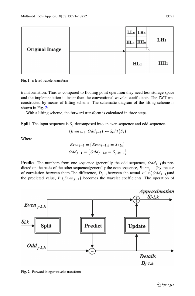
less memory and for transmitting images faster and more reliably. In the Fig. 1, LL sub-
band represents the approximation part of the image and LH, HH, HL represents the detail
part of the image. But the conventional Wavelet transform is not suitable for truly loss-
less coding because it gives floating point results for any input sequence which generally
create problem for reconstruction of the exact signal or image. Due to this problems, a gen-
eralized version of conventional wavelet transform, Integer to Integer Wavelet Transform
(IWT) is very popular for lossless coding method. It is also known as the second generation
of the wavelet transform. The IWT was introduced by Sweldens (1998). The IWT inherits
the multi-resolution characteristics of the conventional wavelet transform and that can map
integer input sequence to integer output sequence by rounding off the values of wavelet
�
Multimed Tools Appl (2018) 77:13721–13752
13725
Fig. 1 n-level wavelet transform
transformation. Thus as compared to floating point operation they need less storage space
and the implementation is faster than the conventional wavelet coefficients. The IWT was
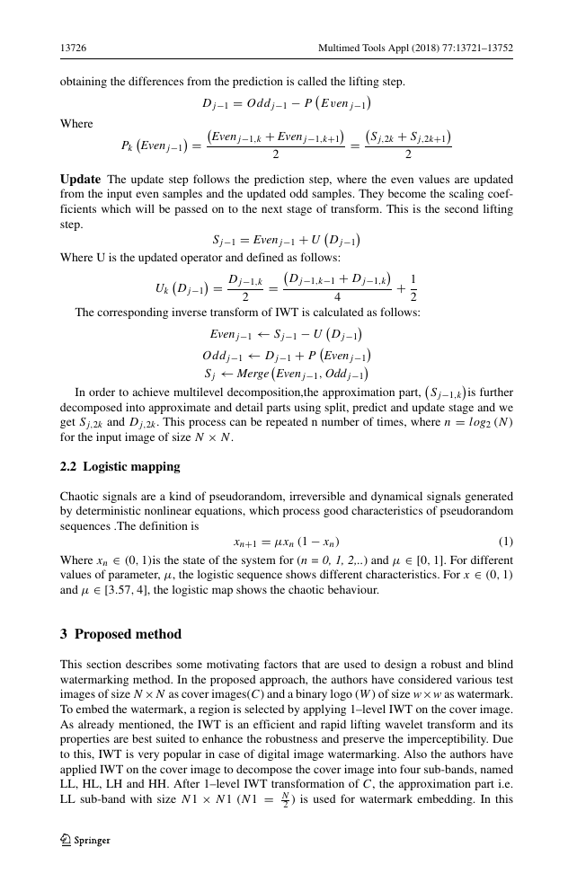
constructed by means of lifting scheme. The schematic diagram of the lifting scheme is
shown in Fig. 2:
With a lifting scheme, the forward transform is calculated in three steps.
Split The input sequence is Sj decomposed into an even sequence and odd sequence.
Where
← Split
Sj
Evenj−1, Oddj−1
Evenj−1 =
Oddj−1 =
Evenj−1,k = Sj,2k
Oddj−1,k = Sj,2k+1
Predict The numbers from one sequence (generally the odd sequence, Oddj−1)is pre-
dicted on the basis of the other sequence(generally the even sequence, Evenj−1 )by the use
of correlation between them.The difference, Dj−1between the actual value
and
the predicted value, P
becomes the wavelet coefficients. The operation of
Oddj−1
Evenj−1
Fig. 2 Forward integer wavelet transform
�
13726
Multimed Tools Appl (2018) 77:13721–13752
obtaining the differences from the prediction is called the lifting step.
Where
Pk
Evenj−1
=
Dj−1 = Oddj−1 − P
Evenj−1,k + Evenj−1,k+1
Evenj−1
2
=
Sj,2k + Sj,2k+1
2
Update The update step follows the prediction step, where the even values are updated
from the input even samples and the updated odd samples. They become the scaling coef-
ficients which will be passed on to the next stage of transform. This is the second lifting
step.
Sj−1 = Evenj−1 + U
Dj−1
Where U is the updated operator and defined as follows:
+ 1
2
The corresponding inverse transform of IWT is calculated as follows:
= Dj−1,k
Dj−1
=
Uk
2
4
Dj−1,k−1 + Dj−1,k
Evenj−1 ← Sj−1 − U
Oddj−1 ← Dj−1 + P
Sj ← Merge
Dj−1
Evenj−1
Evenj−1, Oddj−1
In order to achieve multilevel decomposition,the approximation part,
is further
decomposed into approximate and detail parts using split, predict and update stage and we
get Sj,2k and Dj,2k. This process can be repeated n number of times, where n = log2 (N )
for the input image of size N × N.
Sj−1,k
2.2 Logistic mapping
Chaotic signals are a kind of pseudorandom, irreversible and dynamical signals generated
by deterministic nonlinear equations, which process good characteristics of pseudorandom
sequences .The definition is
(1)
Where xn ∈ (0, 1)is the state of the system for (n = 0, 1, 2,..) andμ ∈ [0, 1]. For different
values of parameter, μ, the logistic sequence shows different characteristics. For x ∈ (0, 1)
and μ ∈ [3.57, 4], the logistic map shows the chaotic behaviour.
xn+1 = μxn (1 − xn)
3 Proposed method
This section describes some motivating factors that are used to design a robust and blind
watermarking method. In the proposed approach, the authors have considered various test
images of size N×N as cover images(C) and a binary logo (W ) of sizew ×w as watermark.
To embed the watermark, a region is selected by applying 1–level IWT on the cover image.
As already mentioned, the IWT is an efficient and rapid lifting wavelet transform and its
properties are best suited to enhance the robustness and preserve the imperceptibility. Due
to this, IWT is very popular in case of digital image watermarking. Also the authors have
applied IWT on the cover image to decompose the cover image into four sub-bands, named
LL, HL, LH and HH. After 1–level IWT transformation of C, the approximation part i.e.
LL sub-band with size N1 × N1 (N1 = N
2 ) is used for watermark embedding. In this
�
Multimed Tools Appl (2018) 77:13721–13752
13727
paper, LL sub-band is termed as CA. Before embedding the watermark, the CA part is
decomposed into non-overlapping blocks of size n× n. In the proposed method, the authors
consider the block based watermark embedding procedure. To preserve the watermark bit
unchanged, a single bit is embedded repeatedly in the selected coefficients of a particular
block. Before embedding process some binary key vectors are generated using a division
method (explained in the Key Generation phase) for watermark bit embedding. These binary
key vectors are generated from a key matrix generated by utilizing the chaotic logistic map.
This binary key also utilized to select the coefficients to be embedded in each block. The
detail procedure of the proposed method is carried out through three phases as follows:
3.1 Pre-processing phase
This phase again comprises of two parts. In the first part a key matrix of same size as CA is
generated from the chaotic logistic map. Here, instead of taking the direct values of initial
condition and system parameter, the authors have considers the calculated initial value and
system parameter to generate the logistic sequence. The key matrix is used to generate the
binary key vectors those are used for watermark embedding. In the next part the detail
procedure of required binary key vectors is described.
Key generation using logistic map
Step 1: Generate a random binary key sequence of l bits long, where l = t 2.
Step 2: Divide the key sequence into blocks of 16-bit each.
K = σ1σ2.....σ16
Step 3: To calculate the initial condition (x0) and the system parameter (μ) of the chaotic
logistic map, the ASCII key sequence is used. The intermediate values, γ1 and
γ2 are used to calculate the initial condition and γ3, γ4 are used to calculate the
system parameter.
Where
, 1
1000
μ = mod
x0 = mod ((γ1 + γ2) , 2)
3.999 + (γ3 + γ4)
γ1 = (σ1 σ2 σ3)10
223 ,
γ2 = (σ4 σ5 σ6)10
223 ,
γ3 = (σ7 σ8 σ9)10
223 ,
γ4 = (σ10 σ11 σ12)10
223
Step 4: Generate a chaotic sequence, a of length l by using the (1).
Step 5: Reshape the generated chaotic sequence into a square matrix of size t × t.
Step 6: The matrix is concatenated in raster scan order to generate the matrix K EM of
size CA i.e N1 × N1.
Binary key vectors generation for watermark embedding
This phase generates the binary keys for the individual block of the decomposed CA. The
detail procedure is described as follows:
Step 1: Calculate the difference matrix, D using CA sub–band and K EM.
D = |CA − K EM|
�
13728
Multimed Tools Appl (2018) 77:13721–13752
Step 2: Divide the difference matrix, D into the non overlapping blocks, b of size, n × n.
b =
b1, b2, ....., b N12
n2
Step 3: Convert each block into row vector.
d =
d1×n2 , d2×n2 , ......, d N12
n2
× n2
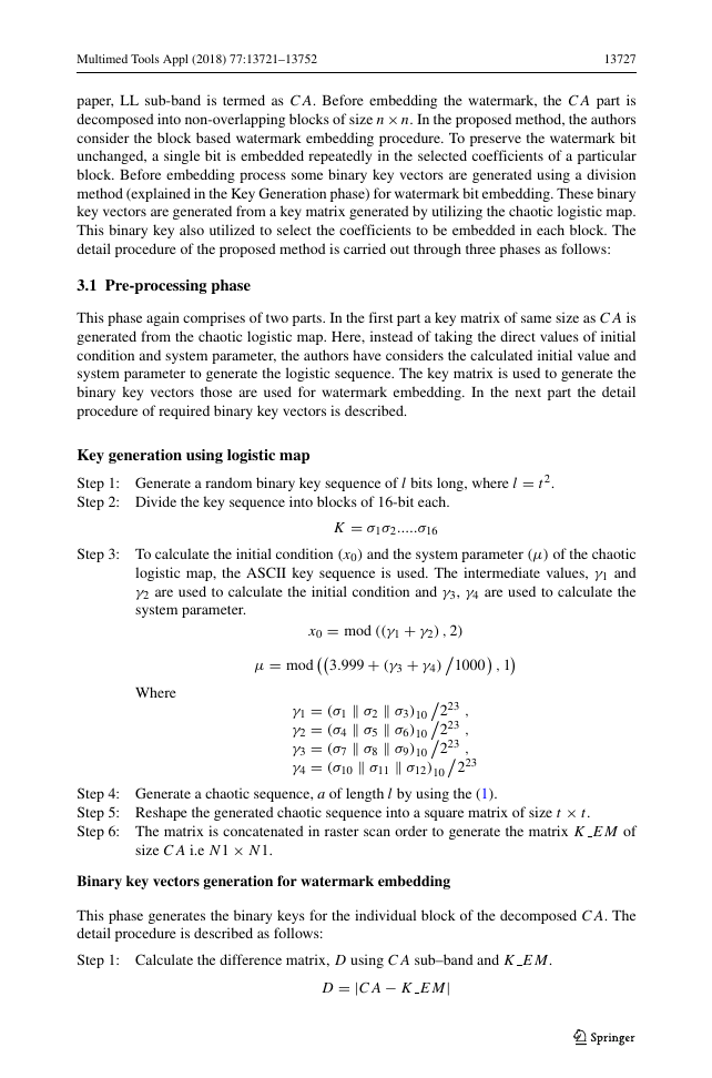
For Example Suppose A is the one of the decomposed block of difference matrix, D.
Then A is converted into row vector as shown below.
Step 4: Calculate the adjacent differences, Adj Diff in each row using the following
formula
For i = 1 : 2 : N12
n2
− 1
Adj diff (i) = abs(di − di+1)
Binary Value Generation using Division Method
Step 5: Take a range, R with minimum value, min and maximum value, max. As we are
considering gray test images so min = 0 and max = 255.
Step 6: Divide R with r number of divisions to give r slots.
R = {R1, R2, .......Rr}
Then
Where R1 = min and Rr = max
Step 7: Then the elements of Binary key vectors, Bin CA(i) reference to the individual
block matrix of CA can be generated from the R and Adj diff (i) as follows:
Bin CA(j ) =
⎧
⎪⎪⎪⎪⎨
⎪⎪⎪⎪⎩
1
0
if Rk ≤ Adj diff(j) ≤ Rk+1
and mod (k, 2) == 1
if Rk ≤ Adj diff(j) ≤ Rk+1
and mod (k, 2) == 0
(2)
Where k = 1 : r and j = 1 : 2 : n2
For example:
Suppose r = 20, the range can be divided into different slots as shown in Fig. 3.
The main objective of the generation of the binary key vectors space is to utilize these
keys as the reference to the coefficients that are to be modified. The utilization of these
reference bits are explained in the next section.
�


 2023年江西萍乡中考道德与法治真题及答案.doc
 2012年重庆南川中考生物真题及答案.doc
 2013年江西师范大学地理学综合及文艺理论基础考研真题.doc
 2020年四川甘孜小升初语文真题及答案I卷.doc
 2020年注册岩土工程师专业基础考试真题及答案.doc
 2023-2024学年福建省厦门市九年级上学期数学月考试题及答案.doc
 2021-2022学年辽宁省沈阳市大东区九年级上学期语文期末试题及答案.doc
 2022-2023学年北京东城区初三第一学期物理期末试卷及答案.doc
 2018上半年江西教师资格初中地理学科知识与教学能力真题及答案.doc
 2012年河北国家公务员申论考试真题及答案-省级.doc
 2020-2021学年江苏省扬州市江都区邵樊片九年级上学期数学第一次质量检测试题及答案.doc
 2022下半年黑龙江教师资格证中学综合素质真题及答案.doc