Journal of Materials Processing Technology 164–165 (2005) 1459–1465
Programmable controller designed for electro-pneumatic systems夽
J. ´Swider a, G. Wszołek a,∗
, W. Carvalho b
a Department of Engineering Processes, Automation and Integrated Manufacturing Systems, Faculty of Mechanical Engineering,
Silesian University of Technology, 44–100 Gliwice, Poland
b Polytechnic School from the University of S˜ao Paulo, CEP 05508-900, S˜ao Paulo/SP, Brazil
Abstract
This project deals with the study of electro-pneumatic systems and the programmable controller that provides an effective and easy way
to control the sequence of the pneumatic actuators movement and the states of pneumatic system. The project of a specific controller for
pneumatic applications join the study of automation design and the control processing of pneumatic systems with the electronic design based
on microcontrollers to implement the resources of the controller.
© 2005 Elsevier B.V. All rights reserved.
Keywords: Programmable controller; Microcontroller; Electro-pneumatic; Automation
1. Introduction
The automation systems that use electro-pneumatic tech-
nology are formed mainly by three kinds of elements: ac-
tuators or motors, sensors or buttons and control elements
like valves. Nowadays, most of the control elements used to
execute the logic of the system were substituted by the Pro-
grammable Logic Controller (PLC). Sensors and switches
are plugged as inputs and the direct control valves for the ac-
tuators are plugged as outputs. An internal program executes
all the logic necessary to the sequence of the movements,
simulates other components like counter, timer and control
the status of the system.
With the use of the PLC, the project wins agility, because
it is possible to create and simulate the system as many times
as needed. Therefore, time can be saved, risk of mistakes
reduced and complexity can be increased using the same el-
ements.
A conventional PLC, that is possible to find on the mar-
ket from many companies, offers many resources to control
not only pneumatic systems, but all kinds of system that uses
夽 This work has been conducted as a part of the research project no. 4
T07C 01827 supported by the Committee of Scientific Research in years
2004–2006.
∗
Corresponding author.
E-mail address: grzegorz.wszolek@polsl.pl (G. Wszołek).
0924-0136/$ – see front matter © 2005 Elsevier B.V. All rights reserved.
doi:10.1016/j.jmatprotec.2005.02.200
electrical components. The PLC can be very versatile and ro-
bust to be applied in many kinds of application in the industry
or even security system and automation of buildings.
Because of those characteristics, in some applications
the PLC offers to much resources that are not even used
to control the system, electro-pneumatic system is one of
this kind of application. The use of PLC, especially for
small size systems, can be very expensive for the automation
project.
An alternative in this case is to create a specific controller
that can offer the exactly size and resources that the project
needs [3,4]. This can be made using microcontrollers as the
base of this controller.
The controller, based on microcontroller, can be very spe-
cific and adapted to only one kind of machine or it can work as
a generic controller that can be programmed as a usual PLC
and work with logic that can be changed. All these charac-
teristics depend on what is needed and how much experi-
ence the designer has with developing an electronic circuit
and firmware for microcontroller. But the main advantage of
design the controller with the microcontroller is that the de-
signer has the total knowledge of his controller, which makes
it possible to control the size of the controller, change the
complexity and the application of it. It means that the project
gets more independence from other companies, but at the
same time the responsibility of the control of the system stays
at the designer hands.
�
1460
J. ´Swider et al. / Journal of Materials Processing Technology 164–165 (2005) 1459–1465
2. Electro-pneumatic system
On automation system one can find three basic compo-
nents mentioned before, plus a logic circuit that controls the
system. An adequate technique is needed to project the logic
circuit and integrate all the necessary components to execute
the sequence of movements properly.
For a simple direct sequence of movement an intuitive
method can be used [1,5], but for indirect or more complex
sequences the intuition can generate a very complicated cir-
cuit and signal mistakes. It is necessary to use another method
that can save time of the project, make a clean circuit, can
eliminate occasional signal overlapping and redundant cir-
cuits.
The presented method is called step-by-step or algorithmic
[1,5], it is valid for pneumatic and electro-pneumatic systems
and it was used as a base in this work. The method consists
of designing the systems based on standard circuits made for
each change on the state of the actuators, these changes are
called steps.
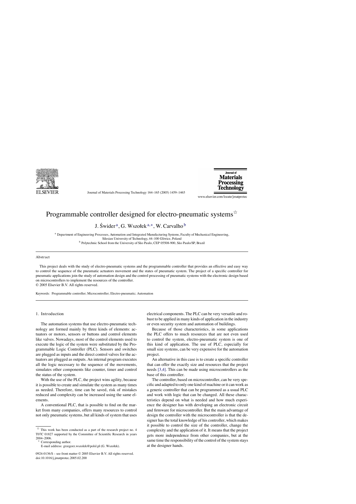
Fig. 1. Standard circuit for the pneumatic system.
The first part is to design those kinds of standard circuits
for each step, the next task is to link the standard circuits and
the last part is to connect the control elements that receive
signals from sensors, switches and the previous movements,
and give the air or electricity to the supply lines of each step.
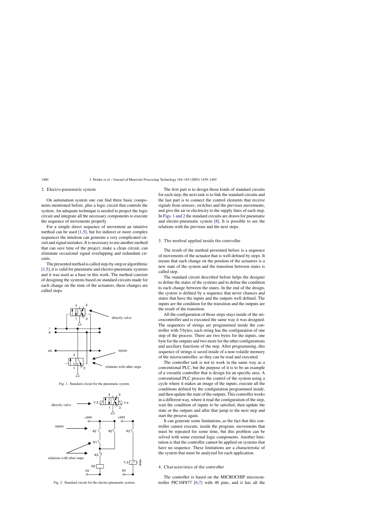
In Figs. 1 and 2 the standard circuits are drawn for pneumatic
and electro-pneumatic system [8]. It is possible to see the
relations with the previous and the next steps.
3. The method applied inside the controller
The result of the method presented before is a sequence
of movements of the actuator that is well defined by steps. It
means that each change on the position of the actuators is a
new state of the system and the transition between states is
called step.
The standard circuit described before helps the designer
to define the states of the systems and to define the condition
to each change between the states. In the end of the design,
the system is defined by a sequence that never chances and
states that have the inputs and the outputs well defined. The
inputs are the condition for the transition and the outputs are
the result of the transition.
All the configuration of those steps stays inside of the mi-
crocontroller and is executed the same way it was designed.
The sequences of strings are programmed inside the con-
troller with 5 bytes; each string has the configuration of one
step of the process. There are two bytes for the inputs, one
byte for the outputs and two more for the other configurations
and auxiliary functions of the step. After programming, this
sequence of strings is saved inside of a non-volatile memory
of the microcontroller, so they can be read and executed.
The controller task is not to work in the same way as a
conventional PLC, but the purpose of it is to be an example
of a versatile controller that is design for an specific area. A
conventional PLC process the control of the system using a
cycle where it makes an image of the inputs, execute all the
conditions defined by the configuration programmed inside,
and then update the state of the outputs. This controller works
in a different way, where it read the configuration of the step,
wait the condition of inputs to be satisfied, then update the
state or the outputs and after that jump to the next step and
start the process again.
It can generate some limitations, as the fact that this con-
troller cannot execute, inside the program, movements that
must be repeated for some time, but this problem can be
solved with some external logic components. Another limi-
tation is that the controller cannot be applied on systems that
have no sequence. These limitations are a characteristic of
the system that must be analyzed for each application.
4. Characteristics of the controller
Fig. 2. Standard circuit for the electro-pneumatic system.
The controller is based on the MICROCHIP microcon-
troller PIC16F877 [6,7] with 40 pins, and it has all the
�
J. ´Swider et al. / Journal of Materials Processing Technology 164–165 (2005) 1459–1465
1461
Table 1
Resources of the controller
Digital inputs
Digital outputs
Analog inputs
Internal timers
Parallel circuits
Lines of steps
8
8
1
2
2
48
resources needed for this project. It has enough pins for all the
components, serial communication implemented in circuit,
EEPROM memory to save all the configuration of the system
and the sequence of steps. For the execution of the main
program, it offers complete resources as timers and interrup-
tions.
The list of resources of the controller was created to ex-
plore all the capacity of the microcontroller to make it as
complete as possible. During the step, the program chooses
how to use the resources reading the configuration string of
the step. This string has two bytes for digital inputs, one used
as a mask and the other one used as a value expected. One
byte is used to configure the outputs value. One bytes more is
used for the internal timer, the analog input or time-out. The
EEPROM memory inside is 256 bytes length that is enough
to save the string of the steps, with this characteristic it is
possible to save between 48 steps (Table 1).
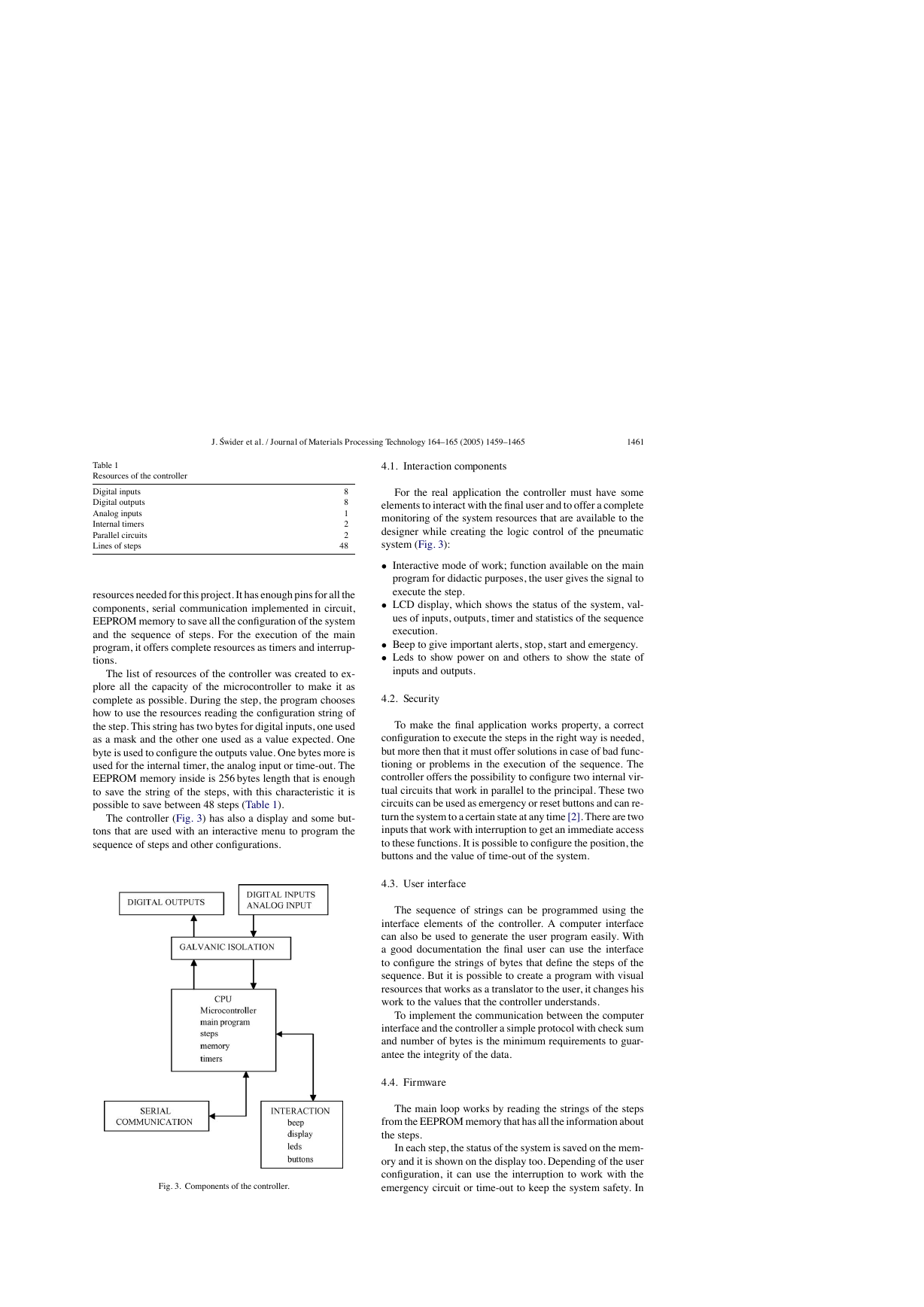
The controller (Fig. 3) has also a display and some but-
tons that are used with an interactive menu to program the
sequence of steps and other configurations.
Fig. 3. Components of the controller.
4.1. Interaction components
For the real application the controller must have some
elements to interact with the final user and to offer a complete
monitoring of the system resources that are available to the
designer while creating the logic control of the pneumatic
system (Fig. 3):
• Interactive mode of work; function available on the main
program for didactic purposes, the user gives the signal to
execute the step.
• LCD display, which shows the status of the system, val-
ues of inputs, outputs, timer and statistics of the sequence
execution.
• Beep to give important alerts, stop, start and emergency.
• Leds to show power on and others to show the state of
inputs and outputs.
4.2. Security
To make the final application works property, a correct
configuration to execute the steps in the right way is needed,
but more then that it must offer solutions in case of bad func-
tioning or problems in the execution of the sequence. The
controller offers the possibility to configure two internal vir-
tual circuits that work in parallel to the principal. These two
circuits can be used as emergency or reset buttons and can re-
turn the system to a certain state at any time [2]. There are two
inputs that work with interruption to get an immediate access
to these functions. It is possible to configure the position, the
buttons and the value of time-out of the system.
4.3. User interface
The sequence of strings can be programmed using the
interface elements of the controller. A computer interface
can also be used to generate the user program easily. With
a good documentation the final user can use the interface
to configure the strings of bytes that define the steps of the
sequence. But it is possible to create a program with visual
resources that works as a translator to the user, it changes his
work to the values that the controller understands.
To implement the communication between the computer
interface and the controller a simple protocol with check sum
and number of bytes is the minimum requirements to guar-
antee the integrity of the data.
4.4. Firmware
The main loop works by reading the strings of the steps
from the EEPROM memory that has all the information about
the steps.
In each step, the status of the system is saved on the mem-
ory and it is shown on the display too. Depending of the user
configuration, it can use the interruption to work with the
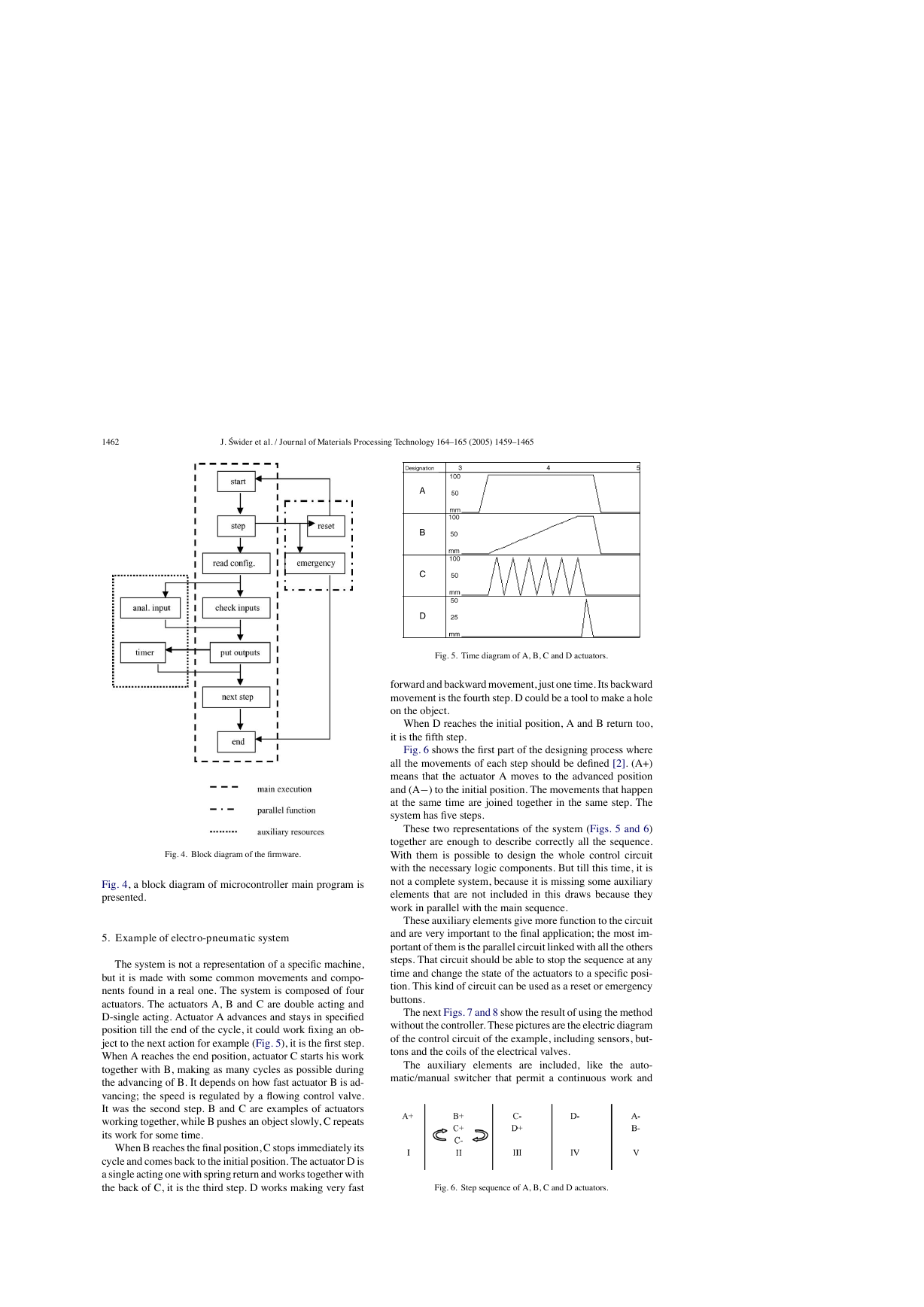
emergency circuit or time-out to keep the system safety. In
�
1462
J. ´Swider et al. / Journal of Materials Processing Technology 164–165 (2005) 1459–1465
Fig. 5. Time diagram of A, B, C and D actuators.
forward and backward movement, just one time. Its backward
movement is the fourth step. D could be a tool to make a hole
on the object.
When D reaches the initial position, A and B return too,
it is the fifth step.
Fig. 6 shows the first part of the designing process where
all the movements of each step should be defined [2]. (A+)
means that the actuator A moves to the advanced position
and (A−) to the initial position. The movements that happen
at the same time are joined together in the same step. The
system has five steps.
These two representations of the system (Figs. 5 and 6)
together are enough to describe correctly all the sequence.
With them is possible to design the whole control circuit
with the necessary logic components. But till this time, it is
not a complete system, because it is missing some auxiliary
elements that are not included in this draws because they
work in parallel with the main sequence.
These auxiliary elements give more function to the circuit
and are very important to the final application; the most im-
portant of them is the parallel circuit linked with all the others
steps. That circuit should be able to stop the sequence at any
time and change the state of the actuators to a specific posi-
tion. This kind of circuit can be used as a reset or emergency
buttons.
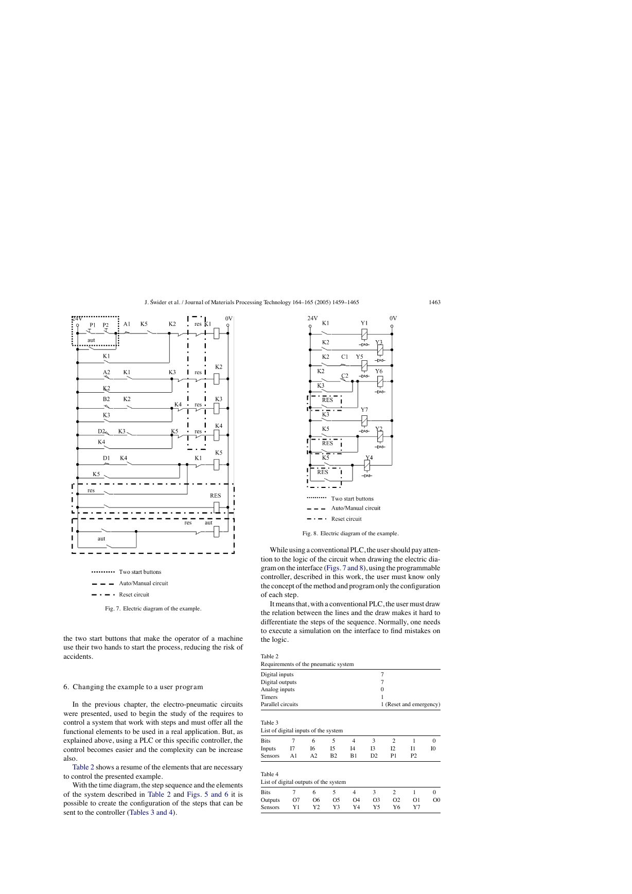
The next Figs. 7 and 8 show the result of using the method
without the controller. These pictures are the electric diagram
of the control circuit of the example, including sensors, but-
tons and the coils of the electrical valves.
The auxiliary elements are included,
like the auto-
matic/manual switcher that permit a continuous work and
Fig. 6. Step sequence of A, B, C and D actuators.
Fig. 4. Block diagram of the firmware.
Fig. 4, a block diagram of microcontroller main program is
presented.
5. Example of electro-pneumatic system
The system is not a representation of a specific machine,
but it is made with some common movements and compo-
nents found in a real one. The system is composed of four
actuators. The actuators A, B and C are double acting and
D-single acting. Actuator A advances and stays in specified
position till the end of the cycle, it could work fixing an ob-
ject to the next action for example (Fig. 5), it is the first step.
When A reaches the end position, actuator C starts his work
together with B, making as many cycles as possible during
the advancing of B. It depends on how fast actuator B is ad-
vancing; the speed is regulated by a flowing control valve.
It was the second step. B and C are examples of actuators
working together, while B pushes an object slowly, C repeats
its work for some time.
When B reaches the final position, C stops immediately its
cycle and comes back to the initial position. The actuator D is
a single acting one with spring return and works together with
the back of C, it is the third step. D works making very fast
�
J. ´Swider et al. / Journal of Materials Processing Technology 164–165 (2005) 1459–1465
1463
Fig. 8. Electric diagram of the example.
While using a conventional PLC, the user should pay atten-
tion to the logic of the circuit when drawing the electric dia-
gram on the interface (Figs. 7 and 8), using the programmable
controller, described in this work, the user must know only
the concept of the method and program only the configuration
of each step.
It means that, with a conventional PLC, the user must draw
the relation between the lines and the draw makes it hard to
differentiate the steps of the sequence. Normally, one needs
to execute a simulation on the interface to find mistakes on
the logic.
Table 2
Requirements of the pneumatic system
Digital inputs
Digital outputs
Analog inputs
Timers
Parallel circuits
7
7
0
1
1 (Reset and emergency)
Table 3
List of digital inputs of the system
Bits
Inputs
Sensors
7
I7
A1
6
I6
A2
5
I5
B2
4
I4
B1
3
I3
D2
2
I2
P1
1
I1
P2
0
I0
Table 4
List of digital outputs of the system
Bits
Outputs
Sensors
7
O7
Y1
6
O6
Y2
5
O5
Y3
4
O4
Y4
3
O3
Y5
2
O2
Y6
1
O1
Y7
0
O0
Fig. 7. Electric diagram of the example.
the two start buttons that make the operator of a machine
use their two hands to start the process, reducing the risk of
accidents.
6. Changing the example to a user program
In the previous chapter, the electro-pneumatic circuits
were presented, used to begin the study of the requires to
control a system that work with steps and must offer all the
functional elements to be used in a real application. But, as
explained above, using a PLC or this specific controller, the
control becomes easier and the complexity can be increase
also.
Table 2 shows a resume of the elements that are necessary
to control the presented example.
With the time diagram, the step sequence and the elements
of the system described in Table 2 and Figs. 5 and 6 it is
possible to create the configuration of the steps that can be
sent to the controller (Tables 3 and 4).
�
1464
J. ´Swider et al. / Journal of Materials Processing Technology 164–165 (2005) 1459–1465
Table 5
Bytes of the steps configuration
7
Step 1
0
1
1
1
0
Step 2
0
1
0
1
1
Step 3
0
1
0
1
0
Step 4
0
1
0
1
0
Step 5
0
1
0
0
0
6
0
1
0
0
0
0
1
1
0
0
0
1
1
0
0
0
1
1
0
0
0
1
1
1
0
5
0
1
0
0
0
0
1
0
1
1
0
1
1
0
0
0
1
0
0
0
0
1
0
0
0
4
0
1
1
1
0
0
1
0
0
0
0
1
0
1
0
0
1
1
1
0
0
1
1
1
0
3
0
1
0
0
0
0
1
0
1
0
0
1
0
0
0
0
1
0
0
0
0
1
1
0
0
2
0
1
1
1
0
0
1
0
1
0
0
1
0
1
0
0
1
0
1
0
0
1
0
1
0
1
0
1
1
0
0
0
1
0
0
0
0
1
0
0
0
0
1
0
1
0
0
1
0
0
0
0
0
1
0
0
0
1
1
0
0
0
0
1
0
0
0
0
1
0
0
0
0
1
0
0
0
Byte (hex)
0x00
0xFF
0x00
0x00
0x00
0x01
0xFF
0x40
0x00
0x00
0x00
0xFF
0x00
0x00
0x00
0x00
0xFF
0x40
0x96
0x00
0x00
0xFF
0xF8
0x54
0x00
1
2
3
4
5
6
7
8
9
10
11
12
13
14
15
16
17
18
19
20
21
22
23
24
25
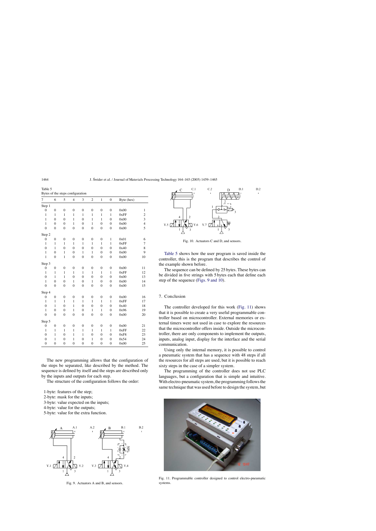
The new programming allows that the configuration of
the steps be separated, like described by the method. The
sequence is defined by itself and the steps are described only
by the inputs and outputs for each step.
The structure of the configuration follows the order:
1-byte: features of the step;
2-byte: mask for the inputs;
3-byte: value expected on the inputs;
4-byte: value for the outputs;
5-byte: value for the extra function.
Fig. 10. Actuators C and D, and sensors.
Table 5 shows how the user program is saved inside the
controller, this is the program that describes the control of
the example shown before.
The sequence can be defined by 25 bytes. These bytes can
be divided in five strings with 5 bytes each that define each
step of the sequence (Figs. 9 and 10).
7. Conclusion
The controller developed for this work (Fig. 11) shows
that it is possible to create a very useful programmable con-
troller based on microcontroller. External memories or ex-
ternal timers were not used in case to explore the resources
that the microcontroller offers inside. Outside the microcon-
troller, there are only components to implement the outputs,
inputs, analog input, display for the interface and the serial
communication.
Using only the internal memory, it is possible to control
a pneumatic system that has a sequence with 48 steps if all
the resources for all steps are used, but it is possible to reach
sixty steps in the case of a simpler system.
The programming of the controller does not use PLC
languages, but a configuration that is simple and intuitive.
With electro-pneumatic system, the programming follows the
same technique that was used before to design the system, but
Fig. 9. Actuators A and B, and sensors.
Fig. 11. Programmable controller designed to control electro-pneumatic
systems.
�
J. ´Swider et al. / Journal of Materials Processing Technology 164–165 (2005) 1459–1465
1465
here the designer works directly with the states or steps of
the system.
With a very simple machine language the designer can
define all the configuration of the step using four or five bytes.
It depends only on his experience to use all the resources of
the controller.
The controller task is not to work in the same way as a
commercial PLC but the purpose of it is to be an example
of a versatile controller that is designed for a specific area.
Because of that, it is not possible to say which one works
better; the system made with microcontroller is an alternative
that works in a simple way.
References
[1] E. Nelli Silva, Fluid-mechanics systems Manual, Escola Polit´ecnica-
USP, 2002 (in Portuguese).
[2] J. Swider, Control and Automation of Technological Process and
Mechatronic systems, Silesian University Publishing Company, Gli-
wice, 2002 (redaction, in Polish).
[3] J. Swider, G. Wszolek, W. Carvalho, Example of the system pre-
pared to be controlled by the controller based on microcontroller, in:
12 International Scientific Conference—Achievements in Mechanical
and Materials Engineering, Gliwice-Zakopane, Poland, 2003, pp. 965–
970.
[4] J. Swider, G. Wszolek, W. Carvalho, Controller based on microcon-
troller designed to execute the logic control of pneumatic systems,
in: 12 International Scientific Conference—Achievements in Mechan-
ical and Materials Engineering, Gliwice-Zakopane, Poland, 2003, pp.
959–964.
tasks of technological process control,
[5] J. Swider, G. Wszołek, The methodical collection of laboratory and
project
in: Pneumatic and
Electro-pneumatic Systems with Logical PLC Control, Silesian Uni-
versity Publishing Company, Gliwice, 2003.
[6] PIC 16f87x Datasheet. MICROCHIP, 2001.
[7] Application notes AN587 and AN546. MICROCHIP, 1997.
[8] Fundamental of electro-pneumatic—FESTO Didactic, 2000.
�


 2023年江西萍乡中考道德与法治真题及答案.doc
 2012年重庆南川中考生物真题及答案.doc
 2013年江西师范大学地理学综合及文艺理论基础考研真题.doc
 2020年四川甘孜小升初语文真题及答案I卷.doc
 2020年注册岩土工程师专业基础考试真题及答案.doc
 2023-2024学年福建省厦门市九年级上学期数学月考试题及答案.doc
 2021-2022学年辽宁省沈阳市大东区九年级上学期语文期末试题及答案.doc
 2022-2023学年北京东城区初三第一学期物理期末试卷及答案.doc
 2018上半年江西教师资格初中地理学科知识与教学能力真题及答案.doc
 2012年河北国家公务员申论考试真题及答案-省级.doc
 2020-2021学年江苏省扬州市江都区邵樊片九年级上学期数学第一次质量检测试题及答案.doc
 2022下半年黑龙江教师资格证中学综合素质真题及答案.doc