logo资料库

TC358746详细手册.pdf

第1页 / 共120页
第2页 / 共120页
第3页 / 共120页
第4页 / 共120页
第5页 / 共120页
第6页 / 共120页
第7页 / 共120页
第8页 / 共120页
资料共120页,剩余部分请下载后查看
1 Overview
2 Features
2.1 Typical Power Consumption
3 External Pins
3.1 TC358746 pinout desctription
3.2 TC358746AXBG BGA72 pin Count Summary
3.3 TC358748 pinout description
3.4 TC358748 BGA80 Pin Count Summary
3.5 TC358746 Pin Layout
3.6 TC358748 Pin Layout
3.7 System Overview
3.7.1 CSI-2 RX to Parallel Port Operation
3.7.2 Parallel Port to CSI-2 TX Operation
4 Function of MajorBlocks
4.1 CSI-2 TX/RX Protocol
4.2 CSI-2 RX Interface Block
4.3 CSI-2 TX Interface Block
4.4 CSI-2 Packet Format
4.5 Checksum Generation
4.6 CSI-2 TX One Frame Operation
4.6.1 4.6.1 Enable and Disable Parallel Input (Video)
4.7 Video Buffer Controller
4.8 Parallel Output mode
4.8.1 Overview
4.8.2 24-bit Un-Packed Data Format
4.8.3 Timing Diagrams for Video signals (Vsync and Hsync)
4.9 Parallel Input mode
4.9.1 Overview
4.9.2 Timing Diagrams for Video signals (Vsync and Hsync)
4.10 I2C
4.10.1 Overview
4.10.2 I2C Write Access
4.10.3 I2C Read Access
4.11 SPI Slave Interface
4.11.1 Clocking Modes
4.11.1.1 Timing Diagram
4.11.1.2 Providing Register Address over SPI Interface
4.11.1.3 SPI Write Access Translation
4.11.1.4 SPI Read Access Translation
4.11.2 Full Duplex
4.11.2.1 Back-2-back writes
4.11.2.2 Back-2-back reads
4.11.2.3 Write-after-Read
4.11.2.4 Read-after-Write
4.11.2.5 NOP-after-Read
5 Clock and System
5.1 CG Block diagram
5.2 Example of PLL Generated Clock Frequency
5.3 Output Clocks Generation
5.4 TC358746AXBG/TC358748XBG Power Up Procedure
5.5 TC358746AXBG/TC358748XBG Power Down Procedure
6 RegFile Block (Reg)
6.1 Register Map
6.2 Global Registers
6.2.1 Chip and Revision ID (ChipID: 0x0000)
6.2.1 System Control Register (SysCtl: 0x0002)
6.2.2 Configuration Control Register (ConfCtl: 0x0004)
6.2.3 FiFo Control Register (FiFoCtl: 0x0006)
6.2.4 Data Format Control Register (DataFmt: 0x0008)
6.2.5 MCLK Control Register (MclkCtl: 0x000C)
6.2.6 GPIO Enable
6.2.7 Register (GPIOEn: 0x000E)
6.2.8 GPIO Direction Register (GPIODir: 0x0010)
6.2.9 GPIO Pin Value Register (GPIOPin: 0x0012)
6.2.10 GPIO Output Value Register (GPIOOut: 0x0014)
6.2.11 PLL Control Register 0 (PLLCtl0: 0x0016)
6.2.12 PLL Control Register 1 (PLLCtl1: 0x0018)
6.2.13 CLK Control Register (ClkCtl: 0x0020)
6.2.14 Word Count Register (WordCnt: 0x0022)
6.2.15 Parallel In Miscellaneous Register (PP_MISC)
6.2.16 User Data Type Register (CSITX_DT: 0x0050)
6.3 Rx Control Registers
6.3.1 MIPI PHYClock Lane Control Register (PHYClkCtl: 0x0056)
6.3.2 MIPI PHY Data Lane 0 Control Register (PHYData0Ctl: 0x0058)
6.3.3 MIPI PHY Data Lane 1 Control Register (PHYData1Ctl: 0x005A)
6.3.4 MIPI PHY Data Lane 2 Control Register (PHYData2Ctl: 0x005C)
6.3.5 MIPI PHY Data Lane 3 Control Register (PHYData3Ctl: 0x005E)
6.3.6 MIPI PHY Time Delay Register (PHYTimDly: 0x0060)
6.3.7 MIPI PHY Status Register (PHYSta: 0x0062)
6.3.8 CSI-2 Error Status Register (CSIStatus: 0x0064)
6.3.9 CSI-2 Error Enable Register (CSIErrEn: 0x0066)
6.3.10 CSI-2 Multi-Data Lane SyncByte Error Register (MDLSynErr: 0x0068)
6.3.11 CSI-2 Data Type ID Register (CSIDID: 0x006A)
6.3.12 CSI-2Data Type ID Error Register (CSIDIDErr: 0x006C)
6.3.13 CSI-2 Data Length Register (CSIPktLen: 0x006E)
6.3.14 CSI-2 DPhy Control Register (CSIRX_DPCtl: 0x0070)
6.4 Rx StatusRegisters
6.4.1 Frame Error Counter (FrmErrCnt: 0x0080)
6.4.2 CRC Error Counter (CRCErrCnt: 0x0082)
6.4.3 Recoverable Packet Header Error Counter (CorErrCnt: 0x0084)
6.4.4 Un-recoverable Packet Header Error Counter (HdrErrCnt: 0x0086)
6.4.5 Un-supported Packet ID Error Counter (EIDErrCnt: 0x0088)
6.4.6 ControlError Counter (CtlErrCnt: 0x008A)
6.4.7 Recoverable SyncByte Error Counter (SoTErrCnt: 0x008C)
6.4.8 Un-recoverable SyncByte Error Counter (SynErrCnt: 0x008E)
6.4.9 Multi-Data Lane SyncByte Error Counter (MDLErrCnt: 0x0090)
6.4.10 FIFO Status Register(FIFOSTATUS: 0x00F8)
6.5 Tx D-PHY Registers
6.5.1 Clock Lane DPHY TX Control register (CLW_DPHYCONTTX: 0x0100)
6.5.2 Data Lane 0 DPHY TX Control register (D0W_DPHYCONTTX:0x0104)
6.5.3 Data Lane 1 DPHY TX Control Register (D1W_DPHYCONTTX: 0x0108)
6.5.4 Data Lane 2 DPHY TX Control Register (D2W_DPHYCONTTX: 0x010C)
6.5.5 Data Lane 3 DPHY TX Control Register (D3W_DPHYCONTTX: 0x0110)
6.5.6 Clock Lane DPHY Control Register (CLW_CNTRL: 0x0140)
6.5.7 Data Lane 0 DPHY Control Register (D0W_CNTRL: 0x0144)
6.5.8 Data Lane 1 DPHY Control Register (D1W_CNTRL: 0x0148)
6.5.9 Data Lane 2 DPHY Control Register (D2W_CNTRL: 0x014C)
6.5.10 Data Lane 3 DPHY Control Register (D3W_CNTRL: 0x0150)
6.6 Tx PPI Registers
6.6.1 PPI STARTCNTRL (STARTCNTRL: 0x0204)
6.6.2 PPI STATUS (PPISTATUS: 0x0208)
6.6.3 LINEINITCNT (LINEINITCNT: 0x0210)
6.6.4 LPTXTIMECNT (LPTXTIMECNT: 0x0214)
6.6.5 TCLK_HEADERCNT (TCLK_HEADERCNT: 0x0218)
6.6.6 TCLK_TRAILCNT (TCLK_TRAILCNT: 0x021C)
6.6.7 THS_HEADERCNT (THS_HEADERCNT: 0x0220)
6.6.8 TWAKEUP (TWAKEUP: 0x0224)
6.6.9 TCLK_POSTCNT (TCLK_POSTCNT: 0x0228)
6.6.10 THS_TRAILCNT (THS_TRAILCNT: 0x022C)
6.6.11 HSTXVREGCNT (HSTXVREGCNT: 0x0230)
6.6.12 HSTXVREGEN (HSTXVREGEN: 0x0234)
6.6.13 TXOPTIONCNTRL (TXOPTIONCNTRL: 0x0238)
6.7 Tx Control Register
6.7.1 CSI Configuration Read Register(CSI_CONTROL: 0x040C)
6.7.2 CSI STATUS Register (CSI_STATUS: 0x0410)
6.7.3 CSI_INT Register (CSI_INT: 0x0414)
6.7.4 CSI_INT_ENA Register (CSI_INT_ENA: 0x0418)
6.7.5 CSI_ERR Register (CSI_ERR: 0x044C)
6.7.6 CSI_ERR_INTENA (CSI_ERR_INTENA: 0x0450)
6.7.7 CSI_ERR_HALT Register(CSI_ERR_HALT: 0x0454)
6.7.8 CSI Configuration Register (CSI_CONFW: 0x0500)
6.7.9 CSI LP Command (CSI_LPCMD: 0x0500)
6.7.10 CSI_RESET Register (CSI_RESET: 0x0504)
6.7.11 CSI_INT_CLR Register(CSI_INT_CLR: 0x050C)
6.7.12 CSI_START (CSI_START: 0x0518)
6.8 TxDebug Register
6.8.1 Debug Active Line Count Register (DBG_LCNT: 0x00E0)
6.8.2 Debug Line Width Register (DBG_Width: 0x00E2)
6.8.3 Debug Vertical Blank Line Count Register (DBG_VBlank: 0x00E4)
6.8.4 Debug Video Data Register (DBG_Data: 0x00E8)
7 Package
7.1 TC358746A Package
7.2 TC358748 Package
8 Electrical Characteristics
8.1 Absolute Maximum Ratings
8.2 Recommended Operating Condition
8.3 DC Electrical Specification
9 Timing Definitions
9.1 MIPI CSI – 2 Timings
9.2 I2C Timings
9.3 Parallel Port Output Timings
9.4 Parallel Port Input Timings
9.5 SPI Input/Output Timings
RESTRICTIONS ON PRODUCT USE
TC358746AXBG/748XBG Functional Specification Rev 0.6 TC358746AXBG/TC358748XBG Functional Specification TOSHIBA TC358746A/746XBG Functional Spec Confidential Page 1 of 120 All rights reserved. This material is reprinted with the permission of the MIPI Alliance, Inc. No part(s) of this document may be disclosed, reproduced or used for any purpose other than as needed to support the use of the products of Toshiba Cooperation and its affiliates Copyright © 2005-2010 MIPI Alliance, Inc. All rights reserved. MIPI Alliance Member Confidential.
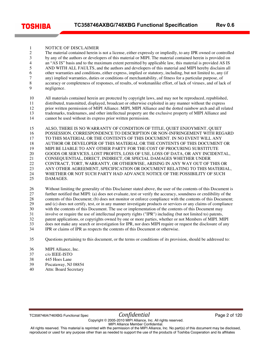
1 2 3 4 5 6 7 8 9 10 11 12 13 14 15 16 17 18 19 20 21 22 23 24 25 26 27 28 29 30 31 32 33 34 35 36 37 38 39 40 TC358746AXBG/748XBG Functional Specification Rev 0.6 NOTICE OF DISCLAIMER The material contained herein is not a license, either expressly or impliedly, to any IPR owned or controlled by any of the authors or developers of this material or MIPI. The material contained herein is provided on an “AS IS” basis and to the maximum extent permitted by applicable law, this material is provided AS IS AND WITH ALL FAULTS, and the authors and developers of this material and MIPI hereby disclaim all other warranties and conditions, either express, implied or statutory, including, but not limited to, any (if any) implied warranties, duties or conditions of merchantability, of fitness for a particular purpose, of accuracy or completeness of responses, of results, of workmanlike effort, of lack of viruses, and of lack of negligence. All materials contained herein are protected by copyright laws, and may not be reproduced, republished, distributed, transmitted, displayed, broadcast or otherwise exploited in any manner without the express prior written permission of MIPI Alliance. MIPI, MIPI Alliance and the dotted rainbow arch and all related trademarks, tradenames, and other intellectual property are the exclusive property of MIPI Alliance and cannot be used without its express prior written permission. ALSO, THERE IS NO WARRANTY OF CONDITION OF TITLE, QUIET ENJOYMENT, QUIET POSSESSION, CORRESPONDENCE TO DESCRIPTION OR NON-INFRINGEMENT WITH REGARD TO THIS MATERIAL OR THE CONTENTS OF THIS DOCUMENT. IN NO EVENT WILL ANY AUTHOR OR DEVELOPER OF THIS MATERIAL OR THE CONTENTS OF THIS DOCUMENT OR MIPI BE LIABLE TO ANY OTHER PARTY FOR THE COST OF PROCURING SUBSTITUTE GOODS OR SERVICES, LOST PROFITS, LOSS OF USE, LOSS OF DATA, OR ANY INCIDENTAL, CONSEQUENTIAL, DIRECT, INDIRECT, OR SPECIAL DAMAGES WHETHER UNDER CONTRACT, TORT, WARRANTY, OR OTHERWISE, ARISING IN ANY WAY OUT OF THIS OR ANY OTHER AGREEMENT, SPECIFICATION OR DOCUMENT RELATING TO THIS MATERIAL, WHETHER OR NOT SUCH PARTY HAD ADVANCE NOTICE OF THE POSSIBILITY OF SUCH DAMAGES. Without limiting the generality of this Disclaimer stated above, the user of the contents of this Document is further notified that MIPI: (a) does not evaluate, test or verify the accuracy, soundness or credibility of the contents of this Document; (b) does not monitor or enforce compliance with the contents of this Document; and (c) does not certify, test, or in any manner investigate products or services or any claims of compliance with the contents of this Document. The use or implementation of the contents of this Document may involve or require the use of intellectual property rights ("IPR") including (but not limited to) patents, patent applications, or copyrights owned by one or more parties, whether or not Members of MIPI. MIPI does not make any search or investigation for IPR, nor does MIPI require or request the disclosure of any IPR or claims of IPR as respects the contents of this Document or otherwise. Questions pertaining to this document, or the terms or conditions of its provision, should be addressed to: MIPI Alliance, Inc. c/o IEEE-ISTO 445 Hoes Lane Piscataway, NJ 08854 Attn: Board Secretary TC358746A/746XBG Functional Spec Confidential Page 2 of 120 All rights reserved. This material is reprinted with the permission of the MIPI Alliance, Inc. No part(s) of this document may be disclosed, reproduced or used for any purpose other than as needed to support the use of the products of Toshiba Cooperation and its affiliates Copyright © 2005-2010 MIPI Alliance, Inc. All rights reserved. MIPI Alliance Member Confidential.
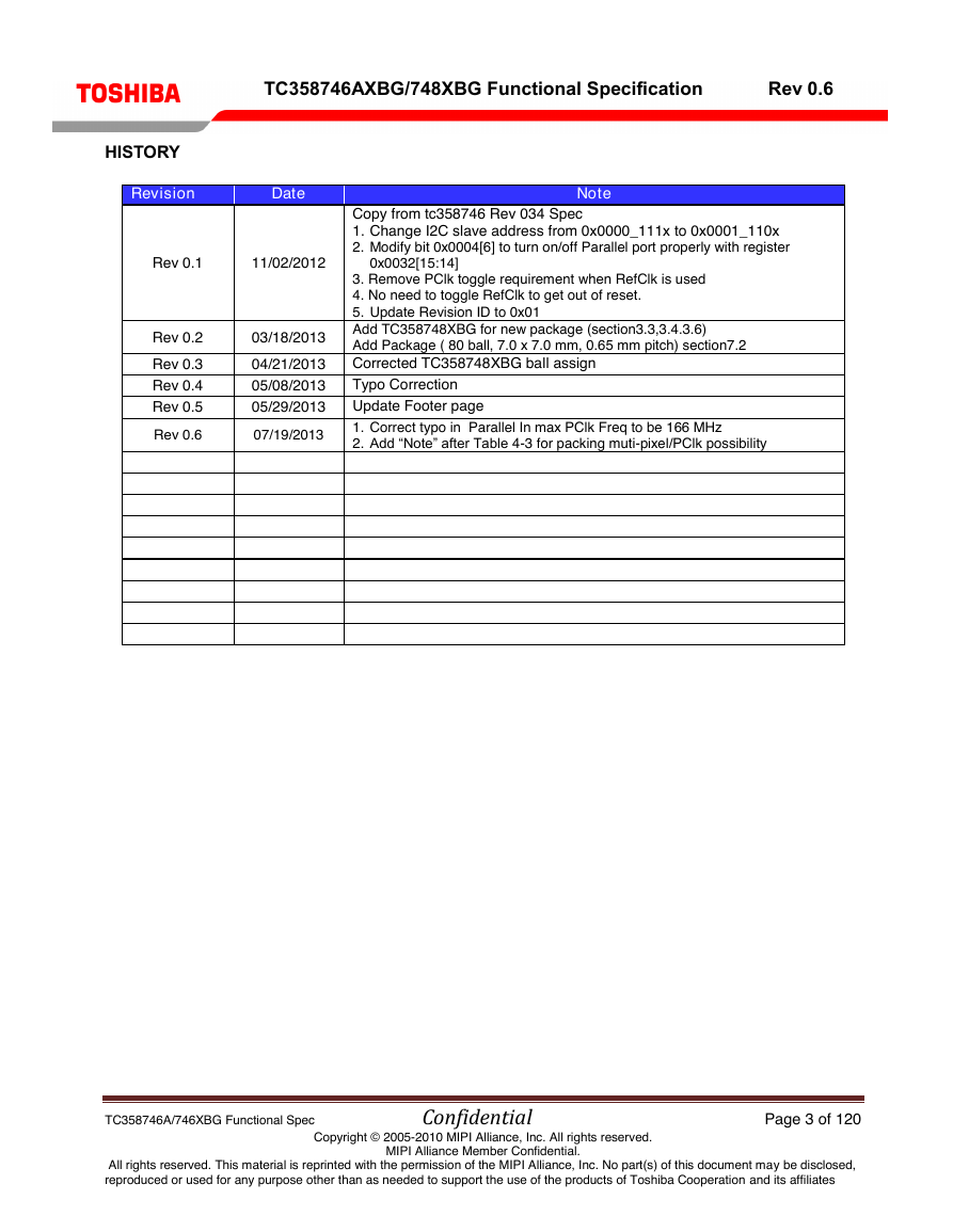
TC358746AXBG/748XBG Functional Specification Rev 0.6 HISTORY Revision Date Note Rev 0.1 11/02/2012 0x0032[15:14] Copy from tc358746 Rev 034 Spec 1. Change I2C slave address from 0x0000_111x to 0x0001_110x 2. Modify bit 0x0004[6] to turn on/off Parallel port properly with register Rev 0.2 03/18/2013 Rev 0.3 Rev 0.4 Rev 0.5 04/21/2013 05/08/2013 05/29/2013 Rev 0.6 07/19/2013 3. Remove PClk toggle requirement when RefClk is used 4. No need to toggle RefClk to get out of reset. 5. Update Revision ID to 0x01 Add TC358748XBG for new package (section3.3,3.4.3.6) Add Package ( 80 ball, 7.0 x 7.0 mm, 0.65 mm pitch) section7.2 Corrected TC358748XBG ball assign Typo Correction Update Footer page 1. Correct typo in Parallel In max PClk Freq to be 166 MHz 2. Add “Note” after Table 4-3 for packing muti-pixel/PClk possibility TC358746A/746XBG Functional Spec Confidential Page 3 of 120 All rights reserved. This material is reprinted with the permission of the MIPI Alliance, Inc. No part(s) of this document may be disclosed, reproduced or used for any purpose other than as needed to support the use of the products of Toshiba Cooperation and its affiliates Copyright © 2005-2010 MIPI Alliance, Inc. All rights reserved. MIPI Alliance Member Confidential.
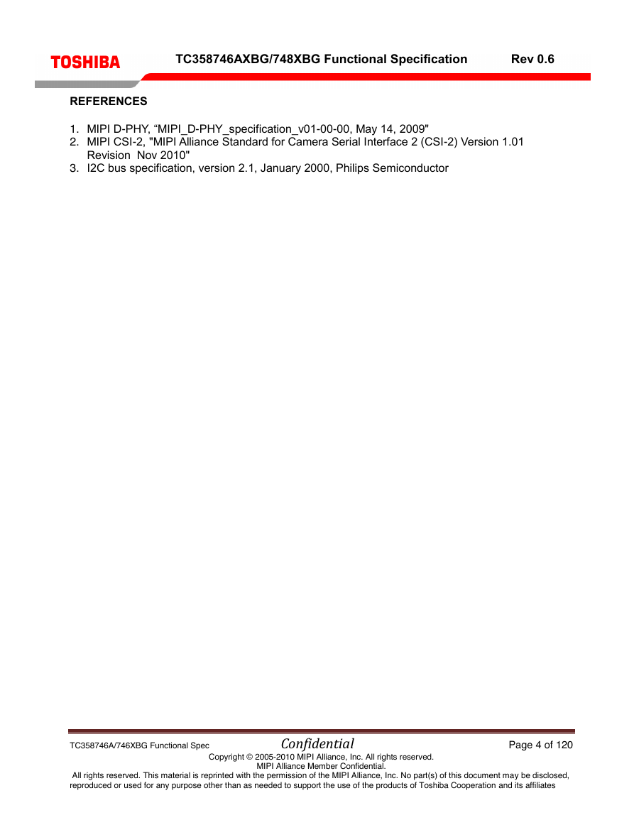
TC358746AXBG/748XBG Functional Specification REFERENCES 1. MIPI D-PHY, “MIPI_D-PHY_specification_v01-00-00, May 14, 2009" 2. MIPI CSI-2, "MIPI Alliance Standard for Camera Serial Interface 2 (CSI-2) Version 1.01 Rev 0.6 Revision Nov 2010" 3. I2C bus specification, version 2.1, January 2000, Philips Semiconductor TC358746A/746XBG Functional Spec Confidential Page 4 of 120 All rights reserved. This material is reprinted with the permission of the MIPI Alliance, Inc. No part(s) of this document may be disclosed, reproduced or used for any purpose other than as needed to support the use of the products of Toshiba Cooperation and its affiliates Copyright © 2005-2010 MIPI Alliance, Inc. All rights reserved. MIPI Alliance Member Confidential.
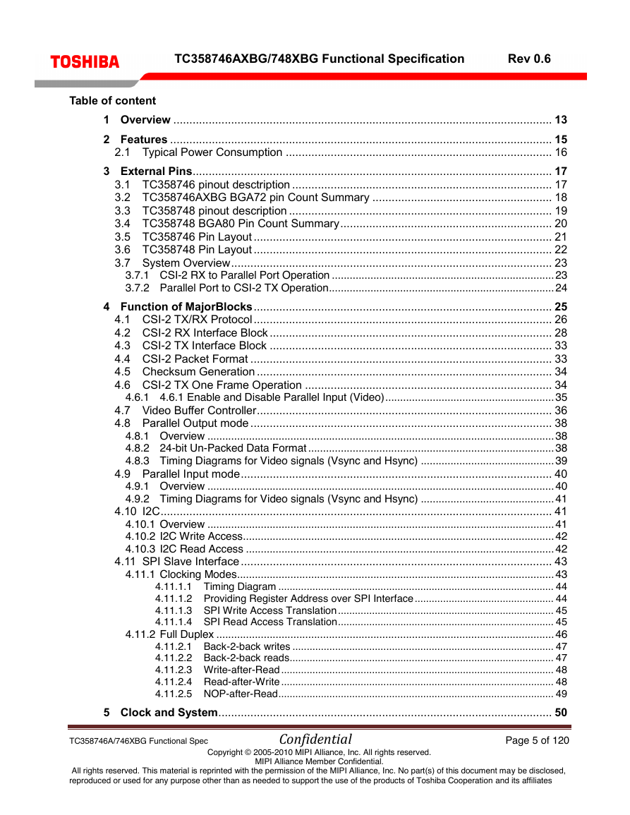
TC358746AXBG/748XBG Functional Specification Rev 0.6 Table of content 1 Overview ...................................................................................................................... 13 2 Features ....................................................................................................................... 15 2.1 Typical Power Consumption ................................................................................... 16 3 External Pins ................................................................................................................ 17 3.1 TC358746 pinout desctription ................................................................................. 17 3.2 TC358746AXBG BGA72 pin Count Summary ........................................................ 18 3.3 TC358748 pinout description .................................................................................. 19 3.4 TC358748 BGA80 Pin Count Summary .................................................................. 20 3.5 TC358746 Pin Layout ............................................................................................. 21 3.6 TC358748 Pin Layout ............................................................................................. 22 3.7 System Overview .................................................................................................... 23 3.7.1 CSI-2 RX to Parallel Port Operation ........................................................................... 23 3.7.2 Parallel Port to CSI-2 TX Operation ............................................................................ 24 4 Function of MajorBlocks ............................................................................................. 25 4.1 CSI-2 TX/RX Protocol ............................................................................................. 26 4.2 CSI-2 RX Interface Block ........................................................................................ 28 4.3 CSI-2 TX Interface Block ........................................................................................ 33 4.4 CSI-2 Packet Format .............................................................................................. 33 4.5 Checksum Generation ............................................................................................ 34 4.6 CSI-2 TX One Frame Operation ............................................................................. 34 4.6.1 4.6.1 Enable and Disable Parallel Input (Video) ......................................................... 35 4.7 Video Buffer Controller ............................................................................................ 36 4.8 Parallel Output mode .............................................................................................. 38 4.8.1 Overview ..................................................................................................................... 38 4.8.2 24-bit Un-Packed Data Format ................................................................................... 38 4.8.3 Timing Diagrams for Video signals (Vsync and Hsync) ............................................. 39 4.9 Parallel Input mode ................................................................................................. 40 4.9.1 Overview ..................................................................................................................... 40 4.9.2 Timing Diagrams for Video signals (Vsync and Hsync) ............................................. 41 4.10 I2C .......................................................................................................................... 41 4.10.1 Overview ..................................................................................................................... 41 4.10.2 I2C Write Access ......................................................................................................... 42 4.10.3 I2C Read Access ........................................................................................................ 42 4.11 SPI Slave Interface ................................................................................................. 43 4.11.1 Clocking Modes ........................................................................................................... 43 4.11.1.1 Timing Diagram ................................................................................................. 44 4.11.1.2 Providing Register Address over SPI Interface ................................................. 44 4.11.1.3 SPI Write Access Translation ............................................................................ 45 4.11.1.4 SPI Read Access Translation ............................................................................ 45 4.11.2 Full Duplex .................................................................................................................. 46 4.11.2.1 Back-2-back writes ............................................................................................ 47 4.11.2.2 Back-2-back reads ............................................................................................. 47 4.11.2.3 Write-after-Read ................................................................................................ 48 4.11.2.4 Read-after-Write ................................................................................................ 48 4.11.2.5 NOP-after-Read ................................................................................................. 49 5 Clock and System ........................................................................................................ 50 TC358746A/746XBG Functional Spec Confidential Page 5 of 120 All rights reserved. This material is reprinted with the permission of the MIPI Alliance, Inc. No part(s) of this document may be disclosed, reproduced or used for any purpose other than as needed to support the use of the products of Toshiba Cooperation and its affiliates Copyright © 2005-2010 MIPI Alliance, Inc. All rights reserved. MIPI Alliance Member Confidential.
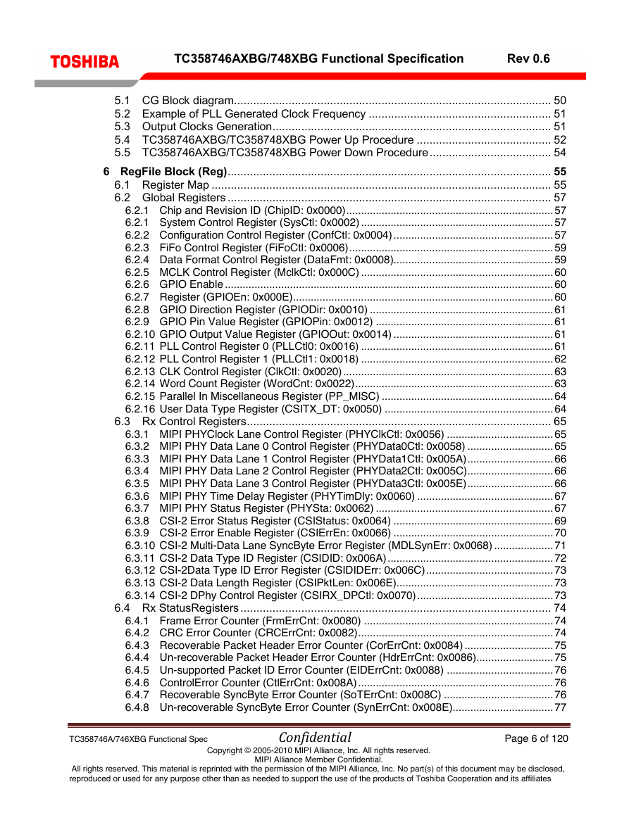
TC358746AXBG/748XBG Functional Specification Rev 0.6 5.1 CG Block diagram ................................................................................................... 50 5.2 Example of PLL Generated Clock Frequency ......................................................... 51 5.3 Output Clocks Generation ....................................................................................... 51 5.4 TC358746AXBG/TC358748XBG Power Up Procedure .......................................... 52 5.5 TC358746AXBG/TC358748XBG Power Down Procedure ...................................... 54 6 RegFile Block (Reg) ..................................................................................................... 55 6.1 Register Map .......................................................................................................... 55 6.2 Global Registers ..................................................................................................... 57 6.2.1 Chip and Revision ID (ChipID: 0x0000) ...................................................................... 57 6.2.1 System Control Register (SysCtl: 0x0002) ................................................................. 57 6.2.2 Configuration Control Register (ConfCtl: 0x0004) ...................................................... 57 6.2.3 FiFo Control Register (FiFoCtl: 0x0006) ..................................................................... 59 6.2.4 Data Format Control Register (DataFmt: 0x0008)...................................................... 59 6.2.5 MCLK Control Register (MclkCtl: 0x000C) ................................................................. 60 6.2.6 GPIO Enable ............................................................................................................... 60 6.2.7 Register (GPIOEn: 0x000E) ........................................................................................ 60 6.2.8 GPIO Direction Register (GPIODir: 0x0010) .............................................................. 61 6.2.9 GPIO Pin Value Register (GPIOPin: 0x0012) ............................................................ 61 6.2.10 GPIO Output Value Register (GPIOOut: 0x0014) ...................................................... 61 6.2.11 PLL Control Register 0 (PLLCtl0: 0x0016) ................................................................. 61 6.2.12 PLL Control Register 1 (PLLCtl1: 0x0018) ................................................................. 62 6.2.13 CLK Control Register (ClkCtl: 0x0020) ....................................................................... 63 6.2.14 Word Count Register (WordCnt: 0x0022) ................................................................... 63 6.2.15 Parallel In Miscellaneous Register (PP_MISC) .......................................................... 64 6.2.16 User Data Type Register (CSITX_DT: 0x0050) ......................................................... 64 6.3 Rx Control Registers ............................................................................................... 65 6.3.1 MIPI PHYClock Lane Control Register (PHYClkCtl: 0x0056) .................................... 65 6.3.2 MIPI PHY Data Lane 0 Control Register (PHYData0Ctl: 0x0058) ............................. 65 6.3.3 MIPI PHY Data Lane 1 Control Register (PHYData1Ctl: 0x005A) ............................. 66 6.3.4 MIPI PHY Data Lane 2 Control Register (PHYData2Ctl: 0x005C) ............................. 66 6.3.5 MIPI PHY Data Lane 3 Control Register (PHYData3Ctl: 0x005E) ............................. 66 6.3.6 MIPI PHY Time Delay Register (PHYTimDly: 0x0060) .............................................. 67 6.3.7 MIPI PHY Status Register (PHYSta: 0x0062) ............................................................ 67 6.3.8 CSI-2 Error Status Register (CSIStatus: 0x0064) ...................................................... 69 6.3.9 CSI-2 Error Enable Register (CSIErrEn: 0x0066) ...................................................... 70 6.3.10 CSI-2 Multi-Data Lane SyncByte Error Register (MDLSynErr: 0x0068) .................... 71 6.3.11 CSI-2 Data Type ID Register (CSIDID: 0x006A) ........................................................ 72 6.3.12 CSI-2Data Type ID Error Register (CSIDIDErr: 0x006C) ........................................... 73 6.3.13 CSI-2 Data Length Register (CSIPktLen: 0x006E)..................................................... 73 6.3.14 CSI-2 DPhy Control Register (CSIRX_DPCtl: 0x0070) .............................................. 73 6.4 Rx StatusRegisters ................................................................................................. 74 6.4.1 Frame Error Counter (FrmErrCnt: 0x0080) ................................................................ 74 6.4.2 CRC Error Counter (CRCErrCnt: 0x0082) .................................................................. 74 6.4.3 Recoverable Packet Header Error Counter (CorErrCnt: 0x0084) .............................. 75 6.4.4 Un-recoverable Packet Header Error Counter (HdrErrCnt: 0x0086).......................... 75 6.4.5 Un-supported Packet ID Error Counter (EIDErrCnt: 0x0088) .................................... 76 6.4.6 ControlError Counter (CtlErrCnt: 0x008A) .................................................................. 76 6.4.7 Recoverable SyncByte Error Counter (SoTErrCnt: 0x008C) ..................................... 76 6.4.8 Un-recoverable SyncByte Error Counter (SynErrCnt: 0x008E).................................. 77 TC358746A/746XBG Functional Spec Confidential Page 6 of 120 All rights reserved. This material is reprinted with the permission of the MIPI Alliance, Inc. No part(s) of this document may be disclosed, reproduced or used for any purpose other than as needed to support the use of the products of Toshiba Cooperation and its affiliates Copyright © 2005-2010 MIPI Alliance, Inc. All rights reserved. MIPI Alliance Member Confidential.
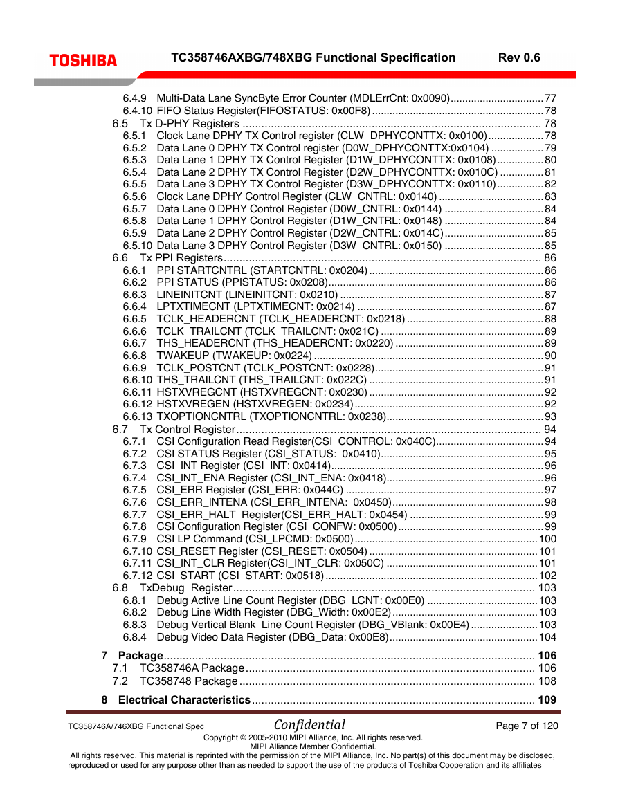
TC358746AXBG/748XBG Functional Specification Rev 0.6 6.4.9 Multi-Data Lane SyncByte Error Counter (MDLErrCnt: 0x0090) ................................ 77 6.4.10 FIFO Status Register(FIFOSTATUS: 0x00F8) ........................................................... 78 6.5 Tx D-PHY Registers ............................................................................................... 78 6.5.1 Clock Lane DPHY TX Control register (CLW_DPHYCONTTX: 0x0100) ................... 78 6.5.2 Data Lane 0 DPHY TX Control register (D0W_DPHYCONTTX:0x0104) .................. 79 6.5.3 Data Lane 1 DPHY TX Control Register (D1W_DPHYCONTTX: 0x0108) ................ 80 6.5.4 Data Lane 2 DPHY TX Control Register (D2W_DPHYCONTTX: 0x010C) ............... 81 6.5.5 Data Lane 3 DPHY TX Control Register (D3W_DPHYCONTTX: 0x0110) ................ 82 6.5.6 Clock Lane DPHY Control Register (CLW_CNTRL: 0x0140) .................................... 83 6.5.7 Data Lane 0 DPHY Control Register (D0W_CNTRL: 0x0144) .................................. 84 6.5.8 Data Lane 1 DPHY Control Register (D1W_CNTRL: 0x0148) .................................. 84 6.5.9 Data Lane 2 DPHY Control Register (D2W_CNTRL: 0x014C) .................................. 85 6.5.10 Data Lane 3 DPHY Control Register (D3W_CNTRL: 0x0150) .................................. 85 6.6 Tx PPI Registers ..................................................................................................... 86 6.6.1 PPI STARTCNTRL (STARTCNTRL: 0x0204) ............................................................ 86 6.6.2 PPI STATUS (PPISTATUS: 0x0208) .......................................................................... 86 6.6.3 LINEINITCNT (LINEINITCNT: 0x0210) ...................................................................... 87 6.6.4 LPTXTIMECNT (LPTXTIMECNT: 0x0214) ................................................................ 87 6.6.5 TCLK_HEADERCNT (TCLK_HEADERCNT: 0x0218) ............................................... 88 6.6.6 TCLK_TRAILCNT (TCLK_TRAILCNT: 0x021C) ........................................................ 89 6.6.7 THS_HEADERCNT (THS_HEADERCNT: 0x0220) ................................................... 89 6.6.8 TWAKEUP (TWAKEUP: 0x0224) ............................................................................... 90 6.6.9 TCLK_POSTCNT (TCLK_POSTCNT: 0x0228) .......................................................... 91 6.6.10 THS_TRAILCNT (THS_TRAILCNT: 0x022C) ............................................................ 91 6.6.11 HSTXVREGCNT (HSTXVREGCNT: 0x0230) ............................................................ 92 6.6.12 HSTXVREGEN (HSTXVREGEN: 0x0234) ................................................................. 92 6.6.13 TXOPTIONCNTRL (TXOPTIONCNTRL: 0x0238) ...................................................... 93 6.7 Tx Control Register ................................................................................................. 94 6.7.1 CSI Configuration Read Register(CSI_CONTROL: 0x040C)..................................... 94 6.7.2 CSI STATUS Register (CSI_STATUS: 0x0410) ........................................................ 95 6.7.3 CSI_INT Register (CSI_INT: 0x0414) ......................................................................... 96 6.7.4 CSI_INT_ENA Register (CSI_INT_ENA: 0x0418)...................................................... 96 6.7.5 CSI_ERR Register (CSI_ERR: 0x044C) .................................................................... 97 6.7.6 CSI_ERR_INTENA (CSI_ERR_INTENA: 0x0450) .................................................... 98 6.7.7 CSI_ERR_HALT Register(CSI_ERR_HALT: 0x0454) .............................................. 99 6.7.8 CSI Configuration Register (CSI_CONFW: 0x0500) .................................................. 99 6.7.9 CSI LP Command (CSI_LPCMD: 0x0500) ............................................................... 100 6.7.10 CSI_RESET Register (CSI_RESET: 0x0504) .......................................................... 101 6.7.11 CSI_INT_CLR Register(CSI_INT_CLR: 0x050C) .................................................... 101 6.7.12 CSI_START (CSI_START: 0x0518) ......................................................................... 102 6.8 TxDebug Register ................................................................................................ 103 6.8.1 Debug Active Line Count Register (DBG_LCNT: 0x00E0) ...................................... 103 6.8.2 Debug Line Width Register (DBG_Width: 0x00E2) .................................................. 103 6.8.3 Debug Vertical Blank Line Count Register (DBG_VBlank: 0x00E4) ....................... 103 6.8.4 Debug Video Data Register (DBG_Data: 0x00E8) ................................................... 104 7 Package ...................................................................................................................... 106 7.1 TC358746A Package ............................................................................................ 106 7.2 TC358748 Package .............................................................................................. 108 8 Electrical Characteristics .......................................................................................... 109 TC358746A/746XBG Functional Spec Confidential Page 7 of 120 All rights reserved. This material is reprinted with the permission of the MIPI Alliance, Inc. No part(s) of this document may be disclosed, reproduced or used for any purpose other than as needed to support the use of the products of Toshiba Cooperation and its affiliates Copyright © 2005-2010 MIPI Alliance, Inc. All rights reserved. MIPI Alliance Member Confidential.
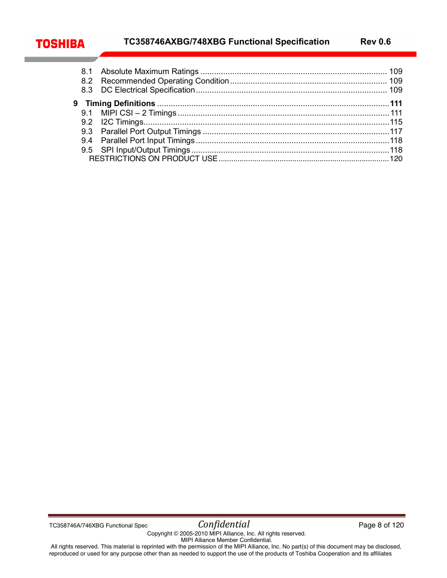
TC358746AXBG/748XBG Functional Specification Rev 0.6 8.1 Absolute Maximum Ratings .................................................................................. 109 8.2 Recommended Operating Condition ..................................................................... 109 8.3 DC Electrical Specification .................................................................................... 109 9 Timing Definitions ...................................................................................................... 111 9.1 MIPI CSI – 2 Timings ............................................................................................. 111 9.2 I2C Timings ............................................................................................................ 115 9.3 Parallel Port Output Timings .................................................................................. 117 9.4 Parallel Port Input Timings ..................................................................................... 118 9.5 SPI Input/Output Timings ....................................................................................... 118 RESTRICTIONS ON PRODUCT USE ................................................................................. 120 TC358746A/746XBG Functional Spec Confidential Page 8 of 120 All rights reserved. This material is reprinted with the permission of the MIPI Alliance, Inc. No part(s) of this document may be disclosed, reproduced or used for any purpose other than as needed to support the use of the products of Toshiba Cooperation and its affiliates Copyright © 2005-2010 MIPI Alliance, Inc. All rights reserved. MIPI Alliance Member Confidential.
分享到:
收藏