logo资料库

Keba相关资料.pdf

第1页 / 共140页
第2页 / 共140页
第3页 / 共140页
第4页 / 共140页
第5页 / 共140页
第6页 / 共140页
第7页 / 共140页
第8页 / 共140页
资料共140页,剩余部分请下载后查看
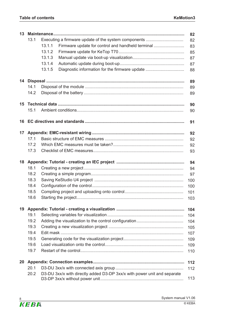
Table of contents
1 Introduction
1.1 Purpose of the document
1.2 Preconditions
1.3 Intended use
1.4 Notes on this document
1.4.1 Contents of the document
1.4.2 Not contained in this document
1.5 Further documentation
1.6 Relevant countries and registrations
2 Safety notes
2.1 Representation
2.2 General safety insutructions
2.3 Personnel safety
2.4 Safety instructions for projecting
3 System overview
3.1 Hardware architecture
3.2 Software architecture
3.3 Network design
3.4 Technical specification
3.5 KeControl - CPU modules
3.5.1 Extension modules
3.6 KeDrive - Drive technique
3.7 KeConnect - Bus link module
3.8 KeConnect peripheral devices
3.9 Buses
3.9.1 EtherCAT
3.9.2 sercos III
3.9.3 Profinet
3.9.4 EtherNet/IP
3.9.5 CAN
3.9.6 Ethernet
3.9.7 Modbus TCP/IP
3.10 KeView - Visualization components
3.10.1 Stationary operating devices
3.10.2 Mobile operating devices
3.10.3 Visualization system KeMotion3TeachView
3.10.4 Visualization systems
3.11 KeStudio tool suite
3.11.1 KeStudio
3.11.2 ViewEdit
3.11.3 DriveManager
3.11.4 CppEdit
3.11.5 KeStudio UosDiagnostic
3.11.6 KeStudio Scope
3.11.7 Robot programming with KAIROEdit
3.12 Libraries and interfaces
3.12.1 IEC standard libraries
3.12.2 KeStudio libraries
3.12.3 OPC UA interface
3.13 Robot macros instruction set
4 Assembly and removal
4.1 Space requirement
4.2 Air conditioning, ventilation
4.3 Use of air filters
5 Connections and wiring
5.1 Interfaces
5.1.1 CAN
5.1.2 RS-232-C
5.1.3 RS-485/422
5.1.4 Ethernet, Gigabit-Ethernet, EtherCAT, PROFINET
5.1.5 Graphic interface
5.1.6 USB
5.2 Inputs/outputs
5.2.1 Front panel connectors
5.2.2 Power supply
5.2.3 Digital inputs
5.2.4 Digital outputs
5.2.5 Analog input (current or voltage input)
5.2.6 Analog output (current or voltage output)
5.2.7 Transducer power supply and reference voltage
5.2.8 Input for thermo couples
5.2.9 Incremental encoder input
5.2.10 PWM output
5.3 Connecting the bus link module
5.4 Connecting the stationary operating panel
5.5 Connecting the Handterminal
5.6 Connecting axis modules
5.7 Test of interference immunity
6 Displays and operating elements
6.1 Button and display, general information
7 Operating behavior
7.1 Start-up
7.1.1 Display during start-up
8 Software installation
8.1 Install firmware of the control
8.2 Install simulation on the PC
9 Configuration
9.1 Data exchange between control and visualization
9.2 Device configuration via static operating device
9.2.1 Diagnosis Data
9.2.2 Display
9.2.3 Licenses
9.2.4 Network
9.2.5 Reboot
9.2.6 Version info
10 Device Administration (DevAdmin)
10.1 Tab "Diagnostics"
10.2 Tab "Configuration"
10.3 Tab "Backup/Restore"
10.4 Change password for DevAdmin
11 Program development
11.1 Task priorities
11.2 Fast control
11.3 Sample projects
12 Diagnosis
12.1 Control diagnosis
12.1.1 Error codes
12.2 Drive diagnosis
12.3 Diagnosis data for KEBA
12.3.1 Status report
12.3.2 Crashreport
12.3.3 Access to flash storage medium
13 Maintenance
13.1 Executing a firmware update of the system components
13.1.1 Firmware update for control and handheld terminal
13.1.2 Firmware update for KeTop T70
13.1.3 Manual update via boot-up visualization
13.1.4 Automatic update during boot-up
13.1.5 Diagnostic information for the firmware update
14 Disposal
14.1 Disposal of the module
14.2 Disposal of the battery
15 Technical data
15.1 Ambient conditions
16 EC directives and standards
17 Appendix: EMC-resistant wiring
17.1 Basic structure of EMC measures
17.2 Which EMC measures must be taken?
17.3 Checklist of EMC measures
18 Appendix: Tutorial - creating an IEC project
18.1 Creating a new project
18.2 Creating a simple program
18.3 Saving KeStudio U4 project
18.4 Configuration of the control
18.5 Compiling project and uploading onto control
18.6 Starting the project
19 Appendix: Tutorial - creating a visualization
19.1 Selecting variables for visualization
19.2 Adding the visualization to the control configuration
19.3 Creating a new visualization project
19.4 Edit mask
19.5 Generating code for the visualization project
19.6 Load visualization onto the control
19.7 Restart of the control
20 Appendix: Connection examples
20.1 D3-DU 3xx/x with connected axis group
20.2 D3-DU 3xx/x with directly added D3-DP 3xx/x with power unit and separate D3-DP 3xx/x without power unit
20.3 D3-DU 3xx/x with directly added D3-DP 3xx/x with power unit and separate D3-DP 3xx/x with power unit
20.4 D3-DU 3xx/x connected bus coupler module
21 Appendix: Asynchronous motors requirements
22 Appendix: Addressing in the Ethernet (basics)
23 Appendix: Tutorial - Start-up of a KeDrive D3 drive (EtherCAT)
23.1 Preconditions
23.1.1 Hardware components for EtherCAT
23.1.2 Software components
23.2 Wiring
23.3 Configuration with KeStudio
23.3.1 Create project
23.3.2 Drive configuration on the control
23.3.3 Configuration of the control
23.3.4 Compiling project and uploading onto control
23.4 Drive configuration
23.5 Drive diagnosis
23.5.1 Ethernet over EtherCAT (EoE)
24 Appendix: Tutorial - fast control
24.1 Preconditions and needed components
24.2 Task
24.3 Wiring
24.4 Creating example application
25 Appendix: Tutorial - call C function from IEC
25.1 Preconditions and needed components
25.2 Task
25.3 Creation of IEC function
25.4 Creating the C function and download
25.5 Calling the IEC funtion in the IEC application and download
26 Appendix: Terminology
Index
Kemro KeMotion3 Automation system System manual V 1.06 Translation of the original manual
Document: V 1.06 / Article No.: 1008566 Filename: KeMotion3_shben.pdf Pages: 140 © KEBA Specifications are subject to change due to further technical developments. Details presented may be subject to correction. All rights reserved. KEBA AG Headquarters: Gewerbepark Urfahr, 4041 Linz, Austria, Phone: +43 732 7090-0, Fax: +43 732 7309-10, keba@keba.com For information about our subsidiaries please look at www.keba.com.
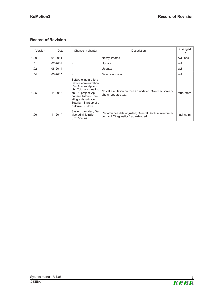
KeMotion3 Record of Revision Record of Revision Version Date Change in chapter Description Newly created Updated Updated Several updates 1.00 1.01 1.02 1.04 01-2013 07-2014 08-2014 05-2017 1.05 11-2017 1.06 11-2017 - - - - Software installation; Device administration (DevAdmin); Appen- dix: Tutorial - creating an IEC project; Ap- pendix: Tutorial - cre- ating a visualization; Tutorial - Start-up of a KeDrive D3 drive System overview; De- vice administration (DevAdmin) Changed by swb, hasl swb swb swb "Install simulation on the PC" updated; Switched screen- shots, Updated text raud, sthm Performance data adjusted; General DevAdmin informa- tion and "Diagnostics" tab extended hasl, sthm System manual V1.06 © KEBA 3
KeMotion3 4 System manual V1.06 © KEBA
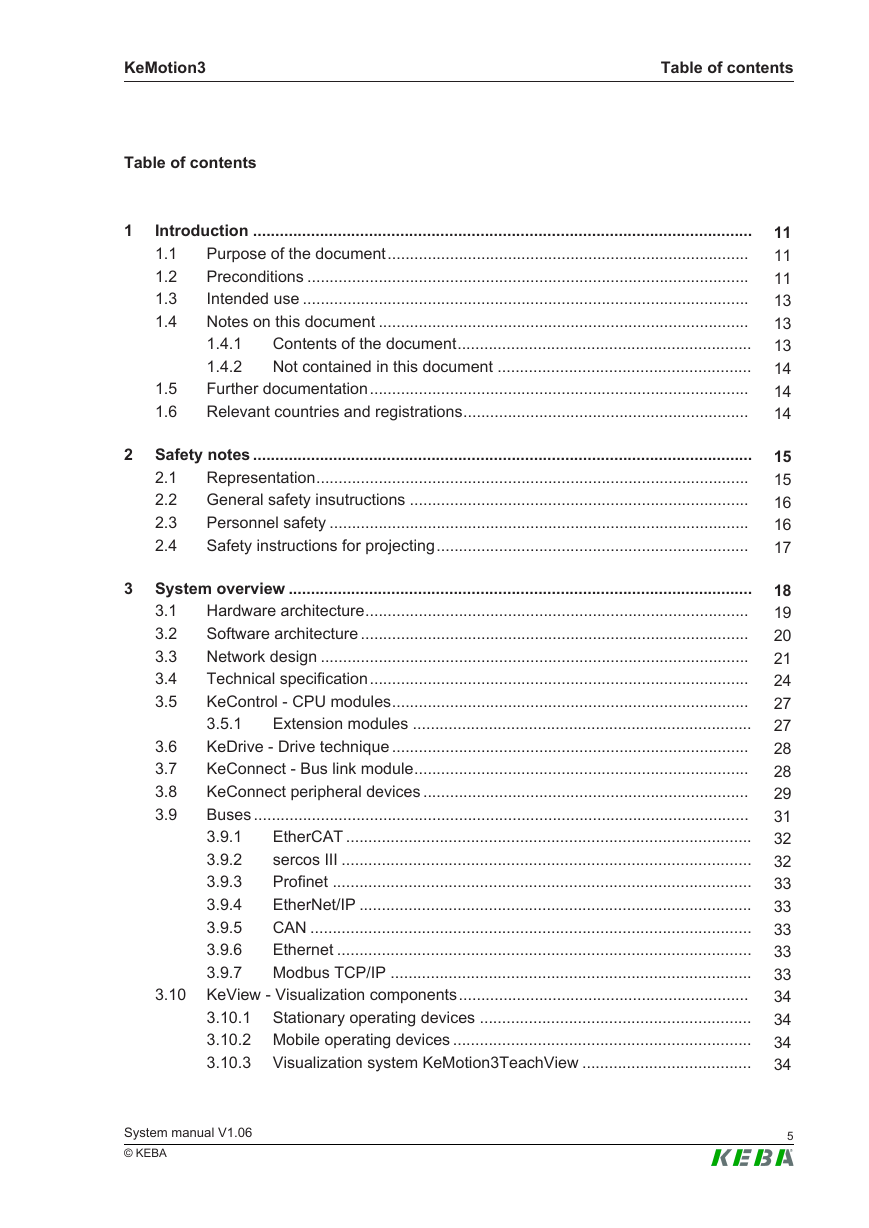
KeMotion3 Table of contents Table of contents 1 2 3 Introduction ................................................................................................................ 1.1 Purpose of the document................................................................................. Preconditions ................................................................................................... 1.2 Intended use .................................................................................................... 1.3 1.4 Notes on this document ................................................................................... Contents of the document.................................................................. 1.4.1 1.4.2 Not contained in this document ......................................................... Further documentation..................................................................................... Relevant countries and registrations................................................................ 1.5 1.6 Safety notes ................................................................................................................ 2.1 Representation................................................................................................. General safety insutructions ............................................................................ 2.2 Personnel safety .............................................................................................. 2.3 2.4 Safety instructions for projecting...................................................................... 3.6 3.7 3.8 3.9 System overview ........................................................................................................ Hardware architecture...................................................................................... 3.1 3.2 Software architecture ....................................................................................... Network design ................................................................................................ 3.3 Technical specification..................................................................................... 3.4 3.5 KeControl - CPU modules................................................................................ 3.5.1 Extension modules ............................................................................ KeDrive - Drive technique ................................................................................ KeConnect - Bus link module........................................................................... KeConnect peripheral devices ......................................................................... Buses ............................................................................................................... 3.9.1 EtherCAT ........................................................................................... sercos III ............................................................................................ 3.9.2 Profinet .............................................................................................. 3.9.3 3.9.4 EtherNet/IP ........................................................................................ CAN ................................................................................................... 3.9.5 Ethernet ............................................................................................. 3.9.6 3.9.7 Modbus TCP/IP ................................................................................. 3.10 KeView - Visualization components................................................................. 3.10.1 Stationary operating devices ............................................................. 3.10.2 Mobile operating devices ................................................................... 3.10.3 Visualization system KeMotion3TeachView ...................................... System manual V1.06 © KEBA 11 11 11 13 13 13 14 14 14 15 15 16 16 17 18 19 20 21 24 27 27 28 28 29 31 32 32 33 33 33 33 33 34 34 34 34 5
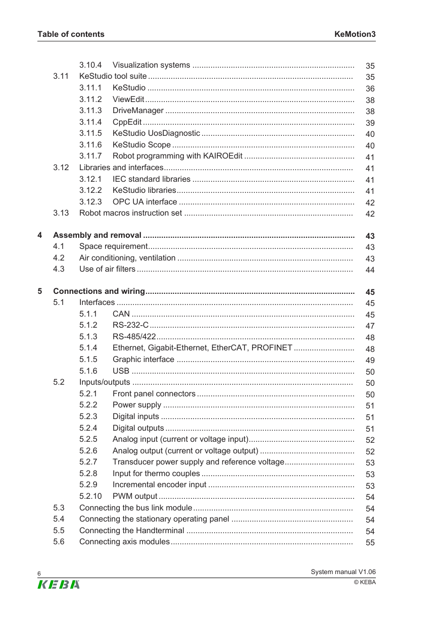
Table of contents KeMotion3 3.10.4 Visualization systems ........................................................................ 3.11 KeStudio tool suite ........................................................................................... 3.11.1 KeStudio ............................................................................................ 3.11.2 ViewEdit............................................................................................. 3.11.3 DriveManager .................................................................................... 3.11.4 CppEdit .............................................................................................. 3.11.5 KeStudio UosDiagnostic .................................................................... 3.11.6 KeStudio Scope ................................................................................. 3.11.7 Robot programming with KAIROEdit ................................................. Libraries and interfaces.................................................................................... IEC standard libraries ........................................................................ 3.12.1 3.12.2 KeStudio libraries............................................................................... 3.12.3 OPC UA interface .............................................................................. 3.13 Robot macros instruction set ........................................................................... 3.12 4 Assembly and removal .............................................................................................. Space requirement........................................................................................... Air conditioning, ventilation .............................................................................. Use of air filters ................................................................................................ 4.1 4.2 4.3 5.2 5.1 5 Connections and wiring............................................................................................. Interfaces ......................................................................................................... 5.1.1 CAN ................................................................................................... RS-232-C........................................................................................... 5.1.2 RS-485/422........................................................................................ 5.1.3 5.1.4 Ethernet, Gigabit-Ethernet, EtherCAT, PROFINET ........................... Graphic interface ............................................................................... 5.1.5 5.1.6 USB ................................................................................................... Inputs/outputs .................................................................................................. 5.2.1 Front panel connectors ...................................................................... Power supply ..................................................................................... 5.2.2 Digital inputs ...................................................................................... 5.2.3 5.2.4 Digital outputs .................................................................................... Analog input (current or voltage input)............................................... 5.2.5 Analog output (current or voltage output) .......................................... 5.2.6 5.2.7 Transducer power supply and reference voltage............................... Input for thermo couples .................................................................... 5.2.8 Incremental encoder input ................................................................. 5.2.9 5.2.10 PWM output ....................................................................................... Connecting the bus link module....................................................................... Connecting the stationary operating panel ...................................................... Connecting the Handterminal .......................................................................... Connecting axis modules................................................................................. 5.3 5.4 5.5 5.6 35 35 36 38 38 39 40 40 41 41 41 41 42 42 43 43 43 44 45 45 45 47 48 48 49 50 50 50 51 51 51 52 52 53 53 53 54 54 54 54 55 6 System manual V1.06 © KEBA
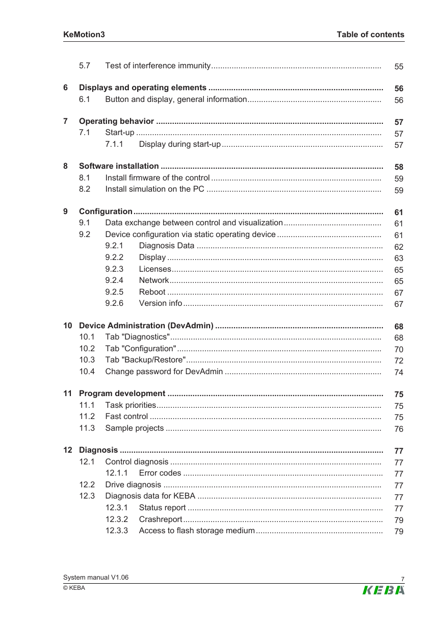
KeMotion3 Table of contents 5.7 Test of interference immunity........................................................................... 6 Displays and operating elements ............................................................................. Button and display, general information........................................................... 6.1 7 Operating behavior .................................................................................................... Start-up ............................................................................................................ Display during start-up....................................................................... 7.1.1 7.1 8 Software installation .................................................................................................. Install firmware of the control ........................................................................... 8.1 8.2 Install simulation on the PC ............................................................................. 9.1 9.2 9 Configuration.............................................................................................................. Data exchange between control and visualization........................................... Device configuration via static operating device .............................................. 9.2.1 Diagnosis Data .................................................................................. Display ............................................................................................... 9.2.2 Licenses............................................................................................. 9.2.3 9.2.4 Network.............................................................................................. Reboot ............................................................................................... 9.2.5 9.2.6 Version info........................................................................................ 10 Device Administration (DevAdmin) .......................................................................... 10.1 Tab "Diagnostics"............................................................................................. 10.2 Tab "Configuration".......................................................................................... 10.3 Tab "Backup/Restore"...................................................................................... 10.4 Change password for DevAdmin ..................................................................... 11 Program development ............................................................................................... Task priorities................................................................................................... 11.1 11.2 Fast control ...................................................................................................... 11.3 Sample projects ............................................................................................... 12.1.1 12 Diagnosis .................................................................................................................... 12.1 Control diagnosis ............................................................................................. Error codes ........................................................................................ 12.2 Drive diagnosis ................................................................................................ 12.3 Diagnosis data for KEBA ................................................................................. 12.3.1 Status report ...................................................................................... 12.3.2 Crashreport........................................................................................ 12.3.3 Access to flash storage medium........................................................ System manual V1.06 © KEBA 55 56 56 57 57 57 58 59 59 61 61 61 62 63 65 65 67 67 68 68 70 72 74 75 75 75 76 77 77 77 77 77 77 79 79 7
Table of contents KeMotion3 13 Maintenance................................................................................................................ 13.1 Executing a firmware update of the system components ................................ 13.1.1 Firmware update for control and handheld terminal .......................... 13.1.2 Firmware update for KeTop T70........................................................ 13.1.3 Manual update via boot-up visualization............................................ 13.1.4 Automatic update during boot-up....................................................... 13.1.5 Diagnostic information for the firmware update ................................. 14 Disposal ...................................................................................................................... 14.1 Disposal of the module .................................................................................... 14.2 Disposal of the battery ..................................................................................... 15 Technical data ............................................................................................................ 15.1 Ambient conditions........................................................................................... 16 EC directives and standards ..................................................................................... 17 Appendix: EMC-resistant wiring ............................................................................... 17.1 Basic structure of EMC measures ................................................................... 17.2 Which EMC measures must be taken?............................................................ 17.3 Checklist of EMC measures............................................................................. 82 82 83 85 87 87 88 89 89 89 90 90 91 92 92 92 93 18 Appendix: Tutorial - creating an IEC project .......................................................... 94 18.1 Creating a new project ..................................................................................... 94 18.2 Creating a simple program............................................................................... 97 18.3 Saving KeStudio U4 project ............................................................................ 100 18.4 Configuration of the control.............................................................................. 100 18.5 Compiling project and uploading onto control.................................................. 101 18.6 Starting the project........................................................................................... 103 19 Appendix: Tutorial - creating a visualization .......................................................... 104 19.1 Selecting variables for visualization ................................................................. 104 19.2 Adding the visualization to the control configuration........................................ 104 19.3 Creating a new visualization project ................................................................ 105 19.4 Edit mask ......................................................................................................... 107 19.5 Generating code for the visualization project................................................... 109 19.6 Load visualization onto the control................................................................... 109 19.7 Restart of the control........................................................................................ 110 20 Appendix: Connection examples.............................................................................. 112 20.1 D3-DU 3xx/x with connected axis group .......................................................... 112 20.2 D3-DU 3xx/x with directly added D3-DP 3xx/x with power unit and separate D3-DP 3xx/x without power unit....................................................................... 113 8 System manual V1.06 © KEBA
分享到:
收藏