PLCopen
for efficiency in automation
Technical Specification
PLCopen - Technical Committee 2 – Task Force
Function blocks for motion control
(Formerly Part 1 and Part 2)
Version 2.0, Published
DISCLAIMER OF WARANTIES
THIS DOCUMENT IS PROVIDED ON AN “AS IS” BASIS AND MAY BE SUBJECT TO FUTURE ADDITIONS,
MODIFICATIONS, OR CORRECTIONS. PLCOPEN HEREBY DISCLAIMS ALL WARRANTIES OR
CONDITIONS OF ANY KIND, EXPRESS OR IMPLIED,
INCLUDING, WITHOUT LIMITATION, ANY
WARRANTIES, OR CONDITIONS OF TITLE, NON-INFRINGEMENT, MERCHANTABILITY OR FITNESS FOR
A PARTICULAR PURPOSE, FOR THIS DOCUMENT. IN NO EVENT WILL PLCOPEN BE RESPONSIBLE FOR
ANY LOSS OR DAMAGE ARISING OUT OR RESULTING FROM ANY DEFECT, ERROR OR OMISSION IN
THIS DOCUMENT OR FROM ANYONE’S USE OF OR RELIANCE ON THIS DOCUMENT.
Copyright © 2009 – 2011 by PLCopen. All rights reserved.
March 17, 2011.
TC2 Task Force Motion Control
Function Blocks for Motion Control
March 17, 2011
Version 2.0, Published
© 1999 - 2011 copyright by PLCopen
page 1/ 141
�
PLCopen
for efficiency in automation
Function blocks for motion control
The following specification has been developed within the PLCopen Motion Control Task Force.
This specification was written by the following members of the Motion Control Task Force:
Nils Gotha
Klaus Bernzen
Wilfried Plaß
Joachim Unfried
Martin Schrott
Roland Schaumburg
Jan Braun
Alfred Möltner
Ryszard Bochniak
Djafar Hadiouche
Juergen Hipp
Harald Buchgeher
Candido Ferrio
Josep Lario
Yoshikazu Tachibana
Klas Hellmann
Jan Kosa
Burkhard Werner
Wolfgang Fien
Willi Gagsteiger
Hilmar Panzer
Edwin Schwellinger
Lutz Augenstein
Heiko Berner
Eelco van der Wal
Change Status List:
Baumüller
Beckhoff
Beckhoff
B&R
B&R
Danfoss
Eckelmann
Elau/Schneider Electric
2MC-Software (Eckelmann)
GE
ISG
Keba
Omron
Omron
Omron
Phoenix Contact
Phoenix Contact
Phoenix Contact
Schneider Motion (former Berger Lahr)
Siemens AG
3S-Smart Software Solutions
3S-Smart Software Solutions
Stöber Antriebstechnik
Stöber Antriebstechnik
PLCopen
Date
Change comment
First working draft. Merging of part 1 and 2, and the corrigendum.
As result of the meeting in Frankfurt on November 9 & 10, 2009
As result of the meeting in Bad Pyrmont, Feb. 3&4, 2010. Open issues
discussed
As result of the meeting in Frankfurt, March 17 & 18, 2010. Feedback for
Version 1.99 included. Basis for editorial corrections before release as V.
1.99. Document file errors cleaned via docx conversion.
Published as Release for Comments
As results of the feedback of several meetings
As a result of the feedback and the Jan. webmeeting
As a result of the Feb. webmeeting
As result of the March webmeeting. Last version before release
Official release
Version
number
V 0.1
V 0.2
V 0.3
September 26, 2008
January 6, 2010
February 4, 2010
V 0.4
April 1, 2010
V 1.99
May 21, 2010
V 1.99A Dec. 14, 2010
V 1.99B Jan. 31, 2011
V 1.99C Feb. 27, 2011
V 1.99D March 16, 2011
V 2.0
March 17, 2011
TC2 Task Force Motion Control
Function Blocks for Motion Control
March 17, 2011
Version 2.0, Published
© 1999 - 2011 copyright by PLCopen
page 2/ 141
�
PLCopen
for efficiency in automation
Table of Contents
2.3.
2.4.
2.2.1.
2.2.2.
2.2.3.
2.4.1.
2.4.2.
2.4.3.
2.4.4.
2.4.5.
2.4.6.
1.1.1.
1.1.2.
1.1.3.
1.1.4.
1.1.5.
1.1.6.
1. GENERAL.................................................................................................................................................................8
OBJECTIVES.............................................................................................................................................................9
1.1.
Language context goals ..................................................................................................................................9
Definition of a set of Function Blocks.............................................................................................................9
Overview of the defined Function Blocks .....................................................................................................10
Compliance and Portability..........................................................................................................................10
Length of names and ways to shorten them ..................................................................................................11
History ..........................................................................................................................................................11
2. MODEL...................................................................................................................................................................13
THE STATE DIAGRAM ............................................................................................................................................13
2.1.
ERROR HANDLING..................................................................................................................................................16
2.2.
Centralized versus Decentralized .................................................................................................................16
Buffered Commands......................................................................................................................................17
Timing example for the ‘Enable’ input .........................................................................................................17
DEFINITIONS ..........................................................................................................................................................19
FB INTERFACE .......................................................................................................................................................19
General rules ................................................................................................................................................19
Aborting versus Buffered modes ...................................................................................................................22
AXIS_REF Data type ....................................................................................................................................24
Technical Units.............................................................................................................................................24
Why the command input is edge sensitive.....................................................................................................25
The input ‘ContinuousUpdate’ .....................................................................................................................25
EXAMPLE 1: THE SAME FUNCTION BLOCK INSTANCE CONTROLS DIFFERENT MOTIONS OF AN AXIS ........................26
EXAMPLE 2: DIFFERENT FUNCTION BLOCK INSTANCES CONTROL THE MOTIONS OF AN AXIS..................................27
SINGLE-AXIS FUNCTION BLOCKS.................................................................................................................29
MC_POWER .....................................................................................................................................................29
MC_HOME.......................................................................................................................................................30
MC_STOP.........................................................................................................................................................31
MC_HALT ........................................................................................................................................................33
MC_MOVEABSOLUTE......................................................................................................................................35
MC_MOVERELATIVE .......................................................................................................................................37
MC_MOVEADDITIVE .......................................................................................................................................39
MC_MOVESUPERIMPOSED...............................................................................................................................41
MC_HALTSUPERIMPOSED................................................................................................................................44
MC_MOVEVELOCITY.......................................................................................................................................45
MC_MOVECONTINUOUSABSOLUTE.................................................................................................................47
MC_MOVECONTINUOUSRELATIVE ..................................................................................................................50
MC_TORQUECONTROL ....................................................................................................................................53
MC_POSITIONPROFILE .....................................................................................................................................56
MC_VELOCITYPROFILE....................................................................................................................................58
MC_ACCELERATIONPROFILE ...........................................................................................................................60
MC_SETPOSITION ............................................................................................................................................63
MC_SETOVERRIDE ..........................................................................................................................................64
MC_READPARAMETER & MC_READBOOLPARAMETER..................................................................................66
MC_WRITEPARAMETER & MC_WRITEBOOLPARAMETER ..............................................................................68
MC_READDIGITALINPUT .................................................................................................................................70
MC_READDIGITALOUTPUT..............................................................................................................................71
MC_WRITEDIGITALOUTPUT ............................................................................................................................72
MC_READACTUALPOSITION............................................................................................................................73
MC_READACTUALVELOCITY ..........................................................................................................................74
MC_READACTUALTORQUE .............................................................................................................................75
MC_READSTATUS............................................................................................................................................76
MC_READMOTIONSTATE ................................................................................................................................77
2.5.
2.6.
3.
3.1.
3.2.
3.3.
3.4.
3.5.
3.6.
3.7.
3.8.
3.9.
3.10.
3.11.
3.12.
3.13.
3.14.
3.15.
3.16.
3.17.
3.18.
3.19.
3.20.
3.21.
3.22.
3.23.
3.24.
3.25.
3.26.
3.27.
3.28.
TC2 Task Force Motion Control
Function Blocks for Motion Control
March 17, 2011
Version 2.0, Published
© 1999 - 2011 copyright by PLCopen
page 3/ 141
�
PLCopen
for efficiency in automation
MC_READAXISINFO ........................................................................................................................................78
3.29.
MC_READAXISERROR.....................................................................................................................................79
3.30.
MC_RESET.......................................................................................................................................................80
3.31.
MC_DIGITALCAMSWITCH................................................................................................................................81
3.32.
MC_TOUCHPROBE...........................................................................................................................................85
3.33.
3.34.
MC_ABORTTRIGGER........................................................................................................................................87
4. MULTI-AXIS FUNCTION BLOCKS ..................................................................................................................88
REMARKS TO CAMMING ...................................................................................................................................88
4.1.
MC_CAMTABLESELECT...................................................................................................................................90
4.2.
MC_CAMIN......................................................................................................................................................91
4.3.
4.4.
MC_CAMOUT ..................................................................................................................................................93
MC_GEARIN ....................................................................................................................................................94
4.5.
MC_GEAROUT.................................................................................................................................................96
4.6.
MC_GEARINPOS..............................................................................................................................................97
4.7.
4.8.
MC_PHASINGABSOLUTE................................................................................................................................101
MC_PHASINGRELATIVE .................................................................................................................................104
4.9.
4.10.
MC_COMBINEAXES.......................................................................................................................................105
5. APPLICATION OF MC FB – A DRILLING EXAMPLE WITH ‘ABORTING’ VERSUS ‘BLENDING’.109
5.1.
SOLUTION WITH FUNCTION BLOCK DIAGRAM .................................................................................................110
5.2.
SOLUTION WITH SEQUENTIAL FUNCTION CHART ............................................................................................110
APPENDIX A. EXAMPLES OF THE DIFFERENT BUFFER MODES............................................................111
APPENDIX B. COMPLIANCE PROCEDURE AND COMPLIANCE LIST.....................................................118
STATEMENT OF SUPPLIER ....................................................................................................................119
APPENDIX B 1.
APPENDIX B 2.
SUPPORTED DATA TYPES.....................................................................................................................120
APPENDIX B 3. OVERVIEW OF THE FUNCTION BLOCKS................................................................................................121
APPENDIX B 4. THE PLCOPEN MOTION CONTROL LOGO AND ITS USAGE ...................................................................141
TC2 Task Force Motion Control
Function Blocks for Motion Control
March 17, 2011
Version 2.0, Published
© 1999 - 2011 copyright by PLCopen
page 4/ 141
�
PLCopen
for efficiency in automation
Table of Figures
FIGURE 1: THE TRIANGLE WITH USER OPTIONS ..............................................................................................8
FIGURE 2: FB STATE DIAGRAM..............................................................................................................................15
FIGURE 3: FUNCTION BLOCKS WITH CENTRALIZED ERROR HANDLING...............................................16
FIGURE 4: FUNCTION BLOCKS WITH DECENTRALIZED ERROR HANDLING .........................................16
FIGURE 5: EXAMPLE OF ERROR HANDLING WITH ‘ENABLE’ INPUT........................................................17
FIGURE 6: SECOND EXAMPLE OF AN ERROR BEHAVIOR WITH AN ‘ENABLE’ INPUT.........................18
FIGURE 7: THE BEHAVIOR OF THE ‘EXECUTE’ / ‘DONE’ IN RELEVANT FBS ..........................................21
FIGURE 8: THE BEHAVIOR OF THE ‘EXECUTE’ / ‘INXXX’ IN RELEVANT FBS.........................................22
FIGURE 9: FUNCTION BLOCKS TO PERFORM A COMPLEX MOVEMENT ................................................25
FIGURE 10: SINGLE FB USAGE WITH A SFC .......................................................................................................26
FIGURE 11: TIMING DIAGRAM FOR A USAGE OF A SINGLE FB...................................................................27
FIGURE 12: EXAMPLE OF CASCADED FUNCTION BLOCKS ..........................................................................27
FIGURE 13: TIMING DIAGRAM OF EXAMPLE CASCADED FUNCTION BLOCKS .....................................28
FIGURE 14: EXAMPLE OF CASCADED FUNCTION BLOCKS WITH LD........................................................28
FIGURE 15: MC_STOP TIMING DIAGRAM ...........................................................................................................31
FIGURE 16: BEHAVIOR OF MC_STOP IN COMBINATION WITH MC_MOVEVELOCITY........................32
FIGURE 17: EXAMPLE OF MC_HALT ....................................................................................................................34
FIGURE 18: TIMING DIAGRAM FOR MC_MOVEABSOLUTE ..........................................................................36
FIGURE 19: TIMING DIAGRAM FOR MC_MOVERELATIVE ...........................................................................38
FIGURE 20: TIMING DIAGRAM FOR MC_MOVEADDITIVE............................................................................40
FIGURE 21: TIMING DIAGRAM FOR MC_MOVESUPERIMPOSED ................................................................42
FIGURE 22: EXAMPLE OF THE EFFECT OF MC_MOVESUPERIMPOSED ON A SLAVE AXIS................43
FIGURE 23: EXAMPLE OF THE EFFECT OF MC_MOVESUPERIMPOSED ON MC_MOVEABSOLUTE.43
FIGURE 24: MC_MOVEVELOCITY TIMING DIAGRAM ....................................................................................46
FIGURE 25: EXAMPLE MC_MOVECONTINUOUSABSOLUTE .........................................................................49
FIGURE 26: MC_MOVECONTINUOUSABSOLUTE TIMING DIAGRAM FOR EXAMPLE ABOVE ...........49
FIGURE 27: MC_MOVECONTINUOUSRELATIVE TIMING DIAGRAM WITH POSITIVE DIRECTION..51
TC2 Task Force Motion Control
Function Blocks for Motion Control
March 17, 2011
Version 2.0, Published
© 1999 - 2011 copyright by PLCopen
page 5/ 141
�
PLCopen
for efficiency in automation
FIGURE 28: MC_MOVECONTINUOUSRELATIVE TIMING DIAGRAM WITH NEGATIVE DIRECTION51
FIGURE 29: EXAMPLE OF MC_MOVECONTINUOUSRELATIVE....................................................................52
FIGURE 30: FIRST EXAMPLE OF MC_TORQUECONTROL..............................................................................54
FIGURE 31: PROGRAM OF EXAMPLE OF MC_TORQUECONTROL..............................................................55
FIGURE 32: SECOND EXAMPLE OF MC_TORQUECONTROL.........................................................................55
FIGURE 33: EXAMPLE OF TIME / MC_POSITIONPROFILE.............................................................................57
FIGURE 34: MC_ACCELERATIONPROFILE, 10 SEGMENTS ONLY ...............................................................61
FIGURE 35: RESULTING MC_POSITIONPROFILE..............................................................................................62
FIGURE 36: GRAPHICAL EXPLANATION OF MC_SETOVERRIDE ................................................................65
FIGURE 37: EXAMPLE OF MC_DIGITALCAMSWITCH.....................................................................................83
FIGURE 38: DETAILED DESCRIPTION OF SWITCH01.......................................................................................83
FIGURE 39: EXAMPLE IN NEGATIVE DIRECTION ............................................................................................84
FIGURE 40: TIMING EXAMPLE MC_TOUCHPROBE .........................................................................................86
FIGURE 41: EXAMPLES OF WINDOWS, WHERE TRIGGER EVENTS ARE ACCEPTED (FOR MODULO
AXES) ......................................................................................................................................................................86
FIGURE 42: CAM PROFILE ILLUSTRATION........................................................................................................88
FIGURE 43: GEAR TIMING DIAGRAM...................................................................................................................95
FIGURE 44: TIMING DIAGRAM OF MC_GEARINPOS .......................................................................................99
FIGURE 45: EXAMPLE OF THE DIFFERENCE BETWEEN ‘SYNCMODES’ ‘SLOWDOWN’ (GREEN) AND
‘CATCHUP’ (RED) WITH DIFFERENT INITIAL VELOCITIES OF THE SLAVE....................................99
FIGURE 46: EXAMPLE OF MC_GEARINPOS WHERE THE INITIAL VELOCITY OF THE SLAVE IS IN
THE SAME DIRECTION OF THE MASTER..................................................................................................100
FIGURE 47: EXAMPLE OF MC_GEARINPOS WHERE THE INITIAL VELOCITY OF THE SLAVE IS IN
THE INVERSE DIRECTION OF THE MASTER............................................................................................100
FIGURE 48: TIMING EXAMPLE OF MC_PHASING – BOTH FOR ABSOLUTE AND RELATIVE ............102
FIGURE 49: EXAMPLE OF MC_PHASING – BOTH FOR ABSOLUTE AND RELATIVE.............................103
FIGURE 50: APPLICATION EXAMPLE OF MC_COMBINEAXES...................................................................107
FIGURE 51: THE CORRESPONDING TIMING DIAGRAM FOR MC_COMBINEAXES EXAMPLE..........108
FIGURE 52: EXAMPLE OF A SIMPLE DRILLING UNIT ...................................................................................109
FIGURE 53: TIMING DIAGRAMS FOR DRILLING. LEFT SIDE NO BLENDING, RIGHT SIDE WITH
BLENDING...........................................................................................................................................................109
FIGURE 54: SOLUTION WITH FUNCTION BLOCK DIAGRAM ......................................................................110
TC2 Task Force Motion Control
Function Blocks for Motion Control
© 1999 - 2011 copyright by PLCopen
page 6/ 141
March 17, 2011
Version 2.0, Published
�
PLCopen
for efficiency in automation
FIGURE 55: STRAIGHT FORWARD STEP-TRANSITION CHAIN FOR DRILLING EXAMPLE IN SFC ..110
FIGURE 56: BASIC EXAMPLE WITH TWO MC_MOVEABSOLUTE ON SAME AXIS ................................111
FIGURE 57: TIMING DIAGRAM FOR EXAMPLE ABOVE WITHOUT INTERFERENCE BETWEEN FB1
AND FB2 (‘ABORTING’ MODE) ......................................................................................................................111
FIGURE 58: TIMING DIAGRAM FOR EXAMPLE ABOVE WITH FB2 INTERRUPTING FB1 (‘ABORTING’
MODE) ..................................................................................................................................................................112
FIGURE 59: TIMING DIAGRAM FOR EXAMPLE ABOVE IN ‘BUFFERED’ MODE ....................................113
FIGURE 60: TIMING DIAGRAM FOR EXAMPLE ABOVE WITH MODE ‘BLENDINGLOW’....................114
FIGURE 61: TIMING DIAGRAM FOR EXAMPLE ABOVE WITH MODE ‘MERGING1’.............................115
FIGURE 62: TIMING DIAGRAM FOR EXAMPLE ABOVE WITH MODE ‘BLENDINGNEXT’ MOTION.116
FIGURE 63: TIMING DIAGRAM FOR EXAMPLE ABOVE WITH MODE ‘BLENDINGHIGH’ MOTION.117
FIGURE 64: THE PLCOPEN MOTION CONTROL LOGO .................................................................................141
Table of Tables
TABLE 1: OVERVIEW OF THE DEFINED FUNCTION BLOCKS.......................................................................10
TABLE 2: GENERAL RULES......................................................................................................................................21
TABLE 3: THE ENUM TYPE MC_BUFFER_MODE ..............................................................................................23
TABLE 4: OVERVIEW OF THE BUFFERED COMMANDS ON THE RELEVANT FBS..................................23
TABLE 5: PARAMETERS FOR MC_READPARAMETER AND MC_WRITEPARAMETER .........................67
TABLE 6: SUPPORTED DATATYPES ....................................................................................................................120
TABLE 7: SUPPORTED DERIVED DATATYPES .................................................................................................120
TABLE 8: SHORT OVERVIEW OF THE FUNCTION BLOCKS.........................................................................121
TABLE 9: PARAMETERS FOR MC_READ(BOOL)PARAMETER AND MC_WRITE(BOOL)PARAMETER130
TC2 Task Force Motion Control
Function Blocks for Motion Control
March 17, 2011
Version 2.0, Published
© 1999 - 2011 copyright by PLCopen
page 7/ 141
�
PLCopen
for efficiency in automation
General
1.
The motion control market displays a wide variety of incompatible systems and solutions. In businesses where different
systems are used, this incompatibility induces considerable costs for the end-users, learning is confusing, engineering
becomes difficult, and the process of market growth slows down.
Standardization would certainly reduce these negative factors. Standardization means not only the programming lan-
guages themselves, (as standardization is achieved using the worldwide IEC 61131-3 standard) but also standardizing
the interface towards different motion control solutions. In this way the programming of these motion control solutions
is less hardware dependent. The reusability of the application software is increased, and the costs involved in training
and support are reduced.
Users have requested that PLCopen helps to solve this problem, which initiated the Motion Control Task Force. This
Task Force has defined the programmer’s interface by standardizing the Function Blocks for Motion Control.
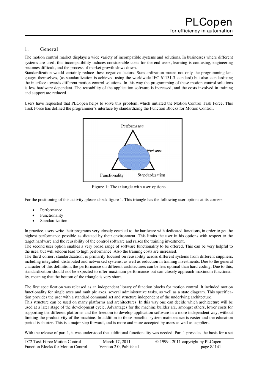
Figure 1: The triangle with user options
For the positioning of this activity, please check figure 1. This triangle has the following user options at its corners:
Performance
Functionality
Standardization.
In practice, users write their programs very closely coupled to the hardware with dedicated functions, in order to get the
highest performance possible as dictated by their environment. This limits the user in his options with respect to the
target hardware and the reusability of the control software and raises the training investment.
The second user option enables a very broad range of software functionality to be offered. This can be very helpful to
the user, but will seldom lead to high performance. Also the training costs are increased.
The third corner, standardization, is primarily focused on reusability across different systems from different suppliers,
including integrated, distributed and networked systems, as well as reduction in training investments. Due to the general
character of this definition, the performance on different architectures can be less optimal than hard coding. Due to this,
standardization should not be expected to offer maximum performance but can closely approach maximum functional-
ity, meaning that the bottom of the triangle is very short.
The first specification was released as an independent library of function blocks for motion control. It included motion
functionality for single axes and multiple axes, several administrative tasks, as well as a state diagram. This specifica-
tion provides the user with a standard command set and structure independent of the underlying architecture.
This structure can be used on many platforms and architectures. In this way one can decide which architecture will be
used at a later stage of the development cycle. Advantages for the machine builder are, amongst others, lower costs for
supporting the different platforms and the freedom to develop application software in a more independent way, without
limiting the productivity of the machine. In addition to those benefits, system maintenance is easier and the education
period is shorter. This is a major step forward, and is more and more accepted by users as well as suppliers.
With the release of part 1, it was understood that additional functionality was needed. Part 1 provides the basis for a set
TC2 Task Force Motion Control
Function Blocks for Motion Control
March 17, 2011
Version 2.0, Published
© 1999 - 2011 copyright by PLCopen
page 8/ 141
�



 2023年江西萍乡中考道德与法治真题及答案.doc
 2012年重庆南川中考生物真题及答案.doc
 2013年江西师范大学地理学综合及文艺理论基础考研真题.doc
 2020年四川甘孜小升初语文真题及答案I卷.doc
 2020年注册岩土工程师专业基础考试真题及答案.doc
 2023-2024学年福建省厦门市九年级上学期数学月考试题及答案.doc
 2021-2022学年辽宁省沈阳市大东区九年级上学期语文期末试题及答案.doc
 2022-2023学年北京东城区初三第一学期物理期末试卷及答案.doc
 2018上半年江西教师资格初中地理学科知识与教学能力真题及答案.doc
 2012年河北国家公务员申论考试真题及答案-省级.doc
 2020-2021学年江苏省扬州市江都区邵樊片九年级上学期数学第一次质量检测试题及答案.doc
 2022下半年黑龙江教师资格证中学综合素质真题及答案.doc