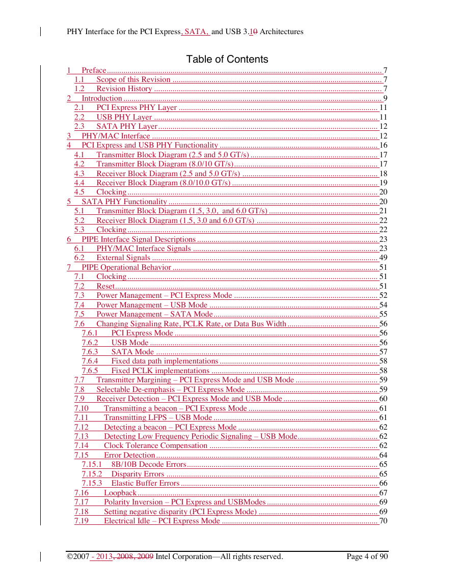
1 Preface
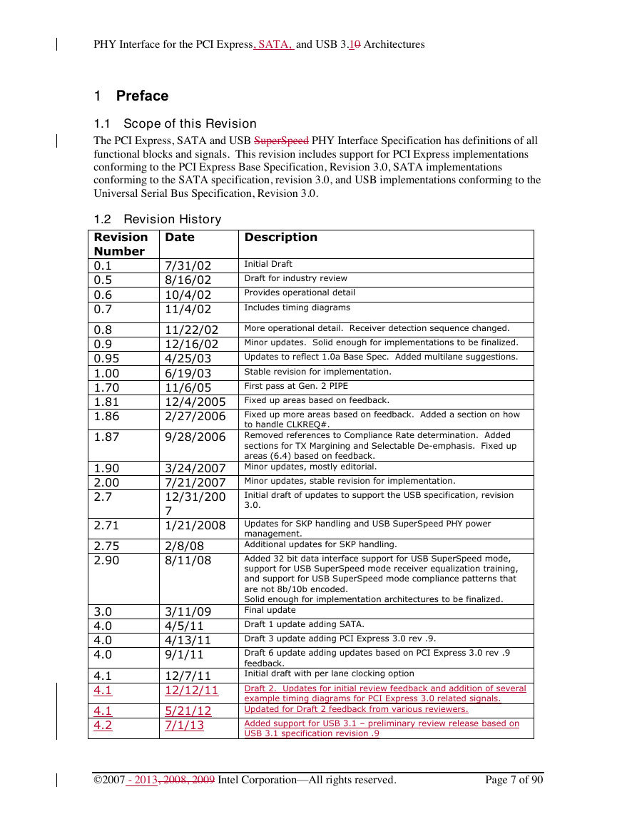
1.1 Scope of this Revision
1.2 Revision History
2 Introduction
2.1 PCI Express PHY Layer
2.2 USB SuperSpeed PHY Layer
2.3 SATA PHY Layer
3 PHY/MAC Interface
4 PCI Express and USB PHY Functionality
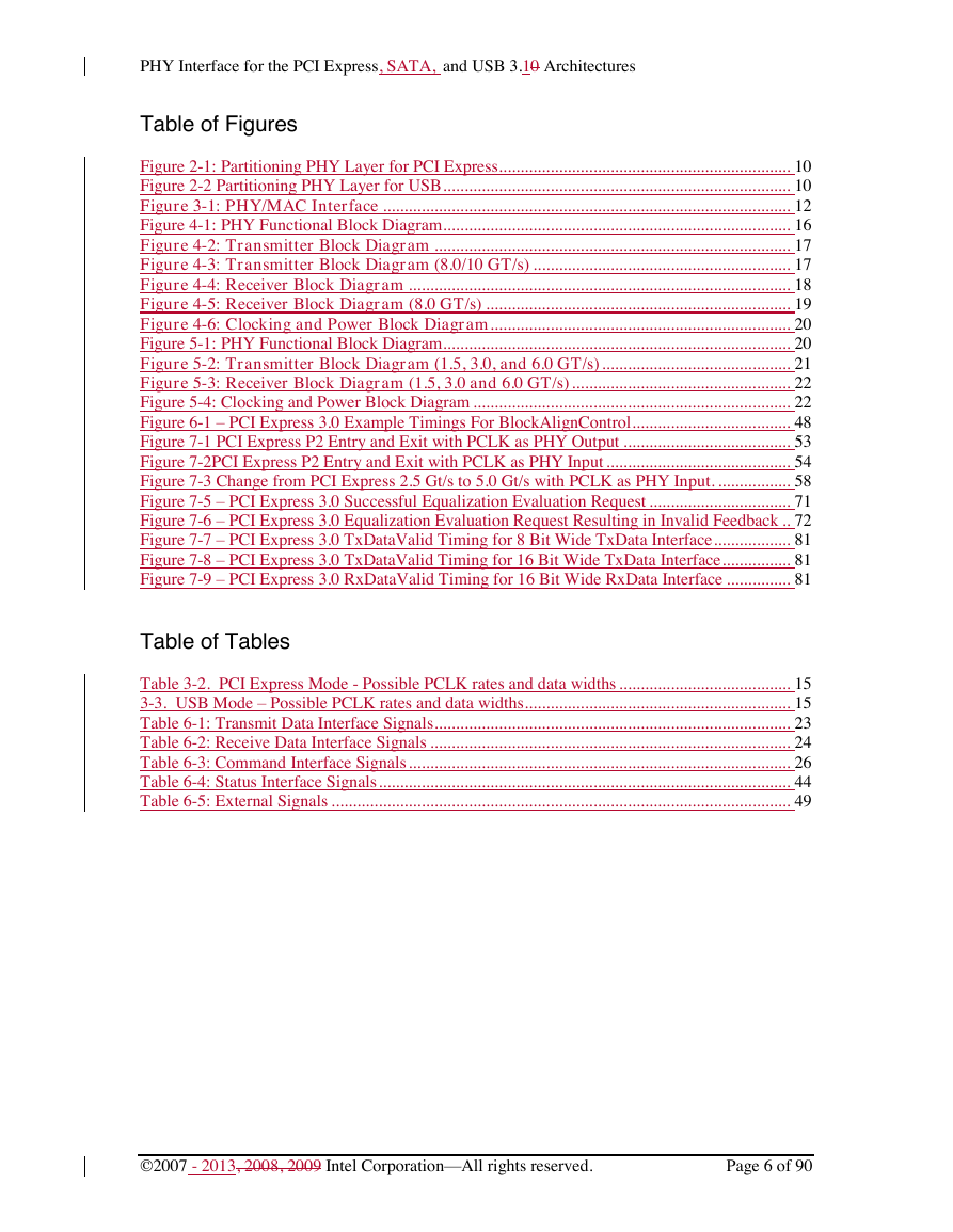
4.1 Transmitter Block Diagram (2.5 and 5.0 GT/s)
4.2 Transmitter Block Diagram (8.0/10 GT/s)
4.3 Receiver Block Diagram (2.5 and 5.0 GT/s)
4.4 Receiver Block Diagram (8.0/10.0 GT/s)
4.5 Clocking
5 SATA PHY Functionality
5.1 Transmitter Block Diagram (1.5, 3.0, and 6.0 GT/s)
5.2 Receiver Block Diagram (1.5, 3.0 and 6.0 GT/s)
5.3 Clocking
6 PIPE Interface Signal Descriptions
6.1 PHY/MAC Interface Signals
6.2 External Signals
7 PIPE Operational Behavior
7.1 Clocking
7.2 Reset
7.3 Power Management – PCI Express Mode
7.4 Power Management – USB SuperSpeed Mode
7.5 Power Management – SATA Mode
7.6 Changing Signaling Rate, PCLK Rate, or Data Bus Width
7.6.1 PCI Express Mode
7.6.2 USB Mode
7.6.3 SATA Mode
7.6.4 Fixed data path implementations
7.6.5 Fixed PCLK implementations
7.7 Transmitter Margining – PCI Express Mode and USB SuperSpeed Mode
7.8 Selectable De-emphasis – PCI Express Mode
7.9 Receiver Detection – PCI Express Mode and USB SuperSpeed Mode
7.10 Transmitting a beacon – PCI Express Mode
7.11 Transmitting LFPS – USB SuperSpeed Mode
7.12 Detecting a beacon – PCI Express Mode
7.13 Detecting Low Frequency Periodic Signaling – USB SuperSpeed Mode
7.14 Clock Tolerance Compensation
7.15 Error Detection
7.15.1 8B/10B Decode Errors
7.15.2 Disparity Errors
7.15.3 Elastic Buffer Errors
7.16 Loopback
7.17 Polarity Inversion – PCI Express and USB SuperSpeed Modes
7.18 Setting negative disparity (PCI Express Mode)
7.19 Electrical Idle – PCI Express Mode
7.20 Link Equalization Evaluation
7.21 Implementation specific timing and selectable parameter support
7.22 Control Signal Decode table – PCI Express Mode
7.23 Control Signal Decode table – USB SuperSpeed Mode
7.24 Control Signal Decode table – SATA Mode
7.25 Required synchronous signal timings
7.26 128b/130b Encoding and Block Synchronization (PCI Express 8 GT/s)
7.27 128b/132b Encoding and Block Synchronization (USB 10 GT/s)
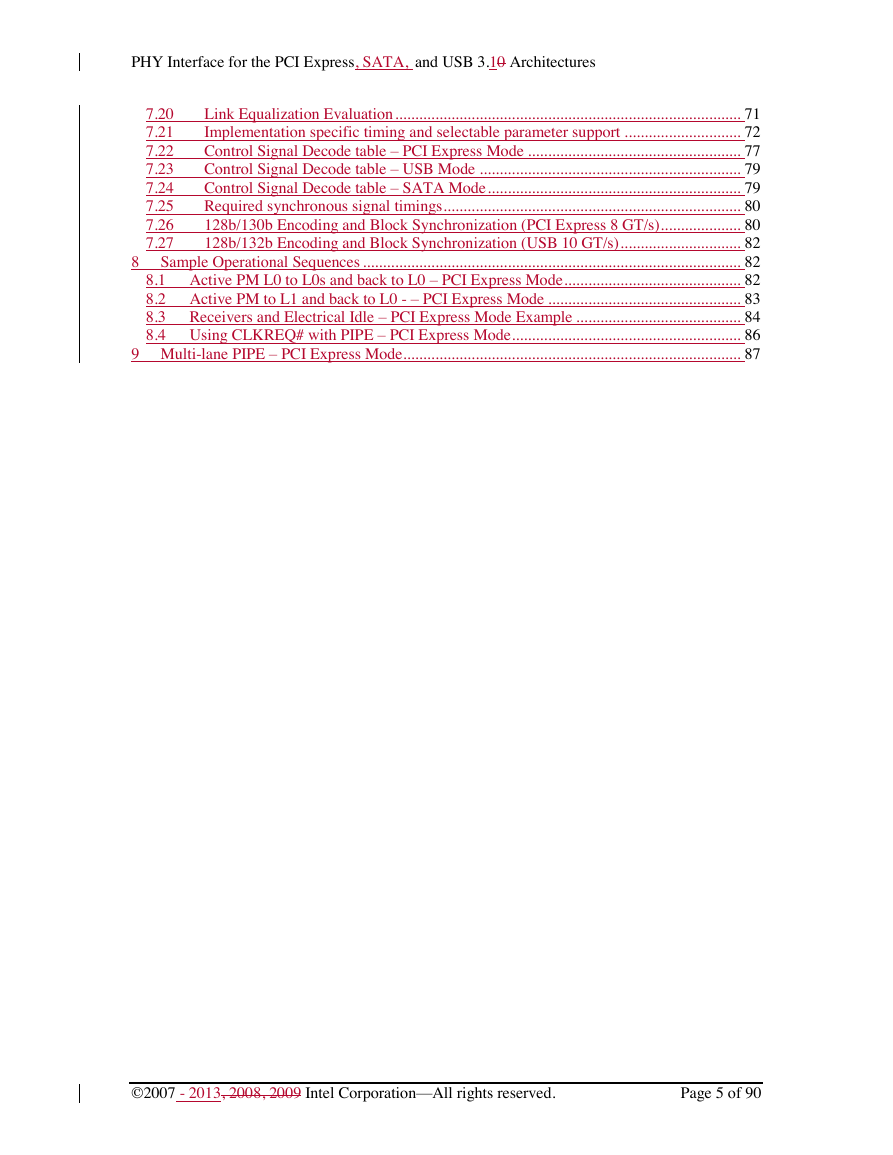
8 Sample Operational Sequences
8.1 Active PM L0 to L0s and back to L0 – PCI Express Mode
8.2 Active PM to L1 and back to L0 - – PCI Express Mode
8.3 Receivers and Electrical Idle – PCI Express Mode Example
8.4 Using CLKREQ# with PIPE – PCI Express Mode
9 Multi-lane PIPE – PCI Express Mode


 2023年江西萍乡中考道德与法治真题及答案.doc
 2012年重庆南川中考生物真题及答案.doc
 2013年江西师范大学地理学综合及文艺理论基础考研真题.doc
 2020年四川甘孜小升初语文真题及答案I卷.doc
 2020年注册岩土工程师专业基础考试真题及答案.doc
 2023-2024学年福建省厦门市九年级上学期数学月考试题及答案.doc
 2021-2022学年辽宁省沈阳市大东区九年级上学期语文期末试题及答案.doc
 2022-2023学年北京东城区初三第一学期物理期末试卷及答案.doc
 2018上半年江西教师资格初中地理学科知识与教学能力真题及答案.doc
 2012年河北国家公务员申论考试真题及答案-省级.doc
 2020-2021学年江苏省扬州市江都区邵樊片九年级上学期数学第一次质量检测试题及答案.doc
 2022下半年黑龙江教师资格证中学综合素质真题及答案.doc