Direction Cosine Matrix IMU: Theory
William Premerlani and Paul Bizard
This is the first of a pair of papers on the theory and implementation of a
direction-cosine-matrix (DCM) based inertial measurement unit for application
in model planes and helicopters. Actually, at this point, it is still a draft, there
is still a lot more work to be done. Several reviewers, especially Louis
LeGrand and UFO-man, have made good suggestions on additions and
revisions that we should make and prepared some figures that we have not
included yet. We will eventually incorporate their suggestions, but it may take
a long time to get there. In the meantime, we think there is an audience who
can benefit from what we have so far.
The motivation for DCM was to take the next step in stabilization and
control functions from an inherently stable aircraft with elevator and rudder
control, to an aerobatic aircraft with ailerons and elevator. One of the authors
(Premerlani) built a two axes board several years ago, and developed
rudimentary firmware to provide stabilization and return-to-launch (RTL)
functions for a Gentle Lady sailplane. The firmware worked well enough, and
the author came to rely on the RTL feature, but it never seemed to work as
well as the author would like. In particular, satisfactory solutions to the
following two issues were never found:
• Mixing. It was recognized that in a banked turn, there were two
problems arising from the bank angle. First, the yaw rotation of the
aircraft around the turn generated a nuisance signal in the pitch gyro,
because of the banking. Second, in order to make a level turn, the
elevator needed some “up” deflection. The amount of deflection
depends on the bank angle, which could not be directly measured.
Both issues were opposite sides of the same coin.
• Acceleration. An accelerometer measures gravity minus
acceleration. The acceleration is equal to the total of all of the
aerodynamic forces (lift, thrust, drag, etc.) on the plane, plus the
gravity force, divided by the mass. Therefore, the accelerometer
measures the negative of the total of all of the aerodynamic forces.
The measurement of gravity is what is needed to level the plane but
that is not what you get out of an accelerometer during accelerated
motion. Acceleration is a confounding variable. In particular, when
the aircraft pitches up or down, for a short while it accelerates in
such a way that the output of an accelerometer does not change.
There is a similar effect that the NASA astronauts experience when
they are in training planes. A ballistic path can produce zero net
forces and therefore fool accelerometers temporarily. The
combination of this issue and the previous one prevented really tight
DCM
1
Draft: 5/17/2009
�
pitch control, and this issue prevented the use of pitch stabilization
during a hand launch.
It was realized that part of the problem was not having a six degree of
freedom inertial measurement unit (IMU), so it was decided to design a new
board. The UAV DevBoard from SparkFun was the result.
Coincidentally, one of us (Premerlani) decided he wanted to step up to an
aircraft with ailerons, and found that he just did not have the needed flying
skills. He crashed 5 times in one summer, and had to completely replace his
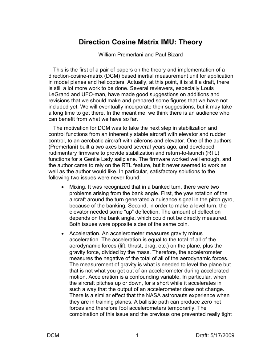
plane 3 times. So, he decided to use his new board for stabilization, shown
below, attached to his Goldberg Endurance with Velcro.
The question was, how best to do that? Working together, we came to the
same conclusion of Mahoney [1]. What is needed is a method that “fully
respects the nonlinearity of the rotation group.” Paul and I decided that we
should represent the rotation with a direction cosine matrix, that we could
maintain the elements of the matrix using gyro, accelerometer, and GPS
information, and that we could use the matrix for control and navigation. At a
high level, here is how DCM works:
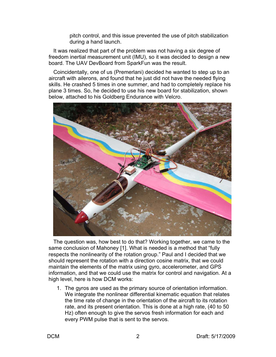
1. The gyros are used as the primary source of orientation information.
We integrate the nonlinear differential kinematic equation that relates
the time rate of change in the orientation of the aircraft to its rotation
rate, and its present orientation. This is done at a high rate, (40 to 50
Hz) often enough to give the servos fresh information for each and
every PWM pulse that is sent to the servos.
DCM
2
Draft: 5/17/2009
�
2. Recognizing that numerical errors in the integration will gradually
violate the orthogonality constraints that the DCM must satisfy, we
make regular, small adjustments to the elements of the matrix to
satisfy the constraints.
3. Recognizing that numerical errors, gyro drift, and gyro offset will
gradually accumulate errors in the DCM elements, we use reference
vectors to detect the errors, and a proportional plus integral (PI)
negative feedback controller between the detected errors and the gyro
inputs used in step 1, to dissipate the errors faster than they can build
up. GPS is used to detect yaw error, accelerometers are used to detect
pitch and roll.
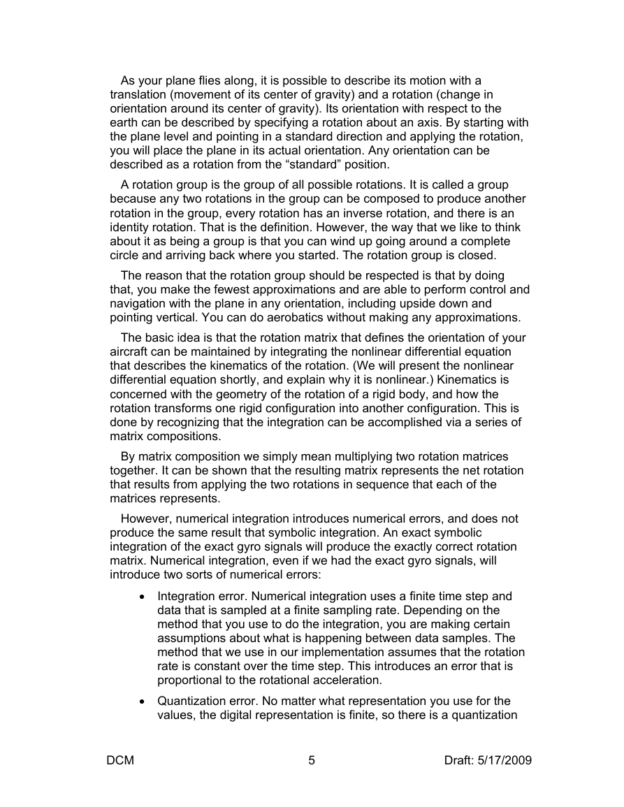
The process is shown schematically in Figure 1.
[XYZGyros]
Gyros
DriftAdjustment
W
Rmatrix
Kinematics
&Normalization
[RMatrix]
Orientation
Adjustment
Error
Error
PI Controller
Rmatrix
Yaw
Pitch Roll
Drift Detection
[GPS]
Course
[Accelerometers]
Gravity
Figure 1 Block diagram of DCM
No doubt you are wondering what a rotation group is, and why it should be
respected. You also might be wondering how you can use DCM for control
and navigation. You also might have the same questions that UFO-MAN
asked on the subject after he read Mahoney’s paper, so we will start with
those questions:
• What is a quaternion and why do we use that instead of vector
notation?
• What is meant by a rotation group?
• What is a rotation matrix?
• What does it mean to maintain orthogonality of the rotation matrix?
• What is an anti symmetric matrix?
• Can you briefly explain kinematics in this rotation matrix context?
• Can you briefly explain dynamics in this rotation matrix context?
DCM
3
Draft: 5/17/2009
�
All of this is concerned with rotations. Physically, what we are trying to do is
represent the orientation of our aircraft with respect to the earth as a rotation.
There are several ways to do this. Mahony's paper discusses two alternate
ways, rotation matrices and quaternions. Both approaches are similar in
motivation, they are representing rotations without approximations and
without singularities. Quaternions have the advantage of requiring only 4
values, while rotation matrices have 9. Rotation matrices have the advantage
of being a natural fit to control and navigation. We chose rotation matrices as
having a slight advantage, and for being more familiar to us.
R =
xb yb zb
xe ye ze
R-1 =
xe
ye
ze
xb
yb
zb
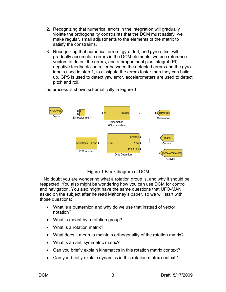
A rotation matrix describes the orientation of one coordinate system with
respect to another. The columns of the matrix are the unit vectors in one
system as seen in the other system. A vector in one system can be
transformed into the other system by multiplying it by the rotation matrix. The
transformation in the reverse direction is accomplished with the inverse of the
rotation matrix, which turns out to be equal to its transpose. (The transpose is
just the swap of rows and columns.) Unit vectors are useful in the control and
navigation computations, because their length is one. Therefore they can be
used in dot and cross products to obtain the sine or cosine of various angles.
y’ = R.y
y = R-1.y’
R-1 = tR
z
y
x
z’
y’
x’
R.R-1 = I
tR.R = I
DCM
4
Draft: 5/17/2009
�
As your plane flies along, it is possible to describe its motion with a
translation (movement of its center of gravity) and a rotation (change in
orientation around its center of gravity). Its orientation with respect to the
earth can be described by specifying a rotation about an axis. By starting with
the plane level and pointing in a standard direction and applying the rotation,
you will place the plane in its actual orientation. Any orientation can be
described as a rotation from the “standard” position.
A rotation group is the group of all possible rotations. It is called a group
because any two rotations in the group can be composed to produce another
rotation in the group, every rotation has an inverse rotation, and there is an
identity rotation. That is the definition. However, the way that we like to think
about it as being a group is that you can wind up going around a complete
circle and arriving back where you started. The rotation group is closed.
The reason that the rotation group should be respected is that by doing
that, you make the fewest approximations and are able to perform control and
navigation with the plane in any orientation, including upside down and
pointing vertical. You can do aerobatics without making any approximations.
The basic idea is that the rotation matrix that defines the orientation of your
aircraft can be maintained by integrating the nonlinear differential equation
that describes the kinematics of the rotation. (We will present the nonlinear
differential equation shortly, and explain why it is nonlinear.) Kinematics is
concerned with the geometry of the rotation of a rigid body, and how the
rotation transforms one rigid configuration into another configuration. This is
done by recognizing that the integration can be accomplished via a series of
matrix compositions.
By matrix composition we simply mean multiplying two rotation matrices
together. It can be shown that the resulting matrix represents the net rotation
that results from applying the two rotations in sequence that each of the
matrices represents.
However, numerical integration introduces numerical errors, and does not
produce the same result that symbolic integration. An exact symbolic
integration of the exact gyro signals will produce the exactly correct rotation
matrix. Numerical integration, even if we had the exact gyro signals, will
introduce two sorts of numerical errors:
•
Integration error. Numerical integration uses a finite time step and
data that is sampled at a finite sampling rate. Depending on the
method that you use to do the integration, you are making certain
assumptions about what is happening between data samples. The
method that we use in our implementation assumes that the rotation
rate is constant over the time step. This introduces an error that is
proportional to the rotational acceleration.
• Quantization error. No matter what representation you use for the
values, the digital representation is finite, so there is a quantization
DCM
5
Draft: 5/17/2009
�
error, starting at the analog to digital converter, and building
whenever you perform a calculation that does not preserve all of the
bits of the result.
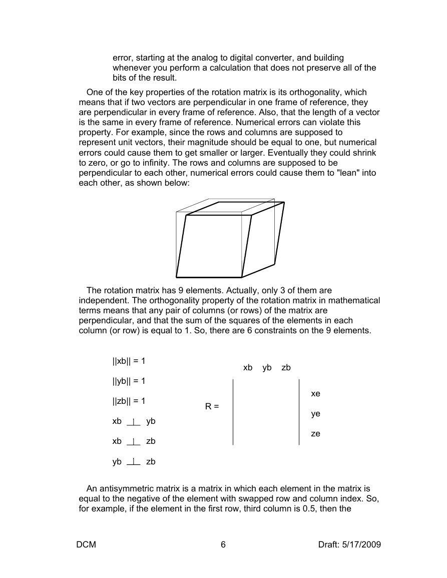
One of the key properties of the rotation matrix is its orthogonality, which
means that if two vectors are perpendicular in one frame of reference, they
are perpendicular in every frame of reference. Also, that the length of a vector
is the same in every frame of reference. Numerical errors can violate this
property. For example, since the rows and columns are supposed to
represent unit vectors, their magnitude should be equal to one, but numerical
errors could cause them to get smaller or larger. Eventually they could shrink
to zero, or go to infinity. The rows and columns are supposed to be
perpendicular to each other, numerical errors could cause them to "lean" into
each other, as shown below:
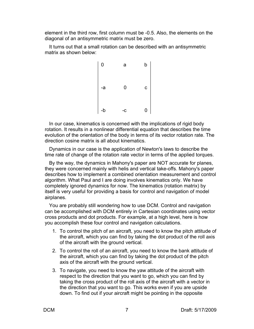
The rotation matrix has 9 elements. Actually, only 3 of them are
independent. The orthogonality property of the rotation matrix in mathematical
terms means that any pair of columns (or rows) of the matrix are
perpendicular, and that the sum of the squares of the elements in each
column (or row) is equal to 1. So, there are 6 constraints on the 9 elements.
||xb|| = 1
||yb|| = 1
||zb|| = 1
xb yb
xb zb
yb zb
xb yb zb
R =
xe
ye
ze
An antisymmetric matrix is a matrix in which each element in the matrix is
equal to the negative of the element with swapped row and column index. So,
for example, if the element in the first row, third column is 0.5, then the
DCM
6
Draft: 5/17/2009
�
element in the third row, first column must be -0.5. Also, the elements on the
diagonal of an antisymmetric matrix must be zero.
It turns out that a small rotation can be described with an antisymmetric
matrix as shown below:
0 a b
-a 0 c
-b -c 0
In our case, kinematics is concerned with the implications of rigid body
rotation. It results in a nonlinear differential equation that describes the time
evolution of the orientation of the body in terms of its vector rotation rate. The
direction cosine matrix is all about kinematics.
Dynamics in our case is the application of Newton's laws to describe the
time rate of change of the rotation rate vector in terms of the applied torques.
By the way, the dynamics in Mahony's paper are NOT accurate for planes,
they were concerned mainly with helis and vertical take-offs. Mahony's paper
describes how to implement a combined orientation measurement and control
algorithm. What Paul and I are doing involves kinematics only. We have
completely ignored dynamics for now. The kinematics (rotation matrix) by
itself is very useful for providing a basis for control and navigation of model
airplanes.
You are probably still wondering how to use DCM. Control and navigation
can be accomplished with DCM entirely in Cartesian coordinates using vector
cross products and dot products. For example, at a high level, here is how
you accomplish these four control and navigation calculations.
1. To control the pitch of an aircraft, you need to know the pitch attitude of
the aircraft, which you can find by taking the dot product of the roll axis
of the aircraft with the ground vertical.
2. To control the roll of an aircraft, you need to know the bank attitude of
the aircraft, which you can find by taking the dot product of the pitch
axis of the aircraft with the ground vertical.
3. To navigate, you need to know the yaw attitude of the aircraft with
respect to the direction that you want to go, which you can find by
taking the cross product of the roll axis of the aircraft with a vector in
the direction that you want to go. This works even if you are upside
down. To find out if your aircraft might be pointing in the opposite
DCM
7
Draft: 5/17/2009
�
direction than you want to go, take the dot product of the roll axis with
the desired direction vector. If it is negative, the aircraft is more than 90
degrees off course.
4. To find out if the aircraft is upside down, examine the sign of the dot
product of the aircraft yaw axis with the vertical. If it is less than zero,
the aircraft is upside down.
5. To find out the turning rate of the aircraft around the vertical earth axis,
transform the gyro rotation vector to the earth frame of reference, and
take the dot product with the vertical axis.
We now get deeper into the details of the theory.
Axis conventions
To describe the motion of an airplane it is necessary to define a suitable
coordinate system. For most problems dealing with aircraft motion, two
coordinate systems are used. One coordinate system is fixed to the earth and
may be considered for the purpose of aircraft motion analysis to be an inertial
coordinate system. The other coordinate system is fixed to the airplane and is
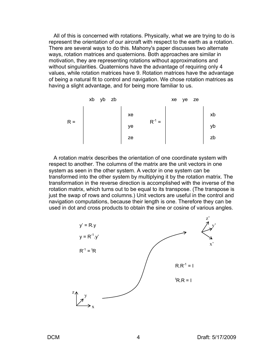
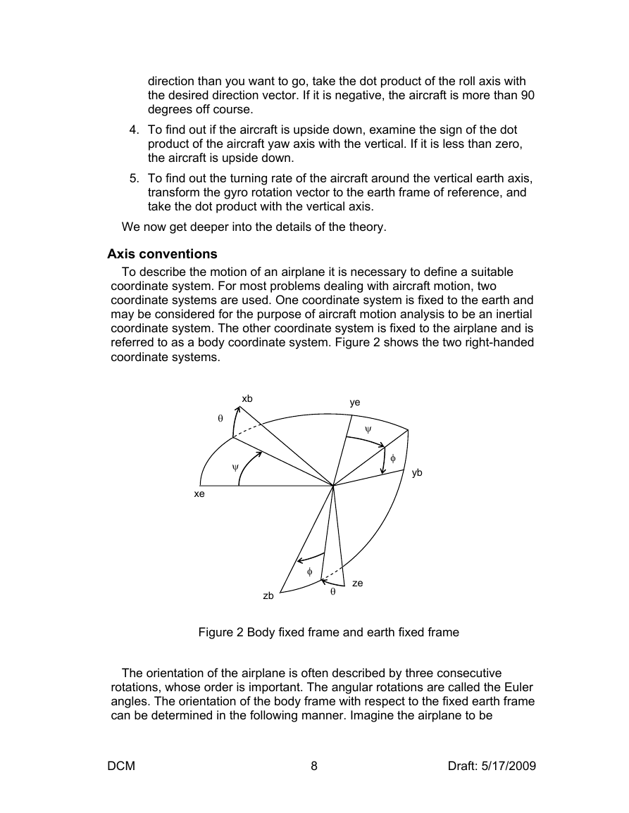
referred to as a body coordinate system. Figure 2 shows the two right-handed
coordinate systems.
xb
θ
ψ
xe
ye
ψ
φ
yb
φ
ze
θ
zb
Figure 2 Body fixed frame and earth fixed frame
The orientation of the airplane is often described by three consecutive
rotations, whose order is important. The angular rotations are called the Euler
angles. The orientation of the body frame with respect to the fixed earth frame
can be determined in the following manner. Imagine the airplane to be
DCM
8
Draft: 5/17/2009
�


 2023年江西萍乡中考道德与法治真题及答案.doc
 2012年重庆南川中考生物真题及答案.doc
 2013年江西师范大学地理学综合及文艺理论基础考研真题.doc
 2020年四川甘孜小升初语文真题及答案I卷.doc
 2020年注册岩土工程师专业基础考试真题及答案.doc
 2023-2024学年福建省厦门市九年级上学期数学月考试题及答案.doc
 2021-2022学年辽宁省沈阳市大东区九年级上学期语文期末试题及答案.doc
 2022-2023学年北京东城区初三第一学期物理期末试卷及答案.doc
 2018上半年江西教师资格初中地理学科知识与教学能力真题及答案.doc
 2012年河北国家公务员申论考试真题及答案-省级.doc
 2020-2021学年江苏省扬州市江都区邵樊片九年级上学期数学第一次质量检测试题及答案.doc
 2022下半年黑龙江教师资格证中学综合素质真题及答案.doc