logo资料库

Qualcomm WCD9335 Audio Codec Datasheet.pdf

第1页 / 共49页
第2页 / 共49页
第3页 / 共49页
第4页 / 共49页
第5页 / 共49页
第6页 / 共49页
第7页 / 共49页
第8页 / 共49页
资料共49页,剩余部分请下载后查看
Cover
Contents
Figures
Tables
Revision history
1 Introduction
1.1 Device description
1.2 Summary of key features
1.3 WCD9335 detailed functional block diagram
1.4 Supply voltage summary
1.5 Features
1.6 Terms and acronyms
2 Pad definitions
2.1 I/O parameter definitions
2.2 Pad descriptions
3 Electrical specifications
3.1 Absolute maximum ratings
3.2 Operating conditions
3.3 DC power characteristics
3.3.1 Peak current
3.4 Digital logic characteristics
3.5 Audio inputs and Tx processing
3.5.1 Analog input through digital serial interface
3.5.2 DMIC input through digital serial interface
3.6 Audio outputs and Rx processing
3.6.1 Digital serial interface through earpiece analog output
3.6.2 Digital serial interface through HPH output
3.6.3 Digital serial interface through stereo hi-fi differential line outputs
3.6.4 Digital serial interface through single-ended line output
3.7 Digital I/Os and digital processing
3.7.1 SLIMbus
3.7.2 Inter-IC sound (I2S)
3.7.3 Inter-integrated circuit (I2C)
3.7.4 Digital microphone PDM interface
3.7.5 Master clock (MCLK)
3.7.6 SoundWire
3.8 Support circuits – analog
3.8.1 Microphone bias
4 Device marking and ordering information
4.1 Device ordering information
4.1.1 Specification-compliant devices
5 Carrier, storage, & handling information
5.1 Carrier
5.1.1 Tape and reel information
5.2 Storage
5.2.1 Bagged storage conditions
5.2.2 Out-of-bag duration
5.3 Handling
5.3.1 Baking
5.3.2 Electrostatic discharge
6 PCB mounting guidelines
6.1 RoHS compliance
7 Device reliability
7.1 Reliability qualifications summary
Qualcomm Technologies, Inc. WCD9335 Audio Codec Device Specification LM80-P2751-29 Rev. A February 8, 2018 For additional information or to submit technical questions, go to: https://www.96boards.org/product/dragonboard820c/ Qualcomm Snapdragon and Qualcomm Snapdragon Voice Activation are products of Qualcomm Technologies, Inc. Other Qualcomm products referenced herein are products of Qualcomm Technologies, Inc. or its other subsidiaries. DragonBoard, Qualcomm, and Snapdragon are trademarks of Qualcomm Incorporated, registered in the United States and other countries. Other product and brand names may be trademarks or registered trademarks of their respective owners. Use of this document is subject to the license set forth in Exhibit 1. Qualcomm Technologies, Inc. 5775 Morehouse Drive San Diego, CA 92121 U.S.A. © 2018 Qualcomm Technologies, Inc. All rights reserved.
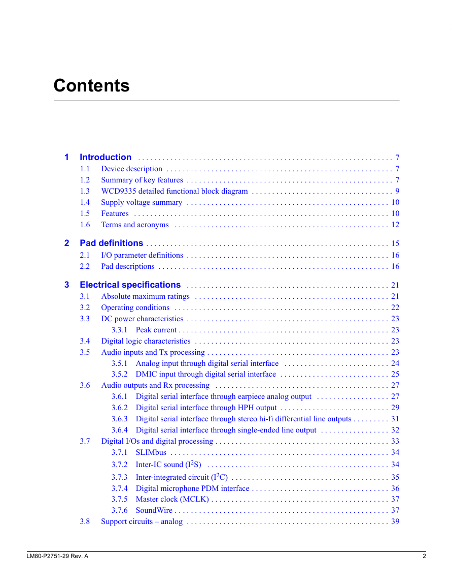
Contents 1 Introduction . . . . . . . . . . . . . . . . . . . . . . . . . . . . . . . . . . . . . . . . . . . . . . . . . . . . . . . . . . . . . . . 7 1.1 Device description . . . . . . . . . . . . . . . . . . . . . . . . . . . . . . . . . . . . . . . . . . . . . . . . . . . . . . . . 7 1.2 Summary of key features . . . . . . . . . . . . . . . . . . . . . . . . . . . . . . . . . . . . . . . . . . . . . . . . . . . 7 1.3 WCD9335 detailed functional block diagram . . . . . . . . . . . . . . . . . . . . . . . . . . . . . . . . . . . 9 1.4 Supply voltage summary . . . . . . . . . . . . . . . . . . . . . . . . . . . . . . . . . . . . . . . . . . . . . . . . . . 10 Features . . . . . . . . . . . . . . . . . . . . . . . . . . . . . . . . . . . . . . . . . . . . . . . . . . . . . . . . . . . . . . . 10 1.5 1.6 Terms and acronyms . . . . . . . . . . . . . . . . . . . . . . . . . . . . . . . . . . . . . . . . . . . . . . . . . . . . . 12 2 Pad definitions . . . . . . . . . . . . . . . . . . . . . . . . . . . . . . . . . . . . . . . . . . . . . . . . . . . . . . . . . . . . 15 I/O parameter definitions . . . . . . . . . . . . . . . . . . . . . . . . . . . . . . . . . . . . . . . . . . . . . . . . . . 16 Pad descriptions . . . . . . . . . . . . . . . . . . . . . . . . . . . . . . . . . . . . . . . . . . . . . . . . . . . . . . . . . 16 2.1 2.2 3 Electrical specifications . . . . . . . . . . . . . . . . . . . . . . . . . . . . . . . . . . . . . . . . . . . . . . . . . . 21 3.1 Absolute maximum ratings . . . . . . . . . . . . . . . . . . . . . . . . . . . . . . . . . . . . . . . . . . . . . . . . 21 3.2 Operating conditions . . . . . . . . . . . . . . . . . . . . . . . . . . . . . . . . . . . . . . . . . . . . . . . . . . . . . 22 3.3 DC power characteristics . . . . . . . . . . . . . . . . . . . . . . . . . . . . . . . . . . . . . . . . . . . . . . . . . . 23 3.3.1 Peak current . . . . . . . . . . . . . . . . . . . . . . . . . . . . . . . . . . . . . . . . . . . . . . . . . . . . 23 3.4 Digital logic characteristics . . . . . . . . . . . . . . . . . . . . . . . . . . . . . . . . . . . . . . . . . . . . . . . . 23 3.5 Audio inputs and Tx processing . . . . . . . . . . . . . . . . . . . . . . . . . . . . . . . . . . . . . . . . . . . . . 23 3.5.1 Analog input through digital serial interface . . . . . . . . . . . . . . . . . . . . . . . . . . 24 3.5.2 DMIC input through digital serial interface . . . . . . . . . . . . . . . . . . . . . . . . . . . 25 3.6 Audio outputs and Rx processing . . . . . . . . . . . . . . . . . . . . . . . . . . . . . . . . . . . . . . . . . . . 27 3.6.1 Digital serial interface through earpiece analog output . . . . . . . . . . . . . . . . . . 27 3.6.2 Digital serial interface through HPH output . . . . . . . . . . . . . . . . . . . . . . . . . . . 29 3.6.3 Digital serial interface through stereo hi-fi differential line outputs . . . . . . . . . 31 3.6.4 Digital serial interface through single-ended line output . . . . . . . . . . . . . . . . . 32 3.7 Digital I/Os and digital processing . . . . . . . . . . . . . . . . . . . . . . . . . . . . . . . . . . . . . . . . . . . 33 3.7.1 SLIMbus . . . . . . . . . . . . . . . . . . . . . . . . . . . . . . . . . . . . . . . . . . . . . . . . . . . . . . 34 3.7.2 Inter-IC sound (I2S) . . . . . . . . . . . . . . . . . . . . . . . . . . . . . . . . . . . . . . . . . . . . . 34 3.7.3 Inter-integrated circuit (I2C) . . . . . . . . . . . . . . . . . . . . . . . . . . . . . . . . . . . . . . . 35 3.7.4 Digital microphone PDM interface . . . . . . . . . . . . . . . . . . . . . . . . . . . . . . . . . . 36 3.7.5 Master clock (MCLK) . . . . . . . . . . . . . . . . . . . . . . . . . . . . . . . . . . . . . . . . . . . . 37 3.7.6 SoundWire . . . . . . . . . . . . . . . . . . . . . . . . . . . . . . . . . . . . . . . . . . . . . . . . . . . . . 37 Support circuits – analog . . . . . . . . . . . . . . . . . . . . . . . . . . . . . . . . . . . . . . . . . . . . . . . . . . 39 3.8 LM80-P2751-29 Rev. A 2
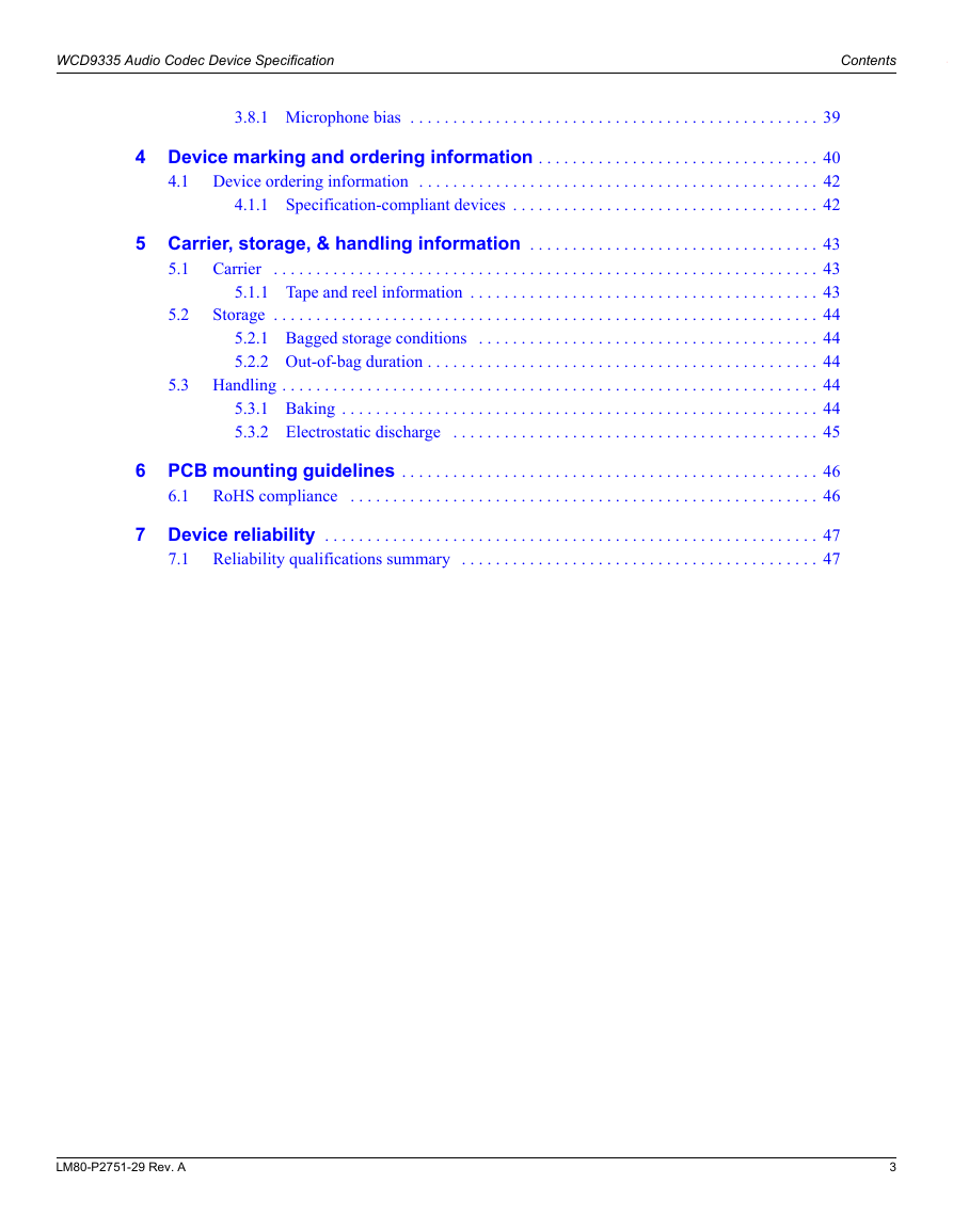
WCD9335 Audio Codec Device Specification Contents 3.8.1 Microphone bias . . . . . . . . . . . . . . . . . . . . . . . . . . . . . . . . . . . . . . . . . . . . . . . . 39 4 Device marking and ordering information . . . . . . . . . . . . . . . . . . . . . . . . . . . . . . . . . 40 4.1 Device ordering information . . . . . . . . . . . . . . . . . . . . . . . . . . . . . . . . . . . . . . . . . . . . . . . 42 4.1.1 Specification-compliant devices . . . . . . . . . . . . . . . . . . . . . . . . . . . . . . . . . . . . 42 5.2 5.1 5 Carrier, storage, & handling information . . . . . . . . . . . . . . . . . . . . . . . . . . . . . . . . . . 43 Carrier . . . . . . . . . . . . . . . . . . . . . . . . . . . . . . . . . . . . . . . . . . . . . . . . . . . . . . . . . . . . . . . . 43 5.1.1 Tape and reel information . . . . . . . . . . . . . . . . . . . . . . . . . . . . . . . . . . . . . . . . . 43 Storage . . . . . . . . . . . . . . . . . . . . . . . . . . . . . . . . . . . . . . . . . . . . . . . . . . . . . . . . . . . . . . . . 44 5.2.1 Bagged storage conditions . . . . . . . . . . . . . . . . . . . . . . . . . . . . . . . . . . . . . . . . 44 5.2.2 Out-of-bag duration . . . . . . . . . . . . . . . . . . . . . . . . . . . . . . . . . . . . . . . . . . . . . . 44 5.3 Handling . . . . . . . . . . . . . . . . . . . . . . . . . . . . . . . . . . . . . . . . . . . . . . . . . . . . . . . . . . . . . . . 44 5.3.1 Baking . . . . . . . . . . . . . . . . . . . . . . . . . . . . . . . . . . . . . . . . . . . . . . . . . . . . . . . . 44 5.3.2 Electrostatic discharge . . . . . . . . . . . . . . . . . . . . . . . . . . . . . . . . . . . . . . . . . . . 45 6 PCB mounting guidelines . . . . . . . . . . . . . . . . . . . . . . . . . . . . . . . . . . . . . . . . . . . . . . . . . 46 RoHS compliance . . . . . . . . . . . . . . . . . . . . . . . . . . . . . . . . . . . . . . . . . . . . . . . . . . . . . . . 46 6.1 7 Device reliability . . . . . . . . . . . . . . . . . . . . . . . . . . . . . . . . . . . . . . . . . . . . . . . . . . . . . . . . . . 47 Reliability qualifications summary . . . . . . . . . . . . . . . . . . . . . . . . . . . . . . . . . . . . . . . . . . 47 7.1 LM80-P2751-29 Rev. A 3
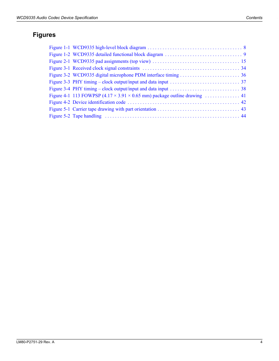
WCD9335 Audio Codec Device Specification Contents Figures Figure 1-1 WCD9335 high-level block diagram . . . . . . . . . . . . . . . . . . . . . . . . . . . . . . . . . . . . . . 8 Figure 1-2 WCD9335 detailed functional block diagram . . . . . . . . . . . . . . . . . . . . . . . . . . . . . . . 9 Figure 2-1 WCD9335 pad assignments (top view) . . . . . . . . . . . . . . . . . . . . . . . . . . . . . . . . . . . 15 Figure 3-1 Received clock signal constraints . . . . . . . . . . . . . . . . . . . . . . . . . . . . . . . . . . . . . . . 34 Figure 3-2 WCD9335 digital microphone PDM interface timing . . . . . . . . . . . . . . . . . . . . . . . . 36 Figure 3-3 PHY timing – clock output/input and data input . . . . . . . . . . . . . . . . . . . . . . . . . . . . 37 Figure 3-4 PHY timing – clock output/input and data input . . . . . . . . . . . . . . . . . . . . . . . . . . . . 38 Figure 4-1 113 FOWPSP (4.17 × 3.91 × 0.65 mm) package outline drawing . . . . . . . . . . . . . . 41 Figure 4-2 Device identification code . . . . . . . . . . . . . . . . . . . . . . . . . . . . . . . . . . . . . . . . . . . . . 42 Figure 5-1 Carrier tape drawing with part orientation . . . . . . . . . . . . . . . . . . . . . . . . . . . . . . . . . 43 Figure 5-2 Tape handling . . . . . . . . . . . . . . . . . . . . . . . . . . . . . . . . . . . . . . . . . . . . . . . . . . . . . . 44 LM80-P2751-29 Rev. A 4
WCD9335 Audio Codec Device Specification Contents Tables Table 1-1 Summary of WCD9335 device features . . . . . . . . . . . . . . . . . . . . . . . . . . . . . . . . . . . 10 Table 1-2 Terms and acronyms . . . . . . . . . . . . . . . . . . . . . . . . . . . . . . . . . . . . . . . . . . . . . . . . . . 12 Table 2-1 I/O description (pad type) parameters . . . . . . . . . . . . . . . . . . . . . . . . . . . . . . . . . . . . . 16 Table 2-2 Pad descriptions – analog inputs . . . . . . . . . . . . . . . . . . . . . . . . . . . . . . . . . . . . . . . . . 17 Table 2-3 Pad descriptions – analog outputs . . . . . . . . . . . . . . . . . . . . . . . . . . . . . . . . . . . . . . . . 17 Table 2-4 Pad descriptions – digital I/Os (other than host interfaces) . . . . . . . . . . . . . . . . . . . . . 18 Table 2-5 Pad descriptions – host digital interfaces . . . . . . . . . . . . . . . . . . . . . . . . . . . . . . . . . . 18 Table 2-6 Pad descriptions – support circuits . . . . . . . . . . . . . . . . . . . . . . . . . . . . . . . . . . . . . . . 19 Table 2-7 Pad descriptions – do not connect pads . . . . . . . . . . . . . . . . . . . . . . . . . . . . . . . . . . . . 20 Table 2-8 Pad descriptions – power supply pads . . . . . . . . . . . . . . . . . . . . . . . . . . . . . . . . . . . . . 20 Table 2-9 Pad descriptions – ground pads . . . . . . . . . . . . . . . . . . . . . . . . . . . . . . . . . . . . . . . . . . 20 Table 3-1 Absolute maximum ratings . . . . . . . . . . . . . . . . . . . . . . . . . . . . . . . . . . . . . . . . . . . . . 21 Table 3-2 Operating conditions . . . . . . . . . . . . . . . . . . . . . . . . . . . . . . . . . . . . . . . . . . . . . . . . . . 22 Table 3-3 Power supply peak current . . . . . . . . . . . . . . . . . . . . . . . . . . . . . . . . . . . . . . . . . . . . . 23 Table 3-4 Digital I/O characteristics . . . . . . . . . . . . . . . . . . . . . . . . . . . . . . . . . . . . . . . . . . . . . . 23 Table 3-5 Analog input through digital serial interface performance . . . . . . . . . . . . . . . . . . . . . 24 Table 3-6 Digital microphone input through digital serial interface performance . . . . . . . . . . . 25 Table 3-7 Serial interface through mono EAR output . . . . . . . . . . . . . . . . . . . . . . . . . . . . . . . . . 27 Table 3-8 Serial interface through HPH output . . . . . . . . . . . . . . . . . . . . . . . . . . . . . . . . . . . . . . 29 Table 3-9 Serial interface through stereo-differential line outputs . . . . . . . . . . . . . . . . . . . . . . . 31 Table 3-10 Serial interface through stereo line output . . . . . . . . . . . . . . . . . . . . . . . . . . . . . . . . 32 Table 3-11 Clock input timing requirements . . . . . . . . . . . . . . . . . . . . . . . . . . . . . . . . . . . . . . . . 34 Table 3-12 Data output timing characteristics . . . . . . . . . . . . . . . . . . . . . . . . . . . . . . . . . . . . . . . 34 Table 3-13 Data input timing requirements . . . . . . . . . . . . . . . . . . . . . . . . . . . . . . . . . . . . . . . . . 34 Table 3-14 Supported I2S standards and exceptions . . . . . . . . . . . . . . . . . . . . . . . . . . . . . . . . . . 34 Table 3-15 Master transmitter with data rate of 16 MHz . . . . . . . . . . . . . . . . . . . . . . . . . . . . . . 35 Table 3-16 Slave receiver with clock rate of 16 MHz . . . . . . . . . . . . . . . . . . . . . . . . . . . . . . . . . 35 Table 3-17 Supported I2C standards and exceptions . . . . . . . . . . . . . . . . . . . . . . . . . . . . . . . . . . 35 Table 3-18 Digital microphone timing . . . . . . . . . . . . . . . . . . . . . . . . . . . . . . . . . . . . . . . . . . . . 36 Table 3-19 Master clock (MCLK) . . . . . . . . . . . . . . . . . . . . . . . . . . . . . . . . . . . . . . . . . . . . . . . . 37 Table 3-20 PHY timing parameters (1.8 V systems) . . . . . . . . . . . . . . . . . . . . . . . . . . . . . . . . . . 38 Table 3-21 Microphone bias performance . . . . . . . . . . . . . . . . . . . . . . . . . . . . . . . . . . . . . . . . . . 39 Table 7-1 Silicon reliability results . . . . . . . . . . . . . . . . . . . . . . . . . . . . . . . . . . . . . . . . . . . . . . . 47 Table 7-2 Package reliability results . . . . . . . . . . . . . . . . . . . . . . . . . . . . . . . . . . . . . . . . . . . . . . 48 LM80-P2751-29 Rev. A 5
WCD9335 Audio Codec Device Specification Revision history Revision Date A February 2018 Initial release Description LM80-P2751-29 Rev. A 6
1 Introduction 1.1 Device description This document contains a description of the chipset capabilities. Not all features are available, nor are all features supported in the software. NOTE Enabling some features may require additional licensing fees. The WCD9335 is a stand-alone high fidelity (hi-fi) audio codec IC that supports the Qualcomm Technologies, Inc. (QTI) multimedia solutions, including the APQ8096SGE chipset. The key WCD9335 functions include the following:  Serial low-power interchip media bus (SLIMbus) for access to all on-chip digital audio channels; inter-IC sound (I2S) accesses fewer paths, but maintains compatibility with earlier integrated circuits (ICs).  SoundWire interface for driving WSA8810 or WSA8815 speaker amplifiers  Six analog input ports and seven analog output ports  Six audio analog-to-digital converters (ADCs) and seven digital-to-analog converters (DACs)  Six digital microphone inputs (three clock/data pairs)  Multibutton headset control (MBHC) for smart accessory detection  Digital processing includes the following:  Microphone activity detection (MAD) detecting audio, ultrasound, and beacon activity  Qualcomm® Voice Activation subsystem  Active noise cancellation (ANC)  Integrated analog support reduces bill of materials (BOM) and area:  Microphone bias outputs (x4) 1.2 Summary of key features WCD9335 features are listed in Table 1-1.  Lower cost, smaller footprint while enabling high-percentage digital content  Ultra low-power voice activation engine for keyword detection and user identification  Low-power, high-performance ultrasound support, including analog microphone (MIC) and line output LM80-P2751-29 Rev. A 7
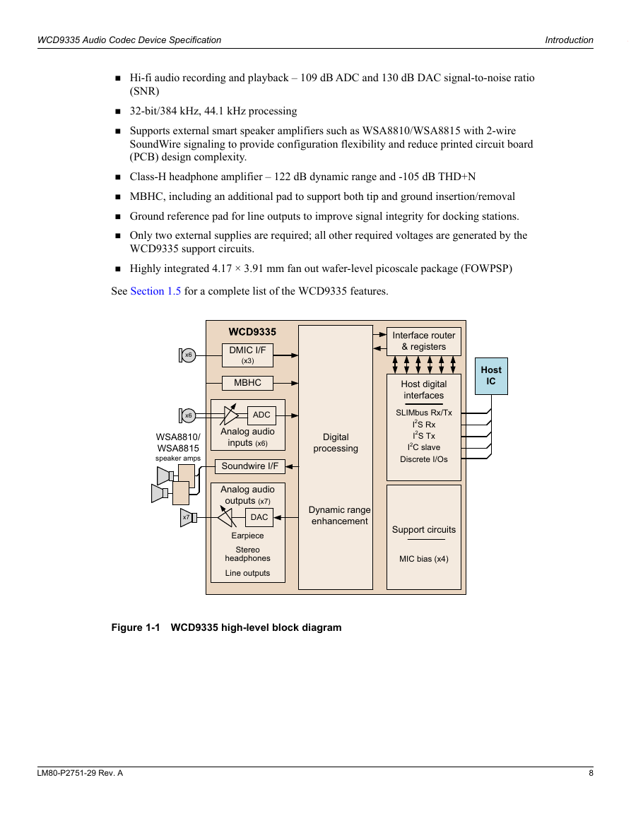
WCD9335 Audio Codec Device Specification Introduction  Hi-fi audio recording and playback – 109 dB ADC and 130 dB DAC signal-to-noise ratio (SNR)  32-bit/384 kHz, 44.1 kHz processing  Supports external smart speaker amplifiers such as WSA8810/WSA8815 with 2-wire SoundWire signaling to provide configuration flexibility and reduce printed circuit board (PCB) design complexity.  Class-H headphone amplifier – 122 dB dynamic range and -105 dB THD+N  MBHC, including an additional pad to support both tip and ground insertion/removal  Ground reference pad for line outputs to improve signal integrity for docking stations.  Only two external supplies are required; all other required voltages are generated by the WCD9335 support circuits.  Highly integrated 4.17 × 3.91 mm fan out wafer-level picoscale package (FOWPSP) See Section 1.5 for a complete list of the WCD9335 features. Figure 1-1 WCD9335 high-level block diagram LM80-P2751-29 Rev. A 8
分享到:
收藏