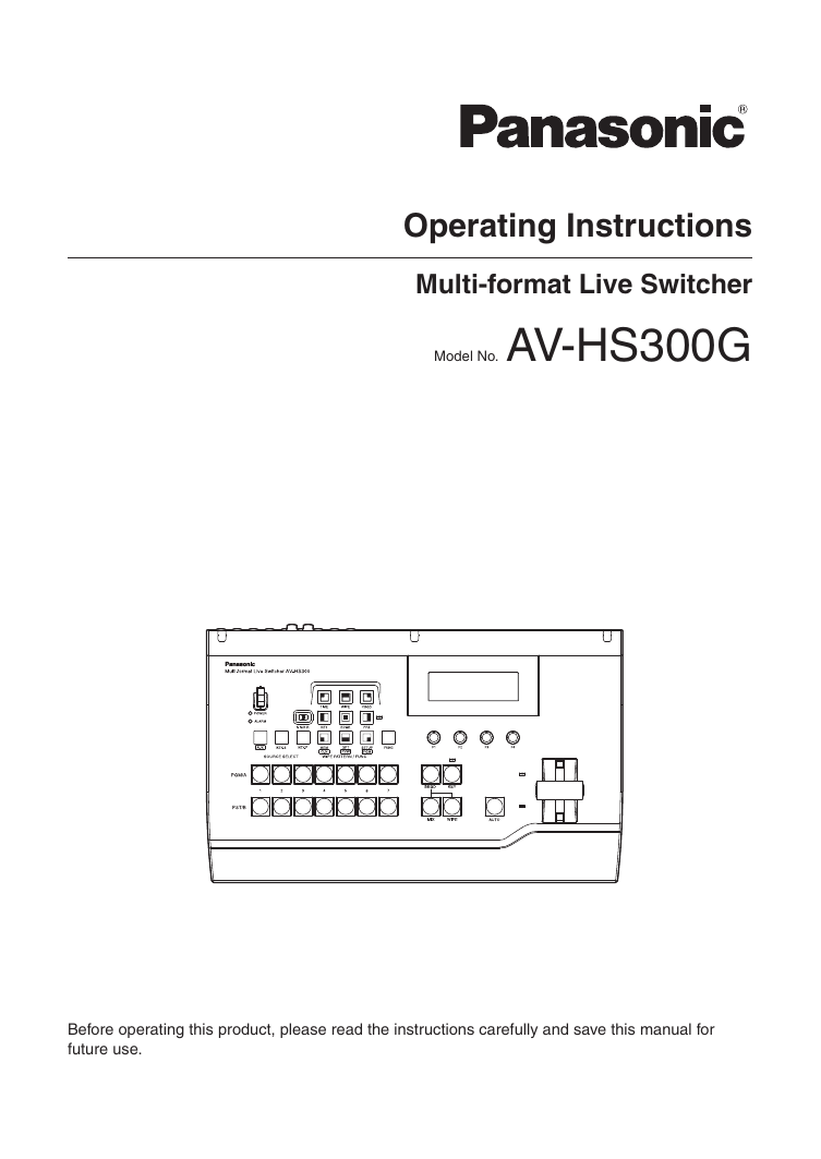
Operating Instructions
Multi-format Live Switcher
Model No. AV-HS300G
Before operating this product, please read the instructions carefully and save this manual for
future use.
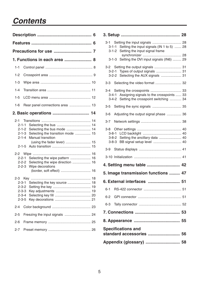
�
Safety precautions
CAUTION
RISK OF ELECTRIC SHOCK
DO NOT OPEN
CAUTION: TO REDUCE THE RISK OF ELECTRIC SHOCK,
DO NOT REMOVE COVER (OR BACK).
NO USER SERVICEABLE PARTS INSIDE.
REFER TO SERVICING TO QUALIFIED SERVICE PERSONNEL.
The lightning flash with arrowhead
symbol, within an equilateral triangle, is
intended to alert the user to the presence
of uninsulated “dangerous voltage” within
the product’s enclosure that may be of
sufficient magnitude to constitute a risk of
electric shock to persons.
The exclamation point within an equilateral
triangle is intended to alert the user to
the presence of important operating and
maintenance (service) instructions in the
literature accompanying the appliance.
For CANADA
This class A digital apparatus complies
with Canadian ICES-003.
Cet appareil numérique de la classe A
est conforme à la norme NMB-003 du
Canada.
WARNING:
• TO REDUCE THE RISK OF FIRE OR
ELECTRIC SHOCK, DO NOT EXPOSE THIS
APPARATUS TO RAIN OR MOISTURE.
• THE APPARATUS SHALL NOT BE EXPOSED
TO DRIPPING OR SPLASHING AND THAT
NO OBJECTS FILLED WITH LIQUIDS, SUCH
AS VASES, SHALL BE PLACED ON THE
APPARATUS.
WARNING:
TO PREVENT INJURY, THIS APPARATUS
MUST BE SECURELY ATTACHED TO THE
FLOOR/WALL IN ACCORDANCE WITH THE
INSTALLATION INSTRUCTIONS.
CAUTION:
TO REDUCE THE RISK OF FIRE OR SHOCK
HAZARD AND ANNOYING INTERFERENCE,
USE THE RECOMMENDED ACCESSORIES
ONLY.
indicates safety information.
�
FCC Note:
This equipment has been tested and found
to comply with the limits for a class A digital
device, pursuant to Part 15 of the FCC Rules.
These limits are designed to provide reasonable
protection against harmful interference when
the equipment is operated in a commercial
environment. This equipment generates, uses,
and can radiate radio frequency energy, and
if not installed and used in accordance with
the instruction manual, may cause harmful
interference to radio communications. Operation
of this equipment in a residential area is likely to
cause harmful interference in which case the user
will be required to correct the interference at his
own expense.
Warning:
To assure continued FCC emission
limit
compliance, the user must use only shielded
interface cables when connecting to external units.
Also, any unauthorized changes or modifications
to this equipment could void the user’s authority to
operate it.
CAUTION:
In order to maintain adequate ventilation, do
not install or place this unit in a bookcase,
built-in cabinet or any other confined space.
To prevent risk of electric shock or fire hazard
due to overheating, ensure that curtains
and any other materials do not obstruct the
ventilation.
Note:
The rating plate (serial number plate) is on
the bottom of the unit.
The socket outlet shall be installed near the
equipment and easily accessible or the mains
plug or an appliance coupler shall remain readily
operable.
A warning that an apparatus with CLASS I
construction shall be connected to a MAINS
socket outlet with a protective earthing connection.
�
Safety precautions
IMPORTANT SAFETY INSTRUCTIONS
Read these operating instructions carefully before using the unit. Follow the safety instructions on the
unit and the applicable safety instructions listed below. Keep these operating instructions handy for future
reference.
1) Read these instructions.
�) Keep these instructions.
3) Heed all warnings.
4) Follow all instructions.
5) Do not use this apparatus near water.
6) Clean only with dry cloth.
7) Do not block any ventilation openings. Install
the manufacturer's
in accordance with
instructions.
8) Do not
install near any heat sources
such as radiators, heat registers, stoves, or
other apparatus (including amplifiers) that
produce heat.
9) Do not defeat the safety purpose of the
polarized or grounding-type plug. A polarized
plug has two blades with one wider than the
other. A grounding-type plug has two blades
and a third grounding prong. The wide blade or
the third prong are provided for your safety. If
the provided plug does not fit into your outlet,
consult an electrician for replacement of the
obsolete outlet.
10) Protect the power cord form being walked on or
pinched particularly at plugs, convenience
receptacles, and the point where they exit from
the apparatus.
11) Only use attachments/accessories specified by
the manufacturer.
1�) Use only with the cart, stand,
tripod, bracket, or table specified
by the manufacturer, or sold with
the apparatus. When a cart is
used, use caution when moving
the cart/apparatus combination to
avoid injury from tip-over.
13) Unplug this apparatus during lightning storms
or when unused for long periods of time.
14) Refer all servicing to qualified service
personnel. Servicing is required when the
apparatus has been damaged in any way, such
as power-supply cord or plug is damaged,
liquid has been spilled or objects have fallen
into the apparatus, the apparatus has been
exposed to rain or moisture, does not operate
normally, or has been dropped.
indicates safety information.
3
�
Safety precautions
Information on Disposal for Users of Waste Electrical & Electronic Equipment
(private households)
This symbol on the products and/or accompanying documents means that used electrical and
electronic products should not be mixed with general household waste.
For proper treatment, recovery and recycling, please take these products to designated
collection points, where they will be accepted on a free of charge basis. Alternatively, in some
countries you may be able to return your products to your local retailer upon the purchase of an
equivalent new product.
Disposing of this product correctly will help to save valuable resources and prevent any potential negative
effects on human health and the environment which could otherwise arise from inappropriate waste handling.
Please contact your local authority for further details of your nearest designated collection point.
Penalties may be applicable for incorrect disposal of this waste, in accordance with national legislation.
For business users in the European Union
If you wish to discard electrical and electronic equipment, please contact your dealer or supplier for further
information.
Information on Disposal in other Countries outside the European Union
This symbol is only valid in the European Union.
If you wish to discard this product, please contact your local authorities or dealer and ask for the correct
method of disposal.
4
�
Contents
Description .............................................. 6
3. Setup .................................................. 28
Features ................................................... 6
Precautions for use ................................ 7
1. Functions in each area ....................... 8
3-1 Setting the input signals .............................. �8
3-1-1 Setting the input signals (IN 1 to 5) ....... �8
3-1-� Setting the input signal frame
synchronizer ........................................ �8
3-1-3 Setting the DVI input signals (IN6) ......... �9
1-1 Control panel ................................................. 8
1-� Crosspoint area ............................................. 9
3-� Setting the output signals ............................ 31
3-�-1 Types of output signals .......................... 31
3-�-� Selecting the AUX signals ..................... 31
1-3 Wipe area .................................................... 10
3-3 Selecting the video format ........................... 3�
1-4 Transition area ............................................. 11
1-5 LCD menu area ........................................... 1�
1-6 Rear panel connections area ...................... 13
3-4 Setting the crosspoints ................................ 33
3-4-1 Assigning signals to the crosspoints ...... 33
3-4-� Setting the crosspoint switching ............ 34
3-5 Setting the sync signals .............................. 35
2. Basic operations ............................... 14
3-6 Adjusting the output signal phase ............... 36
�-1 Transitions ................................................... 14
�-1-1 Selecting the bus ................................... 14
�-1-� Selecting the bus mode ......................... 14
�-1-3 Selecting the transition mode ................ 15
�-1-4 Manual transition
(using the fader lever) .......................... 15
�-1-5 Auto transition ........................................ 15
�-� Wipe ............................................................ 16
�-�-1 Selecting the wipe pattern ..................... 16
�-�-� Selecting the wipe direction ................... 16
�-�-3 Wipe decorations
(border, soft effect) ............................... 16
�-3 Key .............................................................. 18
�-3-1 Selecting the key source ........................ 18
�-3-� Setting the key ....................................... 19
�-3-3 Key adjustments .................................... 19
�-3-4 Selecting key fill ..................................... �0
�-3-5 Key decorations ..................................... �1
�-4 Color background ........................................ �3
�-5 Freezing the input signals ........................... �4
�-6 Frame memory ............................................ �5
�-7 Preset memory ............................................ �6
3-7 Network settings .......................................... 38
3-8 Other settings .............................................. 40
3-8-1 LCD backlight ........................................ 40
3-8-� Setting the ancillary data ....................... 40
3-8-3 BB signal setup level ............................. 40
3-9 Status displays ............................................ 41
3-10 Initialization ................................................. 41
4. Setting menu table ............................ 42
5. Image transmission functions ......... 47
6. External interfaces ........................... 51
6-1 RS-4�� connector ....................................... 51
6-� GPI connector ............................................. 51
6-3 Tally connector ............................................ 5�
7. Connections ...................................... 53
8. Appearance ....................................... 55
Specifications and
standard accessories ........................... 56
Appendix (glossary) ............................. 58
5
�
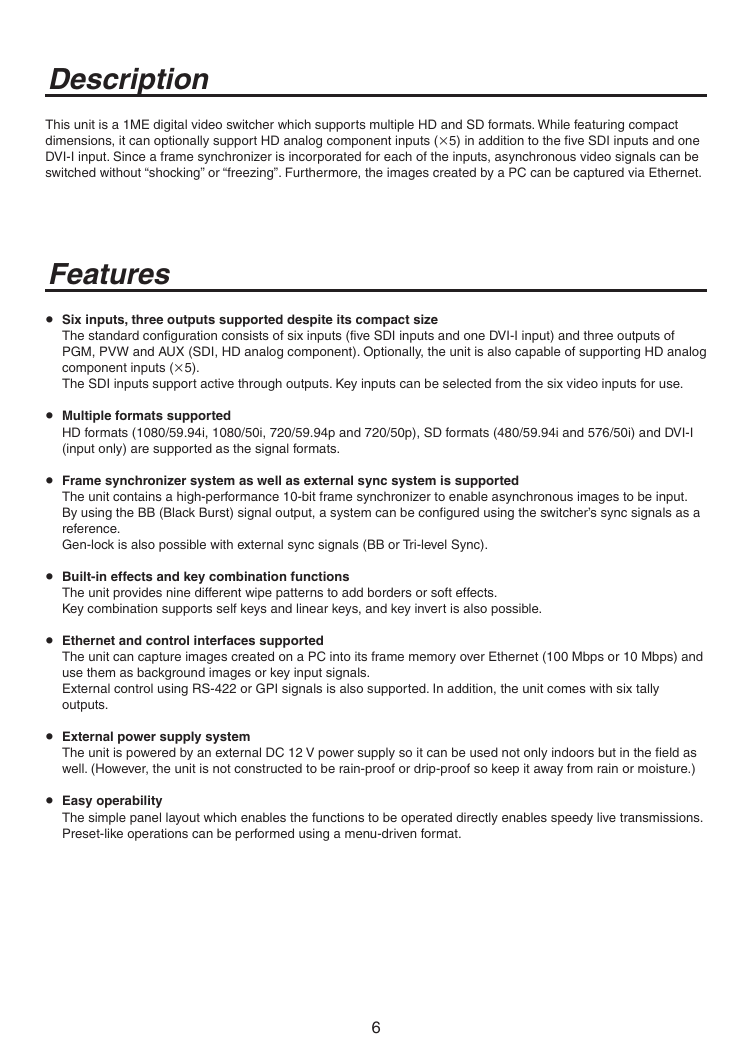
Description
This unit is a 1ME digital video switcher which supports multiple HD and SD formats. While featuring compact
dimensions, it can optionally support HD analog component inputs (5) in addition to the five SDI inputs and one
DVI-I input. Since a frame synchronizer is incorporated for each of the inputs, asynchronous video signals can be
switched without “shocking” or “freezing”. Furthermore, the images created by a PC can be captured via Ethernet.
Features
Six inputs, three outputs supported despite its compact size
The standard configuration consists of six inputs (five SDI inputs and one DVI-I input) and three outputs of
PGM, PVW and AUX (SDI, HD analog component). Optionally, the unit is also capable of supporting HD analog
component inputs (5).
The SDI inputs support active through outputs. Key inputs can be selected from the six video inputs for use.
Multiple formats supported
HD formats (1080/59.94i, 1080/50i, 7�0/59.94p and 7�0/50p), SD formats (480/59.94i and 576/50i) and DVI-I
(input only) are supported as the signal formats.
Frame synchronizer system as well as external sync system is supported
The unit contains a high-performance 10-bit frame synchronizer to enable asynchronous images to be input.
By using the BB (Black Burst) signal output, a system can be configured using the switcher’s sync signals as a
reference.
Gen-lock is also possible with external sync signals (BB or Tri-level Sync).
Built-in effects and key combination functions
The unit provides nine different wipe patterns to add borders or soft effects.
Key combination supports self keys and linear keys, and key invert is also possible.
Ethernet and control interfaces supported
The unit can capture images created on a PC into its frame memory over Ethernet (100 Mbps or 10 Mbps) and
use them as background images or key input signals.
External control using RS-4�� or GPI signals is also supported. In addition, the unit comes with six tally
outputs.
External power supply system
The unit is powered by an external DC 1� V power supply so it can be used not only indoors but in the field as
well. (However, the unit is not constructed to be rain-proof or drip-proof so keep it away from rain or moisture.)
Easy operability
The simple panel layout which enables the functions to be operated directly enables speedy live transmissions.
Preset-like operations can be performed using a menu-driven format.
6
�
Precautions for use
Handle carefully.
Do not drop the product, or subject it to strong shock or vibration.
Do not carry or move the product by the fader lever. This is important to prevent trouble.
Use the product in an ambient temperature of 32 °F to 104 °F (0 °C to 40 °C).
Avoid using the product at a cold place below 3� °F (0 °C) or at a hot place above 104 °F (40 °C) because
extremely low or high temperature will adversely affect the parts inside.
Power off before connecting or disconnecting cables.
Before plugging or unplugging the cables, be sure to switch power off.
Avoid humidity and dust.
Avoid using the product at a humid, dusty place because much humidity and dust will cause damage to the
parts inside.
Maintenance
Wipe the product using a dry cloth. To remove stubborn dirt, dip a cloth into a diluted solution of kitchen
detergent, wring it out well, and wipe the product gently. Then, after wiping the product with a moist cloth, wipe
it again with a dry cloth.
Caution
• Avoid using benzine, paint thinners and other volatile fluids.
• If a chemical cleaning cloth is to be used, carefully read through the precautions for its use.
7
�
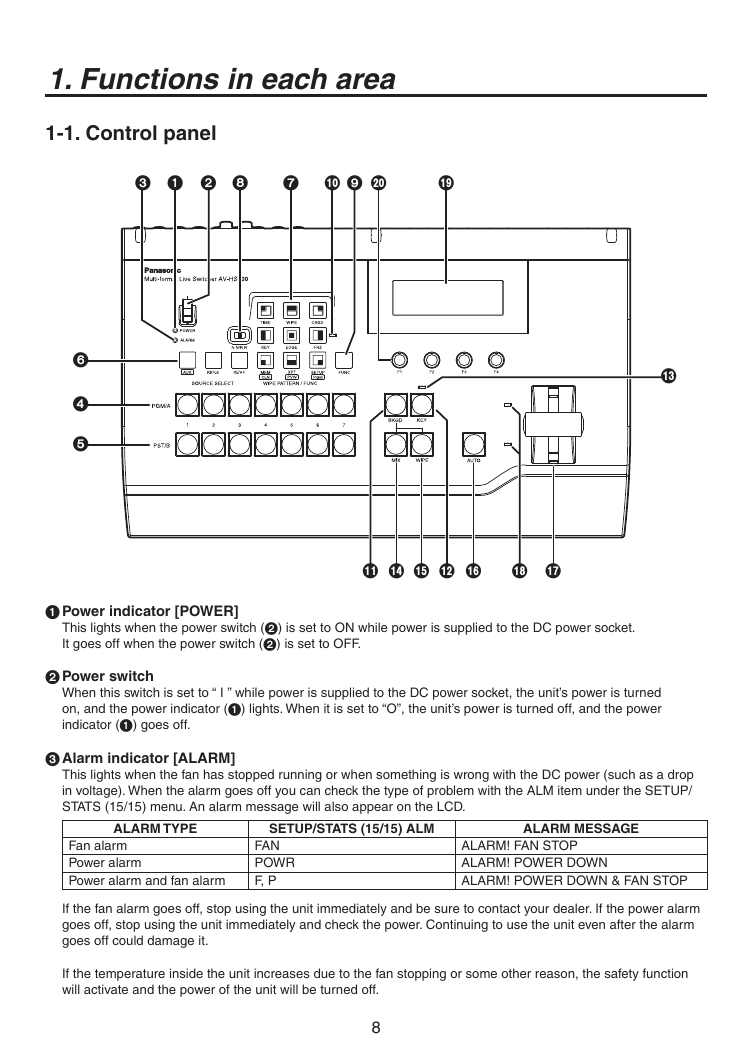
1. Functions in each area
1-1. Control panel
Power indicator [POWER]
This lights when the power switch (2) is set to ON while power is supplied to the DC power socket.
It goes off when the power switch (2) is set to OFF.
2 Power switch
When this switch is set to “ I ” while power is supplied to the DC power socket, the unit’s power is turned
on, and the power indicator () lights. When it is set to “O”, the unit’s power is turned off, and the power
indicator () goes off.
Alarm indicator [ALARM]
This lights when the fan has stopped running or when something is wrong with the DC power (such as a drop
in voltage). When the alarm goes off you can check the type of problem with the ALM item under the SETUP/
STATS (15/15) menu. An alarm message will also appear on the LCD.
ALARM TYPE
SETUP/STATS (15/15) ALM
ALARM MESSAGE
Fan alarm
Power alarm
Power alarm and fan alarm
FAN
POWR
F, P
ALARM! FAN STOP
ALARM! POWER DOWN
ALARM! POWER DOWN & FAN STOP
If the fan alarm goes off, stop using the unit immediately and be sure to contact your dealer. If the power alarm
goes off, stop using the unit immediately and check the power. Continuing to use the unit even after the alarm
goes off could damage it.
If the temperature inside the unit increases due to the fan stopping or some other reason, the safety function
will activate and the power of the unit will be turned off.
8
�


 2023年江西萍乡中考道德与法治真题及答案.doc
 2012年重庆南川中考生物真题及答案.doc
 2013年江西师范大学地理学综合及文艺理论基础考研真题.doc
 2020年四川甘孜小升初语文真题及答案I卷.doc
 2020年注册岩土工程师专业基础考试真题及答案.doc
 2023-2024学年福建省厦门市九年级上学期数学月考试题及答案.doc
 2021-2022学年辽宁省沈阳市大东区九年级上学期语文期末试题及答案.doc
 2022-2023学年北京东城区初三第一学期物理期末试卷及答案.doc
 2018上半年江西教师资格初中地理学科知识与教学能力真题及答案.doc
 2012年河北国家公务员申论考试真题及答案-省级.doc
 2020-2021学年江苏省扬州市江都区邵樊片九年级上学期数学第一次质量检测试题及答案.doc
 2022下半年黑龙江教师资格证中学综合素质真题及答案.doc