See discussions, stats, and author profiles for this publication at: https://www.researchgate.net/publication/264198235
Detail enhancement for high-dynamic-range
infrared images based on guided image filter
ARTICLE in INFRARED PHYSICS & TECHNOLOGY · NOVEMBER 2014
Impact Factor: 1.55 · DOI: 10.1016/j.infrared.2014.07.013
CITATIONS
3
2 AUTHORS:
READS
203
Ning Liu
Nanjing University of Posts and Telecomm…
Dongxue Zhao
Greenville College
17 PUBLICATIONS 14 CITATIONS
17 PUBLICATIONS 10 CITATIONS
SEE PROFILE
SEE PROFILE
All in-text references underlined in blue are linked to publications on ResearchGate,
letting you access and read them immediately.
Available from: Dongxue Zhao
Retrieved on: 11 April 2016
�
Infrared Physics & Technology 67 (2014) 138–147
Contents lists available at ScienceDirect
Infrared Physics & Technology
j o u r n a l h o m e p a g e : w w w . e l s e v i e r . c o m / l o c a t e / i n f r a r e d
Detail enhancement for high-dynamic-range infrared images based on
guided image filter
Ning Liu a,⇑
, Dongxue Zhao b
a Nanjing XiaoZhuang University, College of Physics & Electronics, Nanjing, Jiangsu Province 211171, China
b University of Missouri-St. Louis, Department of Physics and Astronomy, St. Louis, MO 63121, United States
h i g h l i g h t s
� New detail enhancement algorithm has been raised in this paper.
� Greatly simplified the computation process to the existing methods.
� Better noise suppression when enhancing the detail of IR images.
� Effective in enhancing the detail information of IR images.
a r t i c l e
i n f o
a b s t r a c t
Article history:
Received 18 March 2014
Available online 24 July 2014
Keywords:
Detail enhancement
Guided image filter
Noise reduction
Infrared images
High dynamic range
Detail enhancement and noise reduction play crucial roles in high dynamic range infrared image process-
ing. The main focuses are to compress the high dynamic range images with an effective way to display on
lower dynamic range monitors, enhance the perceptibility of small details, and reduce the noises without
causing artifacts. In this paper, we propose a new method for detail enhancement and noise reduction of
high dynamic range infrared images. We first apply a guided image filter to smooth the input image and
separate the image into the base component and the detail component. This process also gives us an
adaptive weighting coefficient associated with the details generated by the filter kernel. After the filtering
process, we compress the base component into the display range by our modified histogram projection
and enhance the detail component using the gain mask of the filter weighting coefficient. At last, we
recombine the two parts and quantize the result to 8-bit domain. Our method is significantly better than
those based on histogram equalization (HE), and it also has better visual effect than bilateral filter-based
methods. Furthermore, our proposed method is much faster, non-approximate and suffers much less gra-
dient flipping artifacts compared to the bilateral filter-based methods because the guided image filter
uses the local linear model. We demonstrate that our method is both effective and efficient in a great
variety of applications. Experimental verification and detailed analysis are shown in this paper.
Ó 2014 Elsevier B.V. All rights reserved.
1. Introduction
Nowadays, high-quality thermal cameras can detect tempera-
ture difference within 0.01 K. They can also accommodate the tem-
perature range about 50 K. For these reasons, modern infrared
cameras are able to produce images with a wide dynamic range
of 14-bit (or more), which exceeds the 8-bit sensitivity of a typical
display device. Nevertheless, a human visual system only has the
capability of distinguishing 128 gray levels of an image [1]. Hence,
we need a procedure to compress the dynamic range of the raw
images into a lower range. Thus, it is suitable for the display
⇑ Corresponding author.
E-mail address: coolboy006@sohu.com (N. Liu).
http://dx.doi.org/10.1016/j.infrared.2014.07.013
1350-4495/Ó 2014 Elsevier B.V. All rights reserved.
system and enhances the significant details of images during the
compressing and then improve the image visual quality.
Dynamic-range compression (DRC) has been widely investi-
gated and a number of visualization techniques have been pro-
posed in literature. Such techniques are applied specifically in
the visible spectral domain and take no account of the characteris-
tics of infrared images. Thus, specific technology must be studied
especially for high dynamic range infrared images, which will be
useful for adjusting the raw data into a proper range for display
and maintaining or even improving objects’ visibility and overall
contrast.
Traditional gamma correction is a widely used for contrast
enhancement owing to its simplicity and the convenience of dis-
playing infrared images in real-time system. It improves image
�
N. Liu, D. Zhao / Infrared Physics & Technology 67 (2014) 138–147
139
contrast through a specified gamma correction curve [2]. Other
widely used methods are automatic gain control (AGC) and histo-
gram equalization (HE)-based method [10,15–17]. The AGC
method is quite simple. It removes extreme values and linearly
compresses the raw data to a display range [18]. Unlike the AGC,
HE employs non-linear and non-monotonic transfer functions to
map the pixel intensity values between the input and output
images. A large number of algorithms derived from HE are aimed
to overcome the drawbacks of HE [3,4] such as increasing noises,
losing details and washing out effect in some homogeneous areas.
Technically, they can be categorized into two types: the global HE
(GHE) and the local HE (LHE) [14]. The plateau histogram equaliza-
tion (PHE) [21,22] and brightness preserving bi-HE (BPBHE) belong
to the traditional GHE. They can suppress the enhancement of
homogeneous regions by involving some tuning parameters. Com-
pared to the GHE methods, the LHE techniques also act as the same
role in display wide dynamic range infrared images. LHE applies
histogram equalization in the local region of an image. This makes
the image quality superior to GHE but has high computational
expense and complexity. Adaptive histogram equalization (AHE)
[3] can improve the local contrast and bring out more details of
the image by computing the histogram through a local window
centered at a given pixel to determine the mapping for this pixel.
But it produces significant noises during processing. The improved
AHE: contrast limited AHE (CLAHE) [4] has more flexibility in
choosing the local histogram mapping function, and it can reduce
undesired noise amplification. A novel contrast enhancement
method called partially overlapped sub-block HE (POSHE) [5] has
the capability to highlight the local details, and it dramatically
reduces the computational time. All in all, these aforementioned
HE-based methods could compress the dynamic range of the raw
images more effectively than AGC. Given that they just process
the images based on histogram information, obviously they cannot
do a satisfactory job for detail enhancement.
In order to enhancing details while compressing dynamic range,
some advanced methods are proposed. The balanced CLAHE and
contrast enhancement (BCCE) [6] as well as the bilateral filter
and dynamic range partitioning (BF&DRP) [7] are two methods
for visualizing high dynamic range infrared images proposed by
Branchitta et al.
images are
smoothed into the base component and the detail component by
a bilateral filter. The detail component is acquired by subtracting
the base component from the input images. Then the two compo-
nents are processed independently through a set of tunable param-
eters. These parameters should be carefully tuned to adjust the
visualization system for the specific scenario.
In the BF&DRP method,
input
Recently, Zuo et al. [8] proposed a novel method of display and
detail enhancement for high-dynamic-range infrared images based
on the framework of BF&DRP; here we call
it BF&DDE. This
approach is clearly superior in detail protection and noise reduc-
tion than other methods. It separates the raw image into two com-
ponents using a modified bilateral filter, and then processes each
component independently. The base component is projected to
the display range, and the detail component is added back after
an adaptive gain control process. Because of the mechanism of
the bilateral filter, the gradient flipping artifacts are produced.
The BF&DDE uses an adaptive Gaussian filtering (AGF) to avoid
the unwanted artifacts. We found in our experiments that the
AGF can suppress the gradient flipping artifacts to a certain extent
but could not completely avoid it. In some particular scene with
strong edges, the gradient flipping artifacts can be very annoying.
Besides, the high computation cost of the bilateral filter and the
AGF makes the actual application of BF&DDE restricted. For these
reasons, a new method of display and detail enhancement for high
dynamic range infrared images is proposed. We use the guided
image filter (GIF) instead of the bilateral filter (BF). Its advantages
include as follows: first, the GIF is a fast and non-approximate lin-
ear algorithm, its computational complexity is independent of the
filtering kernel size [9]. Second, we use a mask as detail identifier
to enhance the detail component adaptively, and set independent
tuning parameters during the filtering process. The proposed
method can be more flexible to reduce the background noises. This
method can achieve the great effect of detail enhancement and
noise reduction, and furthermore, works better near strong edges.
2. The principle of the proposed algorithm
He et al. [9] has proposed a novel filter, the guided image filter
(GIF), which is widely applicable in computer vision and graphics.
As they said, the GIF not only do a great job in edge-preserving but
also can be computed efficiently. Inspired by the sensational effect
of the BF&DDE [8] in high dynamic range infrared images processing,
we design the framework of our method and improve it. We first use
a GIF to smooth the input image and treat the result as a base layer,
which contains the large amplitude variations which must be com-
pressed. The subtraction of the input image and the base layer is then
determined as the detail layer. The detail layer must be expanded
because it contains the small signal variations related to fine texture.
We process the two layers respectively and recombine them at last.
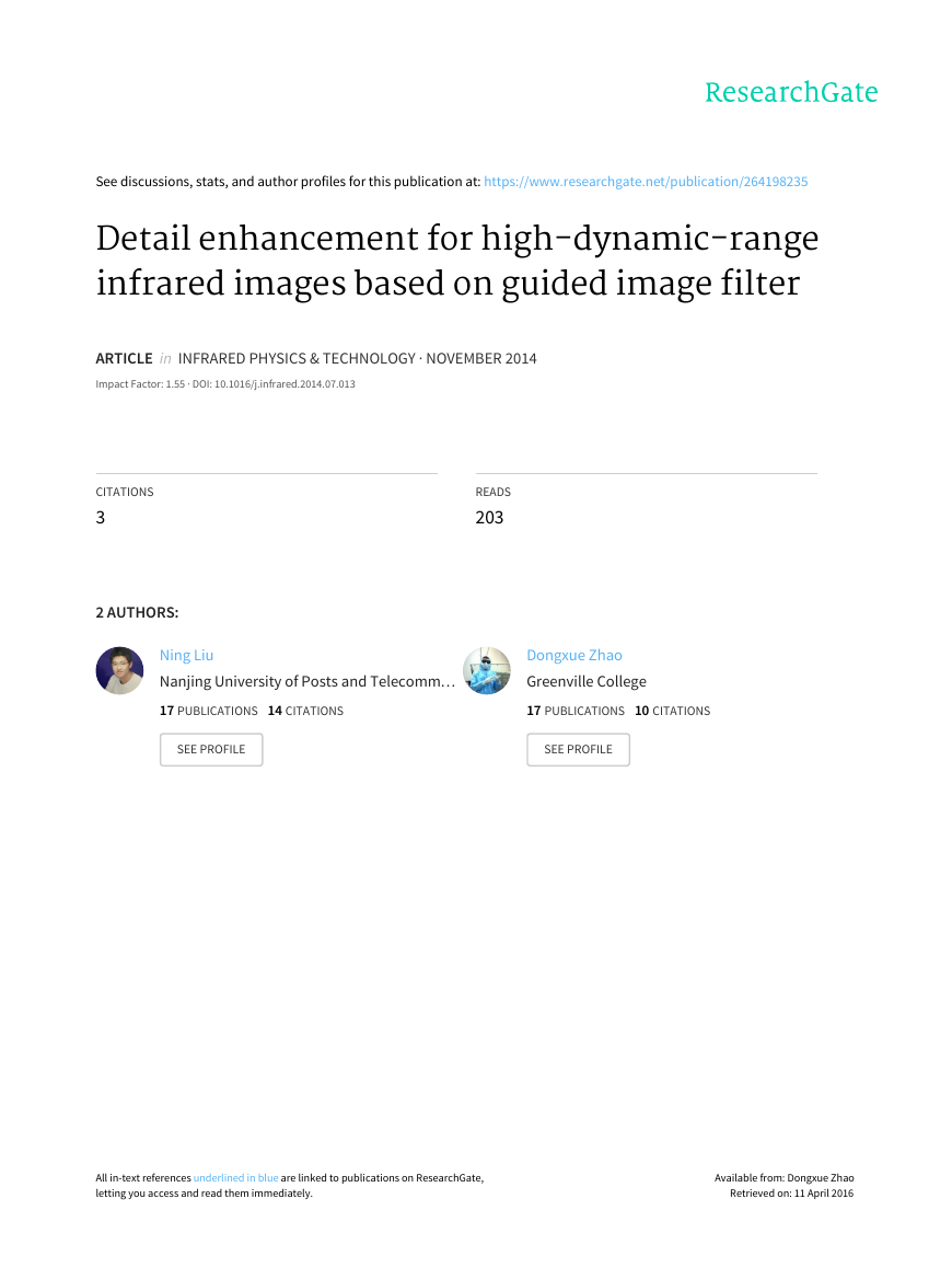
Fig. 1 illustrates the intact principle scheme.
The key assumption of the GIF is a local linear model between
the guidance image G and the filtered output Igif. The guidance G
can be acquired from the adjacent image or the input image Iin
itself. When Iin and G are identified, the expression of the GIF is for-
mulated as follow:
Igifði; jÞ ¼
; j0ÞIin:
X
W Gði0
ð1Þ
ði0;j0Þ2wi;j
The notation ði0
; j0Þ 2 wi;j indicates that ði0
; j0Þ are pixels in a fil-
ter window that centered at the pixel ði; jÞ. W Gði0
; j0Þ is the kernel
weights function which can be used as the weighting coefficient to
enhance the details. We regard the filter output Igif as the base
component IB. Then, the detail component ID is merely obtained as:
IDði; jÞ ¼ Iinði; jÞ � IBði; jÞ:
ð2Þ
We process the two components separately. The base layer is
mapped into the proper range using modified histogram projection
with a threshold and a displacement factor, then we get the result
IBP. Meanwhile the detail layer is enhanced using the adaptive gain
control method and we get the result IDP. Finally, the two layers are
recombined and regulated linearly to the proper range for display:
ð3Þ
Iout ¼ IBP þ IDP;
The detail layer only has a small range, we can just compress
the base layer to a lower range in case that when the detail layer
is added back, the results would not overflow. Here the process
is quite flexible and diverse.
3. Guided image filtering techniques
3.1. Filtering process
The GIF [9] is a linear translation-variant filter and Eq. (1) is its
general expression. In Eq. (1), the kernel weights can be explicitly
expressed by:
;j0Þ¼ 1
jwj2
!
;j0Þ�li0;j0Þ
;j00Þ�li0;j0ÞðIinði0
ri0;j0 þe
1þðIinði00
X
W Gði0
;
ði00
ði00
;j00Þ2 wi;j;
;j00Þ2 wi0;j0
ð4Þ
�
140
N. Liu, D. Zhao / Infrared Physics & Technology 67 (2014) 138–147
Fig. 1. Flowchart of our algorithm. The blue arrows indicate that these modules are controlled or can be adjusted by the parameters or the filter kernel weights. (For
interpretation of the references to color in this figure legend, the reader is referred to the web version of this article.)
X
where w is the number of pixels in the window wi;j, a square win-
dow of a radius r, li0;j0 and ri0;j0 are the mean and variance of Iin in
wi0;j0 . e is a regularization parameter to describe the smoothing level
of the filter. The linear model of this filter output can be shown as
follows:
Igifði; jÞ ¼ 1
j
wj
X
Here, aði0 ;j0Þ and bði0 ;j0Þ are linear coefficients assumed to be con-
stant in wi0;j0 . They can be given by:
; j0Þ þ bði0
; j0ÞIinði0
ði0;j0Þ2wi;j
; j0ÞÞ:
ðaði0
ð5Þ
1
wj
j
ði0;j0Þ2wi;j
aði; jÞ ¼
Iinði0
; j0ÞGði0
; j0Þ � li;jIinði0
; j0Þ
ri;j þ e
:
ð6Þ
bði; jÞ ¼ Iinði0
; j0Þ � aði; jÞli;j:
ð7Þ
From Eqs. (5)–(7), we can get the output value of the GIF. As He
et al. [9] mentioned that because of the linear coefficients are vary-
ing spatially, rIgif is no longer the scaling of rIin. Since the linear
coefficients are the output of an average filter, their gradients
should be much smaller than those of Iin near strong edges. In this
situation we can still have rIgif � �arIin. It means that abrupt
intensity changes in Iin can be mostly maintained in Igif. The
edge-preserving property can be seen from the equations above:
if a pixel is in the middle of a ‘‘high variance’’ area, its value will
be unchanged. Meanwhile, if it is in the middle of a ‘‘flat patch’’
area, its value becomes the average of the pixels nearby. The
parameter e becomes the criterion of ‘‘flat patch’’ and ‘‘high vari-
ance’’. When the patches’ variance ðr2Þ is much smaller than e,
they will be smoothed. On the contrary, those with variance much
larger than e are preserved. The parameter e and the window size
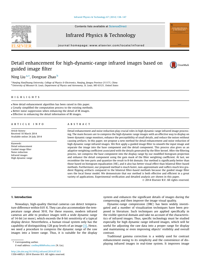
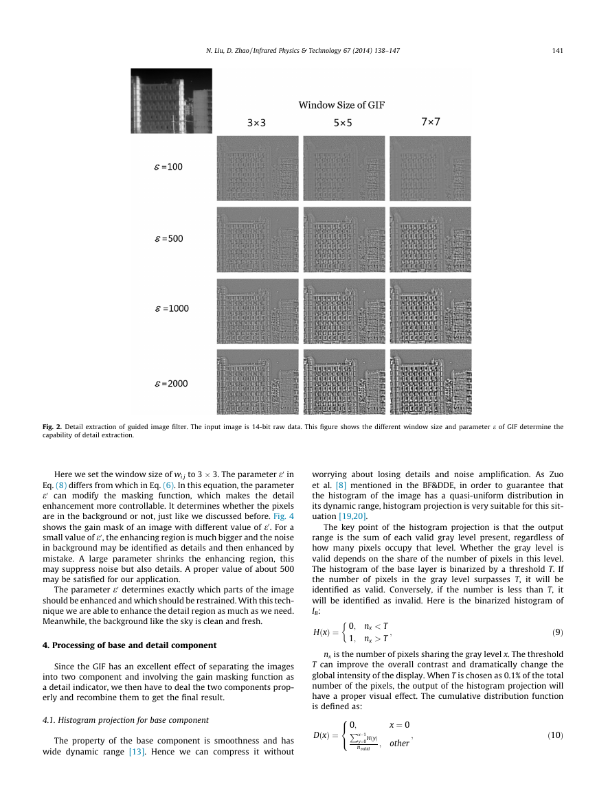
determine the capability of detail extraction. Fig. 2 shows this
capability with different values. Unlike the visible images, infrared
images often have the characteristic of edge blur. Since the
smoothing effect increases when the size of the filter window is
getting larger, the radius r should not be a large value in case of
the blurred images become more blurry. When e is set to a small
value like 100, the detail layer consists of small details such as
background noises and tiny structures. A large window size with
a large e will ignore some textures and pay much attention to
strong edges. As for our application in infrared images, a small win-
dow size with a large e will give us a satisfied detail layer.
3.2. Filter kernel weights analysis
The ability of the edge-preserving can be understood by inves-
tigating the filter kernel. Eq. (4) shows the property. When the two
pixels Iinði00
; j0Þ are on the same side of an edge, the
terms Iinði00
; j0Þ � li0;j0 have the same signs (±).
Otherwise, they have opposite signs. Therefore, the term
; j00Þ and Iinði0
; j00Þ � li0 ;j0 and Iinði0
1 þ ðIinði00
; j0Þ � li0;j0ÞðIinði0
ri0;j0 þ e
; j0Þ � li0;j0Þ
is much smaller when two pixels are on different sides than on the
same sides [9,11]. For ‘‘flat patch’’ with small scale textures, the fil-
ter acts like a low-pass filter. However, when pixels across an edge,
the kernel assigns nearly zero weights to those on the opposite
sides, they are almost not averaged together [12].
A good advantage of guided filter compared to bilateral filter is
that it avoids the gradient flipping artifacts. We choose a real cap-
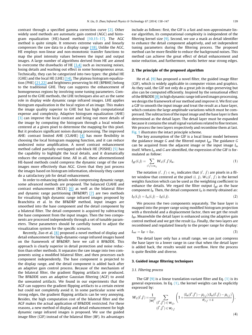
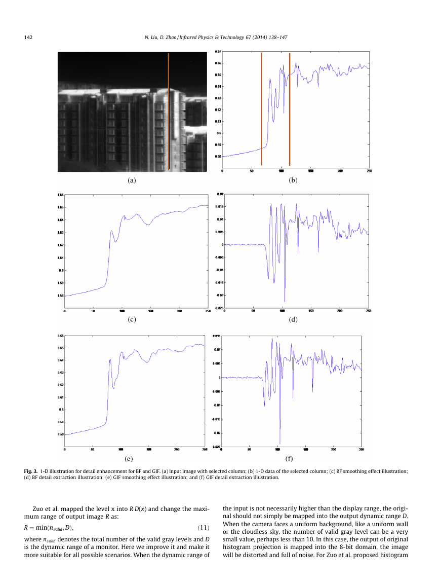
tured frame and conduct the two filter separately. The plots show
the filtering effect of them. The red1 line in Fig. 3(a) indicates the
sampling column. The process result by these two filter are shown
in Fig. 3(c–f). The data in selected region of Fig. 3(b) are processed
and shown in Fig. 3(c–f). We can see that for the bilateral filter,
the base layer is not consistent with input signal at the edge pixels
because few pixels around them have similar gray levels and the
Gaussian weighted average has little statistical data and becomes
unreliable. This causes great fluctuations in detail layer, and the
recombined signal has reversed gradients. For guided filter, the gra-
dient of the base layer is nearly linear around the edge, so it pre-
serves the gradient information better. The shape of the edge is
well maintained in the recombined layer (see Fig. 3).
Most detail enhancement processing based on GIF are merely
for visible images which contain little noises. For infrared images,
simply enhance the detail component will inescapably lead to an
unacceptable amplification of the noise in homogeneous region
of the image. In order to obtain visually optimal results, the prop-
erties of the visual system should be incorporated into the
enhancement algorithm.
3.3. Gain mask technique
Zuo et al. proposed an adaptive gain control method for detail
component in his BF&DDE in Ref. [8]. They simply employed the nor-
malized weighting coefficient of the bilateral filter to act as the mask
to enhance the detail layer. In the smooth region of the image, the
gain of the detail is set low to avoid the over amplification of the
noise. Otherwise, in the high spatial active area, the gain of the detail
is set high to enhance the image’s visual effect. Usually the gain
range is set from 1 to 2.5. The background, like the sky region, has
the values of gain near 1, which prevents amplification of noise. Here
we propose a new method to identify the details and background.
We noticed that the kernel of the GIF somehow reflects the spatial
detail of the image. We simplify the kernel as follows:
Wði; jÞ ¼ 1
wj
j
ðIði; jÞ � lm;nÞ2
X
!
ð8Þ
m;n þ e0
r2
:
ðm;nÞ2wi;j
1 For interpretation of color in Fig. 2, the reader is referred to the web version of
this article.
�
N. Liu, D. Zhao / Infrared Physics & Technology 67 (2014) 138–147
141
Fig. 2. Detail extraction of guided image filter. The input image is 14-bit raw data. This figure shows the different window size and parameter e of GIF determine the
capability of detail extraction.
Here we set the window size of wi;j to 3 � 3. The parameter e0 in
Eq. (8) differs from which in Eq. (6). In this equation, the parameter
e0 can modify the masking function, which makes the detail
enhancement more controllable. It determines whether the pixels
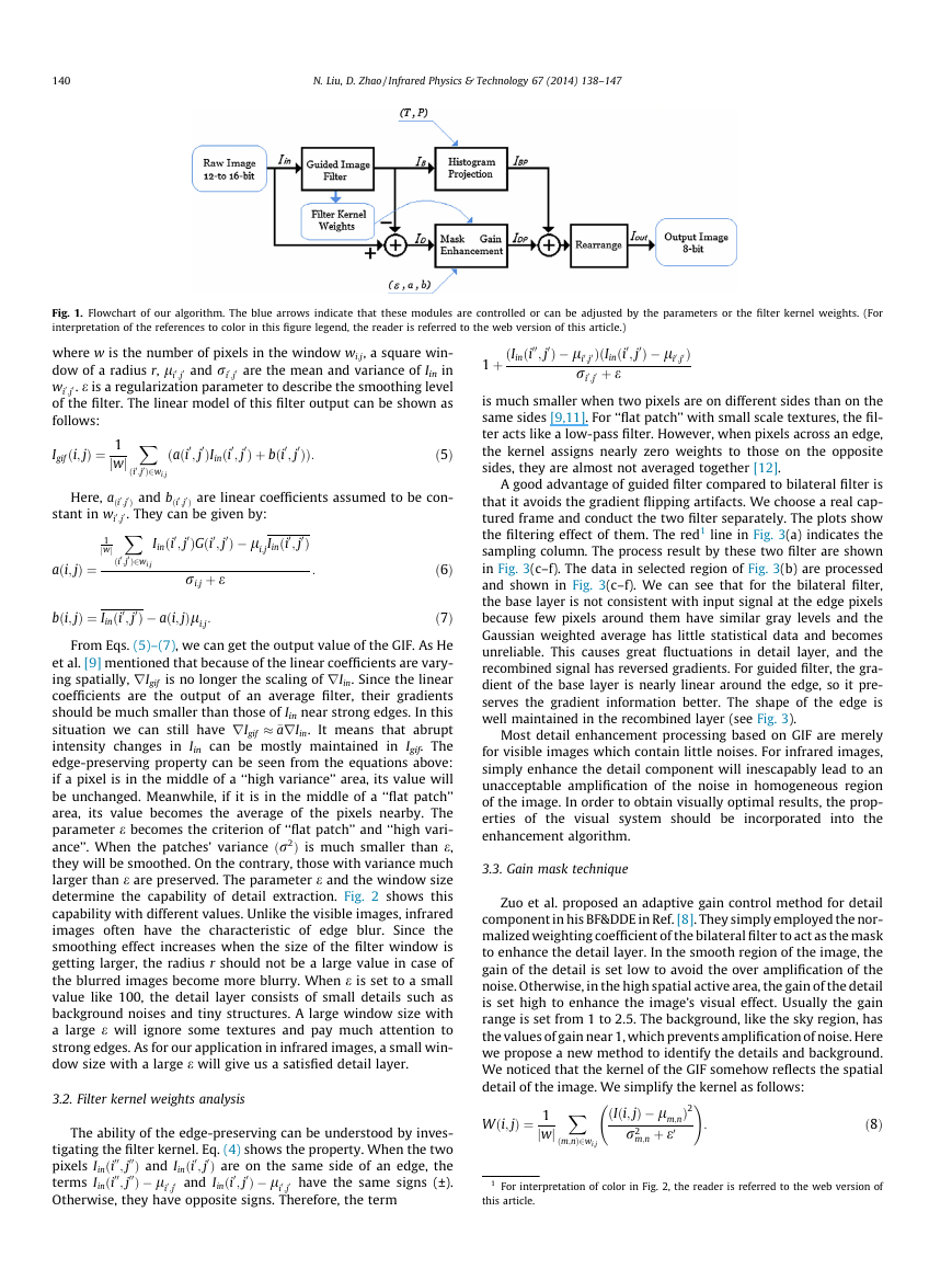
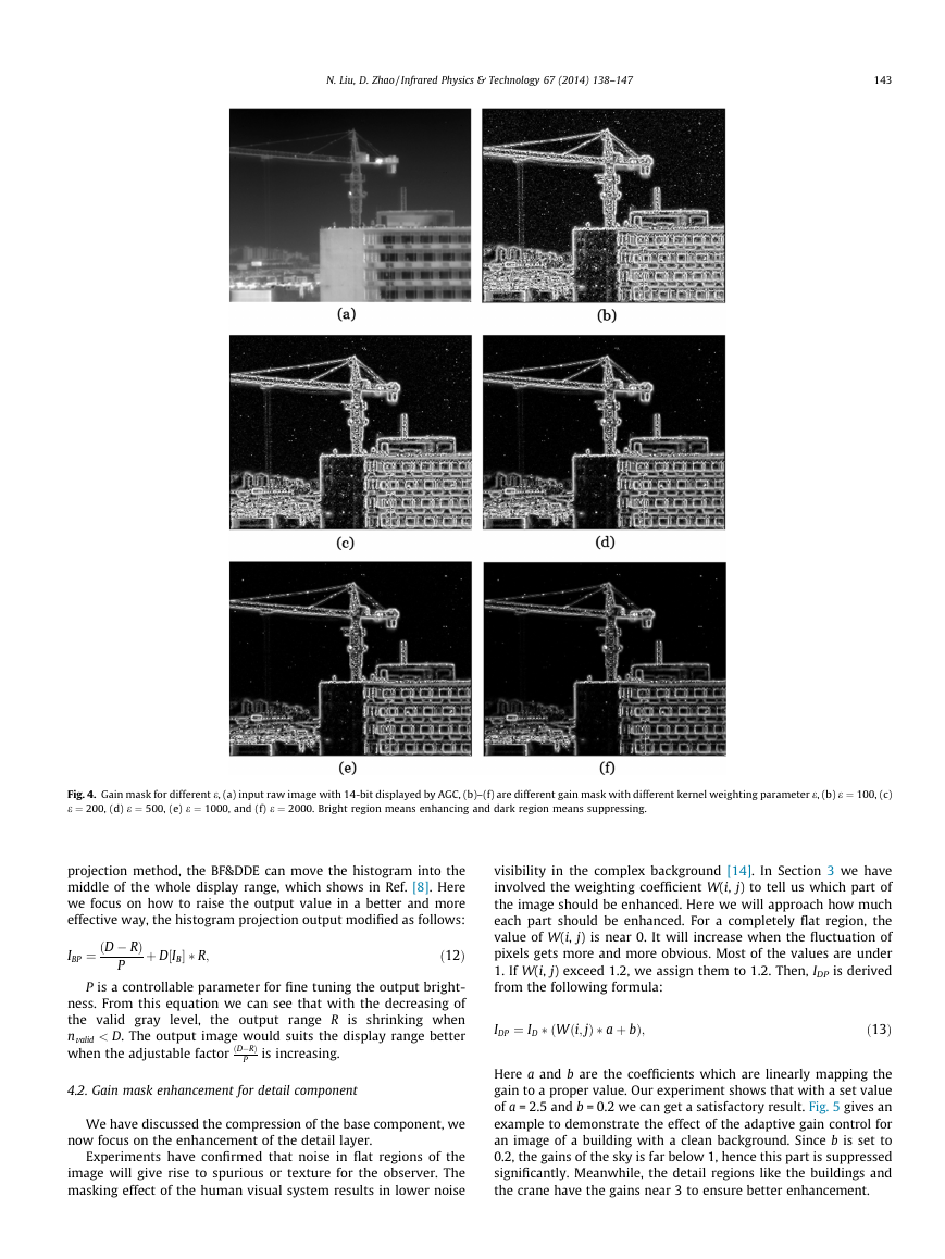
are in the background or not, just like we discussed before. Fig. 4
shows the gain mask of an image with different value of e0. For a
small value of e0, the enhancing region is much bigger and the noise
in background may be identified as details and then enhanced by
mistake. A large parameter shrinks the enhancing region, this
may suppress noise but also details. A proper value of about 500
may be satisfied for our application.
The parameter e0 determines exactly which parts of the image
should be enhanced and which should be restrained. With this tech-
nique we are able to enhance the detail region as much as we need.
Meanwhile, the background like the sky is clean and fresh.
4. Processing of base and detail component
Since the GIF has an excellent effect of separating the images
into two component and involving the gain masking function as
a detail indicator, we then have to deal the two components prop-
erly and recombine them to get the final result.
4.1. Histogram projection for base component
The property of the base component is smoothness and has
wide dynamic range [13]. Hence we can compress it without
DðxÞ ¼
x ¼ 0
;
; other
ð10Þ
HðyÞ
x�1
y¼0
nvalid
worrying about losing details and noise amplification. As Zuo
et al. [8] mentioned in the BF&DDE, in order to guarantee that
the histogram of the image has a quasi-uniform distribution in
its dynamic range, histogram projection is very suitable for this sit-
uation [19,20].
The key point of the histogram projection is that the output
range is the sum of each valid gray level present, regardless of
how many pixels occupy that level. Whether the gray level is
valid depends on the share of the number of pixels in this level.
The histogram of the base layer is binarized by a threshold T. If
the number of pixels in the gray level surpasses T, it will be
identified as valid. Conversely, if the number is less than T, it
will be identified as invalid. Here is the binarized histogram of
IB:
HðxÞ ¼ 0; nx < T
1; nx > T
ð9Þ
�
;
nx is the number of pixels sharing the gray level x. The threshold
T can improve the overall contrast and dramatically change the
global intensity of the display. When T is chosen as 0.1% of the total
number of the pixels, the output of the histogram projection will
have a proper visual effect. The cumulative distribution function
is defined as:
8<
:
P
0;
�
142
N. Liu, D. Zhao / Infrared Physics & Technology 67 (2014) 138–147
Fig. 3. 1-D illustration for detail enhancement for BF and GIF. (a) Input image with selected column; (b) 1-D data of the selected column; (c) BF smoothing effect illustration;
(d) BF detail extraction illustration; (e) GIF smoothing effect illustration; and (f) GIF detail extraction illustration.
Zuo et al. mapped the level x into R�D(x) and change the maxi-
mum range of output image R as:
R ¼ minðnvalid; DÞ;
ð11Þ
where nvalid denotes the total number of the valid gray levels and D
is the dynamic range of a monitor. Here we improve it and make it
more suitable for all possible scenarios. When the dynamic range of
the input is not necessarily higher than the display range, the origi-
nal should not simply be mapped into the output dynamic range D.
When the camera faces a uniform background, like a uniform wall
or the cloudless sky, the number of valid gray level can be a very
small value, perhaps less than 10. In this case, the output of original
histogram projection is mapped into the 8-bit domain, the image
will be distorted and full of noise. For Zuo et al. proposed histogram
�
N. Liu, D. Zhao / Infrared Physics & Technology 67 (2014) 138–147
143
Fig. 4. Gain mask for different e, (a) input raw image with 14-bit displayed by AGC, (b)–(f) are different gain mask with different kernel weighting parameter e, (b) e ¼ 100, (c)
e ¼ 200, (d) e ¼ 500, (e) e ¼ 1000, and (f) e ¼ 2000. Bright region means enhancing and dark region means suppressing.
projection method, the BF&DDE can move the histogram into the
middle of the whole display range, which shows in Ref. [8]. Here
we focus on how to raise the output value in a better and more
effective way, the histogram projection output modified as follows:
IBP ¼ ðD � RÞ
P
þ D IB½
� R;
ð12Þ
P is a controllable parameter for fine tuning the output bright-
ness. From this equation we can see that with the decreasing of
the valid gray level, the output range R is shrinking when
nvalid < D. The output image would suits the display range better
when the adjustable factor ðD�RÞ
is increasing.
P
visibility in the complex background [14]. In Section 3 we have
involved the weighting coefficient W(i, j) to tell us which part of
the image should be enhanced. Here we will approach how much
each part should be enhanced. For a completely flat region, the
value of W(i, j) is near 0. It will increase when the fluctuation of
pixels gets more and more obvious. Most of the values are under
1. If W(i, j) exceed 1.2, we assign them to 1.2. Then, IDP is derived
from the following formula:
IDP ¼ ID � ðWði; jÞ � a þ bÞ;
ð13Þ
4.2. Gain mask enhancement for detail component
We have discussed the compression of the base component, we
now focus on the enhancement of the detail layer.
Experiments have confirmed that noise in flat regions of the
image will give rise to spurious or texture for the observer. The
masking effect of the human visual system results in lower noise
Here a and b are the coefficients which are linearly mapping the
gain to a proper value. Our experiment shows that with a set value
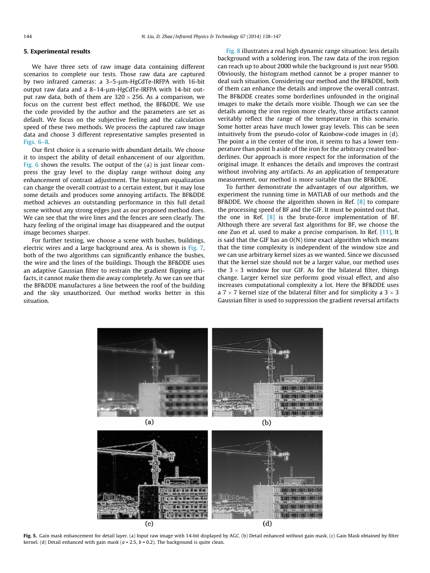
of a = 2.5 and b = 0.2 we can get a satisfactory result. Fig. 5 gives an
example to demonstrate the effect of the adaptive gain control for
an image of a building with a clean background. Since b is set to
0.2, the gains of the sky is far below 1, hence this part is suppressed
significantly. Meanwhile, the detail regions like the buildings and
the crane have the gains near 3 to ensure better enhancement.
�
144
N. Liu, D. Zhao / Infrared Physics & Technology 67 (2014) 138–147
5. Experimental results
We have three sets of raw image data containing different
scenarios to complete our tests. Those raw data are captured
by two infrared cameras: a 3–5-lm-HgCdTe-IRFPA with 16-bit
output raw data and a 8–14-lm-HgCdTe-IRFPA with 14-bit out-
put raw data, both of them are 320 � 256. As a comparison, we
focus on the current best effect method, the BF&DDE. We use
the code provided by the author and the parameters are set as
default. We focus on the subjective feeling and the calculation
speed of these two methods. We process the captured raw image
data and choose 3 different representative samples presented in
Figs. 6–8.
Our first choice is a scenario with abundant details. We choose
it to inspect the ability of detail enhancement of our algorithm.
Fig. 6 shows the results. The output of the (a) is just linear com-
press the gray level to the display range without doing any
enhancement of contrast adjustment. The histogram equalization
can change the overall contrast to a certain extent, but it may lose
some details and produces some annoying artifacts. The BF&DDE
method achieves an outstanding performance in this full detail
scene without any strong edges just as our proposed method does.
We can see that the wire lines and the fences are seen clearly. The
hazy feeling of the original image has disappeared and the output
image becomes sharper.
For further testing, we choose a scene with bushes, buildings,
electric wires and a large background area. As is shown is Fig. 7,
both of the two algorithms can significantly enhance the bushes,
the wire and the lines of the buildings. Though the BF&DDE uses
an adaptive Gaussian filter to restrain the gradient flipping arti-
facts, it cannot make them die away completely. As we can see that
the BF&DDE manufactures a line between the roof of the building
and the sky unauthorized. Our method works better in this
situation.
Fig. 8 illustrates a real high dynamic range situation: less details
background with a soldering iron. The raw data of the iron region
can reach up to about 2000 while the background is just near 9500.
Obviously, the histogram method cannot be a proper manner to
deal such situation. Considering our method and the BF&DDE, both
of them can enhance the details and improve the overall contrast.
The BF&DDE creates some borderlines unfounded in the original
images to make the details more visible. Though we can see the
details among the iron region more clearly, those artifacts cannot
veritably reflect the range of the temperature in this scenario.
Some hotter areas have much lower gray levels. This can be seen
intuitively from the pseudo-color of Rainbow-code images in (d).
The point a in the center of the iron, it seems to has a lower tem-
perature than point b aside of the iron for the arbitrary created bor-
derlines. Our approach is more respect for the information of the
original image. It enhances the details and improves the contrast
without involving any artifacts. As an application of temperature
measurement, our method is more suitable than the BF&DDE.
To further demonstrate the advantages of our algorithm, we
experiment the running time in MATLAB of our methods and the
BF&DDE. We choose the algorithm shown in Ref. [8] to compare
the processing speed of BF and the GIF. It must be pointed out that,
the one in Ref. [8] is the brute-force implementation of BF.
Although there are several fast algorithms for BF, we choose the
one Zuo et al. used to make a precise comparison. In Ref. [11], It
is said that the GIF has an O(N) time exact algorithm which means
that the time complexity is independent of the window size and
we can use arbitrary kernel sizes as we wanted. Since we discussed
that the kernel size should not be a larger value, our method uses
the 3 � 3 window for our GIF. As for the bilateral filter, things
change. Larger kernel size performs good visual effect, and also
increases computational complexity a lot. Here the BF&DDE uses
a 7 � 7 kernel size of the bilateral filter and for simplicity a 3 � 3
Gaussian filter is used to suppression the gradient reversal artifacts
Fig. 5. Gain mask enhancement for detail layer. (a) Input raw image with 14-bit displayed by AGC. (b) Detail enhanced without gain mask. (c) Gain Mask obtained by filter
kernel. (d) Detail enhanced with gain mask (a = 2.5, b = 0.2). The background is quite clean.
�


 2023年江西萍乡中考道德与法治真题及答案.doc
 2012年重庆南川中考生物真题及答案.doc
 2013年江西师范大学地理学综合及文艺理论基础考研真题.doc
 2020年四川甘孜小升初语文真题及答案I卷.doc
 2020年注册岩土工程师专业基础考试真题及答案.doc
 2023-2024学年福建省厦门市九年级上学期数学月考试题及答案.doc
 2021-2022学年辽宁省沈阳市大东区九年级上学期语文期末试题及答案.doc
 2022-2023学年北京东城区初三第一学期物理期末试卷及答案.doc
 2018上半年江西教师资格初中地理学科知识与教学能力真题及答案.doc
 2012年河北国家公务员申论考试真题及答案-省级.doc
 2020-2021学年江苏省扬州市江都区邵樊片九年级上学期数学第一次质量检测试题及答案.doc
 2022下半年黑龙江教师资格证中学综合素质真题及答案.doc