L Y N X F A M I L Y
SM750
Lynx Express 2D Multimedia
Mobile Display Controller
Datasheet
Revision: 1.6
Updated: March 20, 2015
�
Notice
Copyright
Notice
SM750 Datasheet
Silicon Motion, Inc. has made its best efforts to ensure that the information contained in
this document is accurate and reliable. However, the information is subject to change
without notice. No responsibility is assumed by Silicon Motion, Inc. for the use of this
information, nor for infringements of patents or other rights of third parties.
Copyright 2014, Silicon Motion, Inc. All rights reserved. No part of this publication may
be reproduced, photocopied, or transmitted in any form, without the prior written consent
of Silicon Motion, Inc. Silicon Motion, Inc. reserves the right to make changes to the
product specification without reservation and without notice to our users.
Revision No.
Date
Note
0.1
0.2
June 2009
First release
Dec 2009
Second release
0.3
0.4
0.5
1.0
1.1
1.2
1.3
1.4
1.5
1.6
April 2010
Third release
Aug 2011
Dec 2010
May 2011
June 2010
Forth release
Design CD update
-
-
Jun 2012
Jan 2012
Sep 2012
Mar 2014
Mar 2015
Add marking and ordering information
- Update Figure 12, the ending address of the
2D Engine Data Port change to “0x120000”
from “0x150000”
- Update CSR08 register descriptions and
power-on default value
Add MVDD and MVDD2 DC characteristics
in Table 18 and Table 19
Added Standard VGA Register in 2.3.
- Updated Top Marking in 13.2
- Updated Product Ordering Information in 14
Fixed bit names in 2.2, 3.2, 4.1, 6.2, 7, and
-
9.3
Added SM750 0MB Industrial Version IC
Marking in 13.2
Added Part Number SM750GE000000-XX in
14
-
-
- Updated Part Number SM750GX160001-XX
in 14
All rights strictly reserved. No portion of this paper may be reproduced, copied, or
translated into any other form without permission from Silicon Motion, Inc.
Silicon Motion and MMCC are trademarks or registered trademarks of Silicon
Motion, Inc. PCI Express is a trademark of PCI-SIG. All other trademarks are the
property of their respective owners.
2
Copyright
Revision 1.6
�
1.
2.
3.
4.
5.
6.
7.
SM750 Datasheet
Table of Contents
1.3
1.4
General Description ............................................................................................................................. 5
1.1 Overview...................................................................................................................................................... 5
Pins
......................................................................................................................................................... 7
1.2
1.2.1 Pin Descriptions .............................................................................................................................. 7
1.2.2 Package Information ..................................................................................................................... 12
Internal Block Description .......................................................................................................................... 13
1.3.1 PCI Express Interface ................................................................................................................... 13
1.3.2 Display Memory Interface ............................................................................................................. 17
1.3.3 Zoom Video Port ........................................................................................................................... 20
1.3.4 2D Engine ..................................................................................................................................... 20
1.3.5 Video Display Layers .................................................................................................................... 21
1.3.6 LCD Panel .................................................................................................................................... 26
1.3.7 Analog RGB (Analog LCD or CRT) .............................................................................................. 29
1.3.8 GPIO ............................................................................................................................................. 29
1.3.9 Strap Pins ..................................................................................................................................... 30
1.3.10 DMA Controller ............................................................................................................................. 31
1.3.11 Interrupt Controller ........................................................................................................................ 31
1.3.12 Clock Control ................................................................................................................................ 32
1.3.13 Power Management...................................................................................................................... 34
1.3.14 MMIO Space ................................................................................................................................. 35
Standard VGA ........................................................................................................................................... 36
1.4.1 Video BIOS ROM Interface ........................................................................................................... 36
1.4.2 Legacy VGA Support .................................................................................................................... 36
VGA Register ...................................................................................................................................... 37
Functional Overview .................................................................................................................................. 37
2.1
VGA Registers ........................................................................................................................................... 37
2.2
2.2.1 Register Descriptions.................................................................................................................... 37
Standard VGA Register ............................................................................................................................. 38
2.3
2.4
Extended VGA Registers ........................................................................................................................... 66
System Configuration ........................................................................................................................ 70
3.1
Functional Overview .................................................................................................................................. 70
3.2 Register Descriptions ................................................................................................................................ 70
3.2.1 Configuration 1 Register Descriptions .......................................................................................... 71
3.2.2 Power Management Register Descriptions ................................................................................... 90
3.2.3 Configuration 2 Register Descriptions .......................................................................................... 94
PCI Configuration Space ................................................................................................................. 101
4.1 Register Descriptions .............................................................................................................................. 101
Drawing Engine ................................................................................................................................ 115
5.1
Functional Overview ................................................................................................................................ 115
5.2
Programmer’s Model ............................................................................................................................... 115
5.3 Register Descriptions .............................................................................................................................. 116
5.3.1 2D Drawing Engine Registers ..................................................................................................... 118
5.3.2 Color Space Conversion Registers ............................................................................................. 133
Display Controller ............................................................................................................................ 141
6.1
Programmer’s Model ............................................................................................................................... 141
6.2 Register Descriptions .............................................................................................................................. 142
6.2.1 Primary Graphics Control Registers ........................................................................................... 146
6.2.2 Video Control Registers .............................................................................................................. 157
6.2.3 Video Alpha Control Registers .................................................................................................... 165
6.2.4 Primary Display Cursor Control Registers .................................................................................. 171
6.2.5 Alpha Control Registers .............................................................................................................. 174
6.2.6 Secondary Display Graphics Control Registers .......................................................................... 179
6.2.7 Secondary Display Cursor Control Registers ............................................................................. 187
6.2.8 Palette RAM Registers ............................................................................................................... 190
GPIO .................................................................................................................................................. 194
7.1
Functional Overview ................................................................................................................................ 194
Revision 1.6
3
Table of Contents
�
8.
9.
10.
11.
12.
13.
14.
SM750 Datasheet
7.1.1 GPIO Interface ............................................................................................................................ 194
7.2
Programmer’s Model ............................................................................................................................... 195
7.3 Register Descriptions .............................................................................................................................. 196
7.3.1 GPIO Register Descriptions ........................................................................................................ 196
I2C Interface ...................................................................................................................................... 207
8.1
Functional Overview ................................................................................................................................ 207
8.2 Register Descriptions .............................................................................................................................. 208
ZV Port .............................................................................................................................................. 212
Functional Overview ................................................................................................................................ 212
9.1
9.1.1 ZV Port Overview ....................................................................................................................... 212
9.1.2 Video Capture Unit Overview ..................................................................................................... 212
9.2
Programmer’s Model ............................................................................................................................... 213
9.3 Register Descriptions .............................................................................................................................. 214
9.3.1 ZV Port 0 Registers .................................................................................................................... 214
9.3.2 ZV Port 1 Registers .................................................................................................................... 220
DMA Controller (DMAC) .................................................................................................................. 226
10.1 Functional Overview ................................................................................................................................ 226
10.2 Register Descriptions .............................................................................................................................. 228
PWM Specification ........................................................................................................................... 231
11.1 Functional Overview ................................................................................................................................ 231
11.1.1 Delay Counter with Interrupt ....................................................................................................... 231
11.1.2 Internal Timer with Interrupt ........................................................................................................ 231
11.1.3 External Pulse ............................................................................................................................ 231
11.2 Register Descriptions .............................................................................................................................. 232
Specifications ................................................................................................................................... 236
12.1 Soldering Profile ...................................................................................................................................... 236
12.2 DC Characteristics ................................................................................................................................... 237
12.3 AC Timing ................................................................................................................................................ 239
12.3.1 PCI Express Timing .................................................................................................................... 239
12.3.2 Display Controller Timing ............................................................................................................ 239
12.3.3 ZV Port Timing ............................................................................................................................ 241
Packaging Information .................................................................................................................... 242
13.1 Packaging ................................................................................................................................................ 242
13.2 Top Marking ............................................................................................................................................. 243
Product Ordering Information ........................................................................................................ 245
Revision 1.6
4
Table of Contents
�
SM750 Datasheet
1.
1.1
General Description
Overview
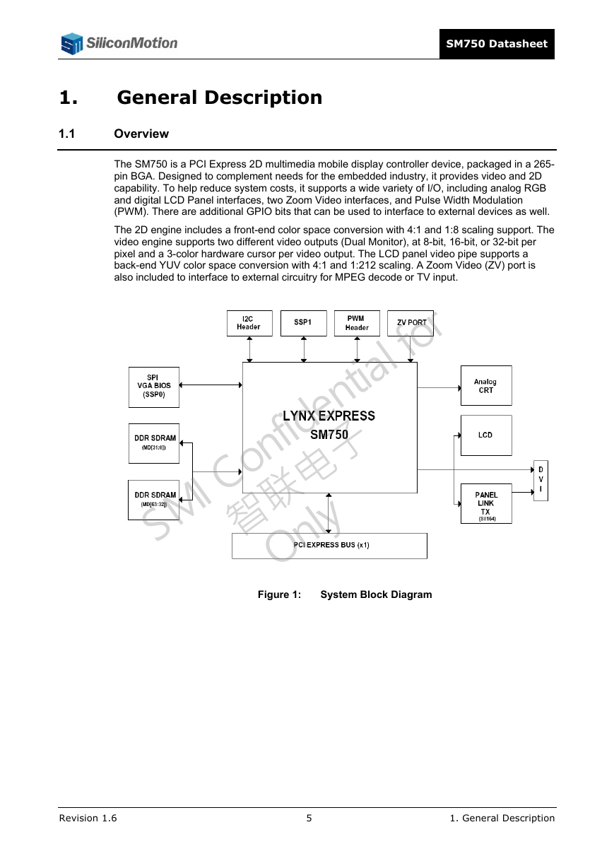
The SM750 is a PCI Express 2D multimedia mobile display controller device, packaged in a 265-
pin BGA. Designed to complement needs for the embedded industry, it provides video and 2D
capability. To help reduce system costs, it supports a wide variety of I/O, including analog RGB
and digital LCD Panel interfaces, two Zoom Video interfaces, and Pulse Width Modulation
(PWM). There are additional GPIO bits that can be used to interface to external devices as well.
The 2D engine includes a front-end color space conversion with 4:1 and 1:8 scaling support. The
video engine supports two different video outputs (Dual Monitor), at 8-bit, 16-bit, or 32-bit per
pixel and a 3-color hardware cursor per video output. The LCD panel video pipe supports a
back-end YUV color space conversion with 4:1 and 1:212 scaling. A Zoom Video (ZV) port is
also included to interface to external circuitry for MPEG decode or TV input.
Figure 1:
System Block Diagram
Revision 1.6
5
1. General Description
�
SM750 Datasheet
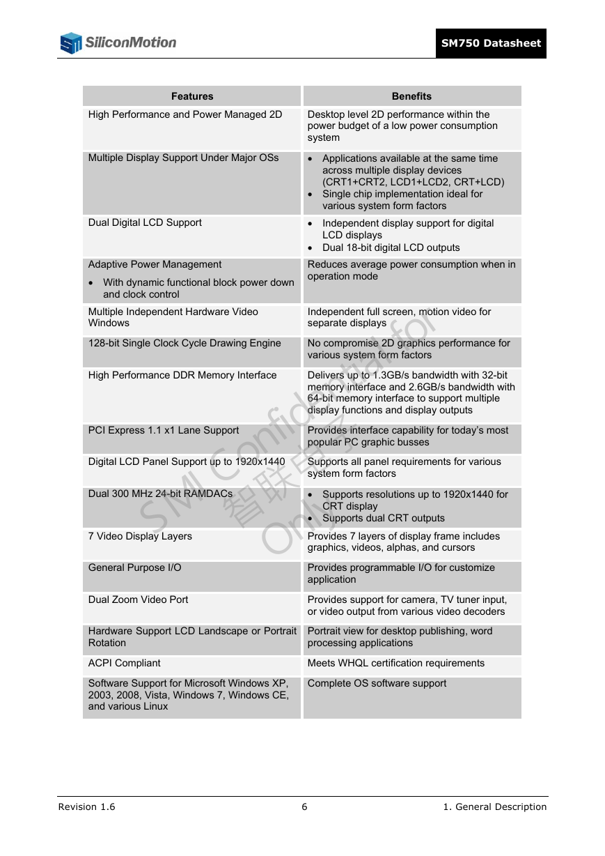
Benefits
Desktop level 2D performance within the
power budget of a low power consumption
system
Applications available at the same time
across multiple display devices
(CRT1+CRT2, LCD1+LCD2, CRT+LCD)
Single chip implementation ideal for
various system form factors
Independent display support for digital
LCD displays
Dual 18-bit digital LCD outputs
Reduces average power consumption when in
operation mode
Features
High Performance and Power Managed 2D
Multiple Display Support Under Major OSs
Dual Digital LCD Support
Adaptive Power Management
With dynamic functional block power down
and clock control
Multiple Independent Hardware Video
Windows
128-bit Single Clock Cycle Drawing Engine
High Performance DDR Memory Interface
Independent full screen, motion video for
separate displays
No compromise 2D graphics performance for
various system form factors
Delivers up to 1.3GB/s bandwidth with 32-bit
memory interface and 2.6GB/s bandwidth with
64-bit memory interface to support multiple
display functions and display outputs
Provides interface capability for today’s most
popular PC graphic busses
Supports all panel requirements for various
system form factors
Supports resolutions up to 1920x1440 for
CRT display
Supports dual CRT outputs
Provides 7 layers of display frame includes
graphics, videos, alphas, and cursors
Provides programmable I/O for customize
application
Provides support for camera, TV tuner input,
or video output from various video decoders
Portrait view for desktop publishing, word
processing applications
Meets WHQL certification requirements
Complete OS software support
PCI Express 1.1 x1 Lane Support
Digital LCD Panel Support up to 1920x1440
Dual 300 MHz 24-bit RAMDACs
7 Video Display Layers
General Purpose I/O
Dual Zoom Video Port
Hardware Support LCD Landscape or Portrait
Rotation
ACPI Compliant
Software Support for Microsoft Windows XP,
2003, 2008, Vista, Windows 7, Windows CE,
and various Linux
Revision 1.6
6
1. General Description
�
1.2
1.2.1
Pins
SM750 Datasheet
Pin Descriptions
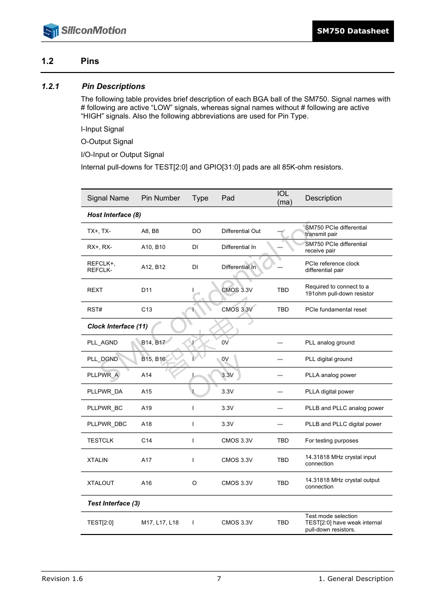
The following table provides brief description of each BGA ball of the SM750. Signal names with
# following are active “LOW” signals, whereas signal names without # following are active
“HIGH” signals. Also the following abbreviations are used for Pin Type.
I -Input Signal
O-Output Signal
I/O -Input or Output Signal
Internal pull-downs for TEST[2:0] and GPIO[31:0] pads are all 85K-ohm resistors.
IOL
(ma)
Description
Signal Name
Pin Number
Type
Pad
Host Interface (8)
DO
DI
DI
―
―
―
A8, B8
A12, B12
A10, B10
Differential In
Differential In
Differential Out
CMOS 3.3V
CMOS 3.3V
B15, B16
B14, B17
TBD
TBD
―
―
D11
C13
I
I
I
0V
3.3V
3.3V
0V
3.3V
I
I
I
I
A14
A15
A19
TX+, TX-
RX+, RX-
REFCLK+,
REFCLK-
REXT
RST#
PLL_AGND
PLL_DGND
PLLPWR_A
PLLPWR_DA
PLLPWR_BC
Clock Interface (11)
SM750 PCIe differential
transmit pair
SM750 PCIe differential
receive pair
PCIe reference clock
differential pair
Required to connect to a
191ohm pull-down resistor
PCIe fundamental reset
PLL analog ground
PLL digital ground
―
PLLA analog power
―
―
―
PLLA digital power
PLLB and PLLC analog power
PLLB and PLLC digital power
3.3V
I
I
I
CMOS 3.3V
TBD
For testing purposes
CMOS 3.3V
TBD
14.31818 MHz crystal input
connection
O
CMOS 3.3V
TBD
14.31818 MHz crystal output
connection
PLLPWR_DBC
A18
TESTCLK
XTALIN
XTALOUT
C14
A17
A16
Test Interface (3)
TEST[2:0]
M17, L17, L18
I
CMOS 3.3V
TBD
Test mode selection
TEST[2:0] have weak internal
pull-down resistors.
7
1. General Description
Revision 1.6
�
SM750 Datasheet
Signal Name
Pin Number
Type
Pad
Memory Interface (104)
IOL
(ma)
Description
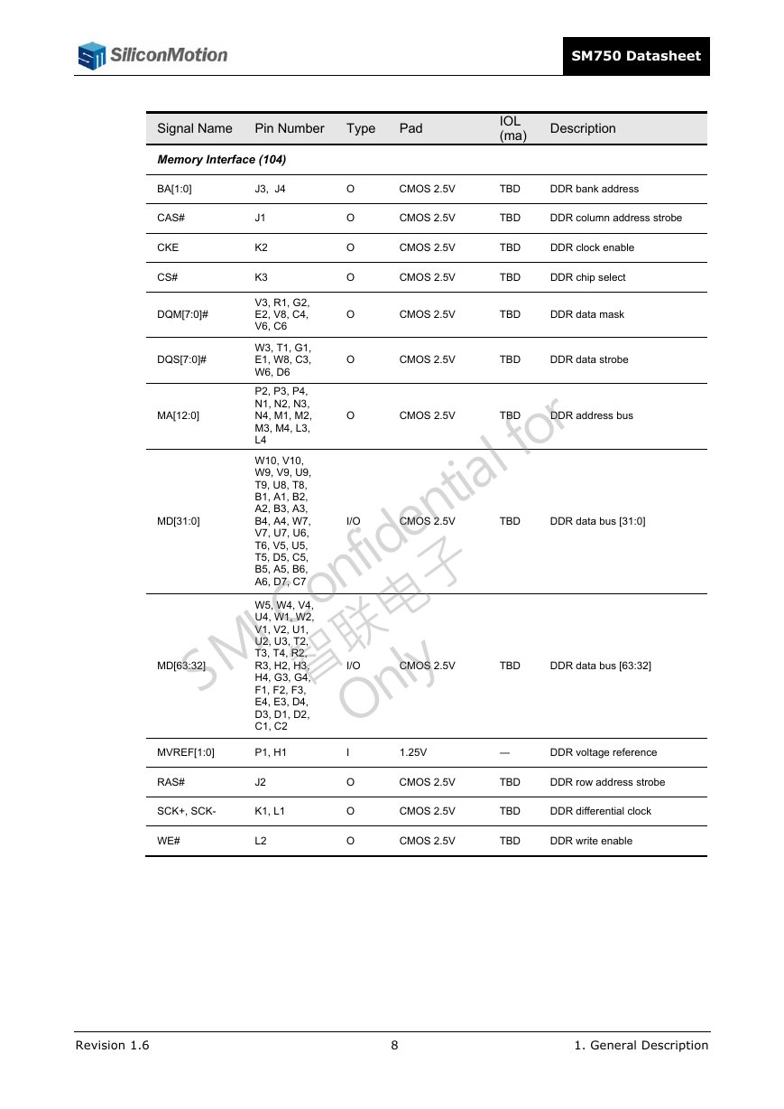
BA[1:0]
CAS#
CKE
CS#
DQM[7:0]#
DQS[7:0]#
MA[12:0]
MD[31:0]
MD[63:32]
J3, J4
J1
K2
K3
V3, R1, G2,
E2, V8, C4,
V6, C6
O
O
O
O
O
O
CMOS 2.5V
TBD
DDR bank address
CMOS 2.5V
CMOS 2.5V
TBD
TBD
DDR column address strobe
DDR clock enable
CMOS 2.5V
TBD
DDR chip select
CMOS 2.5V
TBD
DDR data mask
CMOS 2.5V
TBD
DDR data strobe
O
TBD
DDR address bus
CMOS 2.5V
W3, T1, G1,
E1, W8, C3,
W6, D6
P2, P3, P4,
N1, N2, N3,
N4, M1, M2,
M3, M4, L3,
L4
W10, V10,
W9, V9, U9,
T9, U8, T8,
B1, A1, B2,
A2, B3, A3,
B4, A4, W7,
V7, U7, U6,
T6, V5, U5,
T5, D5, C5,
B5, A5, B6,
A6, D7, C7
CMOS 2.5V
CMOS 2.5V
I/O
I/O
W5, W4, V4,
U4, W1, W2,
V1, V2, U1,
U2, U3, T2,
T3, T4, R2,
R3, H2, H3,
H4, G3, G4,
F1, F2, F3,
E4, E3, D4,
D3, D1, D2,
C1, C2
TBD
DDR data bus [31:0]
TBD
DDR data bus [63:32]
MVREF[1:0]
P1, H1
RAS#
J2
SCK+, SCK-
K1, L1
WE#
L2
I
O
O
O
1.25V
CMOS 2.5V
CMOS 2.5V
―
TBD
TBD
DDR voltage reference
DDR row address strobe
DDR differential clock
CMOS 2.5V
TBD
DDR write enable
Revision 1.6
8
1. General Description
�



 2023年江西萍乡中考道德与法治真题及答案.doc
 2012年重庆南川中考生物真题及答案.doc
 2013年江西师范大学地理学综合及文艺理论基础考研真题.doc
 2020年四川甘孜小升初语文真题及答案I卷.doc
 2020年注册岩土工程师专业基础考试真题及答案.doc
 2023-2024学年福建省厦门市九年级上学期数学月考试题及答案.doc
 2021-2022学年辽宁省沈阳市大东区九年级上学期语文期末试题及答案.doc
 2022-2023学年北京东城区初三第一学期物理期末试卷及答案.doc
 2018上半年江西教师资格初中地理学科知识与教学能力真题及答案.doc
 2012年河北国家公务员申论考试真题及答案-省级.doc
 2020-2021学年江苏省扬州市江都区邵樊片九年级上学期数学第一次质量检测试题及答案.doc
 2022下半年黑龙江教师资格证中学综合素质真题及答案.doc