logo资料库

Silvaco tcad_example.pdf

第1页 / 共516页
第2页 / 共516页
第3页 / 共516页
第4页 / 共516页
第5页 / 共516页
第6页 / 共516页
第7页 / 共516页
第8页 / 共516页
资料共516页,剩余部分请下载后查看
TCAD Tutorial and Examples Volume 1
Introduction
Examples Index:
List of Figures:
Chapter 1:
MOS1: MOS Application Examples
1.1. MOS1: MOS Application Examples
1.1.1. mos1ex01.in: NMOS: Id/Vgs and Threshold Voltage Extraction
1.1.2. mos1ex02.in: NMOS: Family of Id/Vds Curves
1.1.3. mos1ex03.in: NMOS: Sub-Threshold Slope Extraction
1.1.4. mos1ex04.in: NMOS: DIBL Extraction
1.1.5. mos1ex05.in: NMOS: Body Effect Extraction
1.1.6. mos1ex06.in: NMOS: Substrate and Gate Current Extraction
1.1.7. mos1ex07.in: NMOS: Breakdown Voltage Extraction
1.1.8. mos1ex08.in: PMOS: Id/Vgs and Threshold Voltage Extraction
1.1.9. mos1ex09.in: PMOS: Family of Id/Vds Curves
1.1.10. mos1ex10.in: PMOS: Sub-Threshold Slope Extraction
1.1.11. mos1ex11.in: PMOS: DIBL Extraction
1.1.12. mos1ex12.in: PMOS: Body Effect Extraction
1.1.13. mos1ex13.in: PMOS: Substrate and Gate Current Extraction
1.1.14. mos1ex14.in: PMOS: Breakdown Voltage Extraction
1.1.15. mos1ex15.in: NMOS: Gate Length Scaling
Chapter 2:
MOS2: Advanced MOS Applications Examples
2.1. MOS2: Advanced MOS Application Examples
2.1.1. mos2ex01.in: Circuit Analysis of NMOS Inverters
2.1.2. mos2ex02.in: Hot Electron Reliability
2.1.3. mos2ex03.in: Gate Turn-on Transient
2.1.4. mos2ex04.in: 3D Width Effect Simulation
2.1.5. mos2ex05.in: Comparison of Id/Vds using EB and NEB models
2.1.6. mos2ex06.in: BSIM3 SPICE Model Extraction (Salicide process)
2.1.7. mos2ex07.in: NMOS Snapback
2.1.8. mos2ex08.in: NMOS Second Breakdown Simulation
2.1.9. mos2ex09.in: Drain/Gate Overlap Capacitance
2.1.10. mos2ex10.in: 2D NMOS simulation from 1D SSUPREM3 Doping
2.1.11. mos2ex11.in: Breakdown Voltage using Ionization Integrals
2.1.12. mos2ex12.in: SiGe PMOS Process and Device Simulation
2.1.13. mos2ex13.in: SiGe PMOS Id/Vds with NEB Model
2.1.14. mos2ex14.in: Comparison of CVT, SHIRAHATA and WATT Mobility Models
2.1.15. mos2ex15.in : Effect of Poly Depletion on C-V curves
2.1.16. mos2ex16.in : Effect of Poly Doping on Threshold Voltage
Chapter 3:
BJT: Bipolar Application Examples
3.1. BJT: Bipolar Application Examples
3.1.1. bjtex01.in: NPN Gummel Plot and fT Extraction
3.1.2. bjtex02.in: 3D Bipolar Simulation
3.1.3. bjtex03.in: Analysis of NPN Device with 2 Base Contacts
3.1.4. bjtex04.in: NPN - Gummel Plot and Ic/Vce Characterization
3.1.5. bjtex05.in: NPN - BVCEO Breakdown Voltage
3.1.6. bjtex06.in: NPN - AC Frequency Response
3.1.7. bjtex07.in: 3D NPN Transient Response
3.1.8. bjtex08.in: PNP Gummel Plot and Ic/Vce Characteristic
3.1.9. bjtex09.in: Emitter-Coupled Logic Element Simulation
3.1.10. bjtex10.in: SSUPREM3/ATLAS Simulation of an NPN BJT
3.1.11. bjtex11.in: NPN - Gummel plot in 2D and 3D
Chapter 4:
DIODE: Diode Application Examples
4.1. DIODE: Diode Application Examples
4.1.1. diodeex01.in: Schottky Diode Forward Characteristic
4.1.2. diodeex02.in: Breakdown Simulation with EB and NEB Models
4.1.3. diodeex03.in: Breakdown Simulation with the Curve Tracer
4.1.4. diodeex04.in: Silicon Carbide Diode Characteristics
4.1.5. diodeex05.in: Zener Diode Breakdown
4.1.6. diodeex06.in: 3D Diode Characteristic
4.1.7. diodeex07.in: Gunn Diode
4.1.8. diodeex08.in : 3D Diode Using Lifetime Killing
4.1.9. diodeex09.in : Temperature Ramping – Effect on Leakage
Chapter 5:
SOI: SOI Application Examples
5.1. SOI: SOI Application Examples
5.1.1. soiex01.in: Partially Depleted SOI - Vt and Subthreshold Slope
5.1.2. soiex02.in: Fully Depleted SOI - Vt and Subthreshold Slope
5.1.3. soiex03.in: Partially vs Fully Depleted SOI - Leakage Current Analysis
5.1.4. soiex04.in: The “Kink” Effect in Partially Depleted SOI MOSFETs
5.1.5. soiex05.in: Negative Transconductance - Effect of Lattice Heating
5.1.6. soiex06.in: Breakdown in SOI MOSFETs - Effect of Lattice Heating
5.1.7. soiex07.in: 3D Device Simulation - Effect of a Body Contact
5.1.8. soiex08.in: Modeling for Deep Submicron - Process to Device
5.1.9. soiex09.in : 3D Device Simulation - Effect of Lattice Heating
Chapter 6:
EPROM: EPROM Application Examples
6.1. EPROM: Application Examples
6.1.1. eprmex01.in: Flash EEPROM Programming and Erasing
6.1.2. eprmex02.in: 3D Flash EPROM Programming
6.1.3. eprmex03.in: Controlling the Capacitative Coupling
6.1.4. eprmex04.in: Hot Carrier Injection and Ionization
Chapter 7:
LATCHUP: CMOS Latchup Application Examples
7.1. LATCHUP: CMOS Latchup Application Examples
7.1.1. latchex01.in: Transient Simulation of CMOS Latch-Up
7.1.2. latchex02.in: CMOS Latch-Up By Positive Voltage on Vdd
7.1.3. latchex03.in: CMOS Latch-Up By Negative Voltage on Vss
7.1.4. latchex04.in: Transient 3D CMOS Latch-Up
Chapter 8:
ESD: ESD Application Examples
8.1. ESD: ESD Application Examples
8.1.1. esdex01.in: Human Body Model in a Diode
8.1.2. esdex02.in: Charge Device Model in a Diode
8.1.3. esdex03.in: Human Body Model in a MOSFET
8.1.4. esdex04.in: HBM in a MOSFET with Energy Balance Models
8.1.5. esdex05.in: Second Breakdown of a MOSFET
Chapter 9:
POWER: Power Device Application Examples
9.1. POWER: Power Device Application Examples
9.1.1. powerex01.in: Reverse Recovery of a Power Diode
9.1.2. powerex02.in: Vertical DMOS Turn-on Characteristics
9.1.3. powerex03.in: IGBT Transient Latch-up with Lattice Heating
9.1.4. powerex04.in: IGBT Ic/Vce Characteristics
9.1.5. powerex05.in: Guard Ring Breakdown Analysis
9.1.6. powerex06.in: GTO Turn-off Transient
9.1.7. powerex07.in: LDMOS Breakdown
9.1.8. powerex08.in: LDMOS Breakdown using Ionization Integrals
9.1.9. powerex09.in : Anisotropic Mobility Characteristics of a SiC T-MOSFET
9.1.10. powerex10.in : Anisotropic Mobility Characteristics of a SiC DMOS Device
9.1.11. powerex11.in : Vertical DMOS Gate Charging Simulation
Chapter 10:
ISOLATION: ISO Application Examples
10.1. ISOLATION : ISOLATION Applications Examples
10.1.1 isolationex01.in : Local Oxidation Isolation Punchthrough
10.1.2 {subsection} isolationex02.in : Trench Isolation Punchthrough
TCAD Tutorial and Examples Volume I SILVACO International 4701 Patrick Henry Drive, Bldg. 1 Santa Clara, CA 94054 Telephone: (408) 567-1000 January 1999 FAX: (408) 496-6080 E-Mail: support@silvaco.com Internet: http://www.SILVACO.com Edition Two www.cadfamily.com EMail:cadserv21@hotmail.com The document is for study only,if tort to your rights,please inform us,we will delete
TCAD Tutorial and Examples Manual Volume I Copyright 1999 SILVACO International 4701 Patrick Henry Drive, Bldg. 1 Santa Clara, CA 95054 Phone: (408) 567-1000 FAX: (408) 496-6080 E-Mail: support@silvaco.com Internet: http://www.SILVACO.com www.cadfamily.com EMail:cadserv21@hotmail.com The document is for study only,if tort to your rights,please inform us,we will delete
Notice The information contained in this document is subject to change without notice. SILVACO International MAKES NO WARRANTY OF ANY KIND WITH REGARD TO THIS MATERIAL, INCLUDING, BUT NOT LIMITED TO, THE IMPLIED WARRANTY OF FIT- NESS FOR A PARTICULAR PURPOSE. SILVACO International Inc. shall not be liable for errors contained herein or for incidental or con- sequential damages in connection with the furnishing, performance, or use of this material. This document contains proprietary information, which is protected by copyright. All rights are re- served. No part of this document may be photocopied, reproduced, or translated into another lan- guage without the prior written consent of SILVACO International. SIMULATION STANDARD, TCADDRIVENCAD, VIRTUAL WAFER FAB, ANALOG ALLIANCE, LEGACY, ATHENA, ATLAS, FAST ATLAS, ODIN, VYPER, CRUSADE, RESILIENCE, DISCOVERY, CE- LEBRITY, PRODUCTION TOOLS, AUTOMATION TOOLS, INTERACTIVE TOOLS, TONYPLOT, DECKBUILD, DEVEDIT, INTERPRETER, ATHENA INTERPRETER, ATLAS INTERPRETER, CIRCUIT OPTIMIZER, MASK- VIEWS, PSTATS, SSUPREM3, SSUPREM4, ELITE, OPTOLITH, FLASH, SILICIDES, SPDB, CMP, MC DE- POSIT, MC IMPLANT, PROCESS ADAPTIVE MESHING, S-PISCES, BLAZE, DEVICE 3D, INTERCONNECT3D, BLAZE3D, GIGA3D, MIZEDMODE3D, TFT, LUMINOUS, GIGA, MIZEDMODE, ESD, LASER, FASTBLAZE, FASTMIXEDMODE, FASTGIGA, FASTNOISE, MOCASIM, UTMOST, UTOMST II, UTMOST III, UT- MOST IV, PROMOST, SPAYN, SMARTSPICE, MIXSIM, TWISTER, FASTSPICE, SMARTLIB, SDDL, EX- ACT, CLEVER, STELLAR, HIPEX, LISA, SCHOLAR, SIREN, ESCORT, STARLET, EXPERT, SAVAGE, SCOUT, GUARDIAN, and ENVOY are trademarks of SILVACO INTERNATIONAL. All other trademarks mentioned in this manual are the property of their respective owners. ©1990, 1991, 1992, 1993, 1994, 1995, 1996, 1997, 1998, 1999 by SILVACO International, Inc. SILVACO International iii www.cadfamily.com EMail:cadserv21@hotmail.com The document is for study only,if tort to your rights,please inform us,we will delete
Reader Comment Sheet We welcome your evaluation of this manual. Your comments and suggestions help us to improve our publications. If you have any responses to the questions below, please let us know. Write your observations down and send complaints, bug reports, suggestions or comments to the e-mail ad- dress listed below. • Is this manual technically accurate? Are the concepts and wording easy to understand? Is the size of this manual convenient for you? Is the manual’s arrangement convenient for you? Do you consider this manual to be easily readable? Please add any additional relevant comments. Please FAX your comments to SILVACO International Attention Technical Publications 1701 Patrick Henry Drive, Building 1 Santa Clara, CA 95054 at (408) 496-6080. or Send e-mail to us at: support@silvaco.com or Browse our Web Page at http://www.SILVACO.com iv SILVACO International www.cadfamily.com EMail:cadserv21@hotmail.com The document is for study only,if tort to your rights,please inform us,we will delete
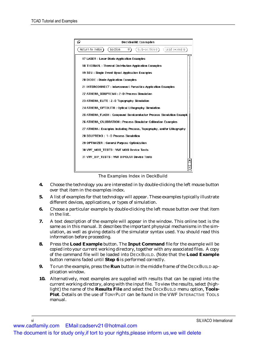
Introduction Intended Audience The information in this manual is based on the following assumptions: The reader is familiar with the basic terminology of semiconductor processing and semi- conductor device operation, and The reader understands the basic operations of the computer hardware and operation systems being used. Introduction This manual is intended as an additional guide to the use of Silvaco’s process and device simulators. It contains descriptions of all the standard examples that demonstrate the use of SSUPREM3, ATHENA, ATLAS, and the VWF INTERACTIVE TOOLS manuals. Users should consult the relevant “User’s Manual” for a full description of the models and syntax of each program. Included on your distribution media are more than five hundred (500) Standard Examples that demonstrate the way that the simulators are used to model many different technologies. The exam- ples are instructional and it is strongly recommended that new users apply these examples as a starting point for creating their own simulations. One of the first things you should learn is how to access, load, and run these examples. Accessing the Examples The examples are accessed from the menu system in DECKBUILD. To select and load an example: 1. 2. Start DECKBUILD as described in the VWF INTERACTIVE TOOLS MANUAL. Pull down the MainControl menu using the right hand mouse button. There are op- tions on this menu for MainControl, Optimizer, Examples, Help, etc. Select Examples. An index will appear in a DeckBuild: Examples window (see be- low). The examples are divided by technology or technology group. The most common technolo- gies are clear (e.g., MOS, BJT) while others are grouped with similar devices (e.g., IGBT and LDMOS are under POWER, and solar cell and photodiode are under OPTOELECTRONICS). 3. SILVACO International www.cadfamily.com EMail:cadserv21@hotmail.com The document is for study only,if tort to your rights,please inform us,we will delete v
TCAD Tutorial and Examples The Examples Index in DeckBuild 4. 5. 6. 7. 8. 9. Choose the technology you are interested in by double-clicking the left mouse button over that item in the examples index. A list of examples for that technology will appear. These examples typically illustrate different devices, applications, or types of simulation. Choose a particular example by double-clicking the left mouse button over that item in the list. A text description of the example will appear in the window. This online text is the same as in this manual. It describes the important physyical mechanisms in the sim- ulation, as well as giving details of the simulator syntax used. You should read this information before proceeding. Press the Load Example button. The Input Command file for the example will be copied into your current working directory, together with any associated files. A copy of the command file will be loaded into DECKBUILD. (Note that the Load Example button remains faded until Step 6 is performed correctly. To run the example, press the Run button in the middle frame of the DECKBUILD ap- plication window. 10. Alternatively, most examples are supplied with results that can be copied into the current working directory, along with the input file. To view the results, select (high- light) the name of the Results File and select the DECKBUILD menu option, Tools- Plot. Details on the use of TONYPLOT can be found in the VWF INTERACTIVE TOOLS manual. vi SILVACO International www.cadfamily.com EMail:cadserv21@hotmail.com The document is for study only,if tort to your rights,please inform us,we will delete
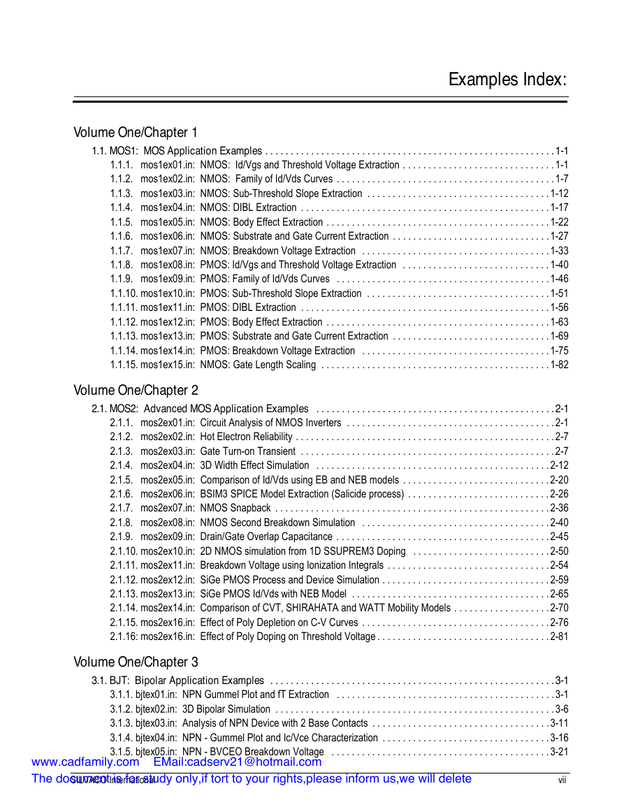
Examples Index: Volume One/Chapter 1 1.1. MOS1: MOS Application Examples . . . . . . . . . . . . . . . . . . . . . . . . . . . . . . . . . . . . . . . . . . . . . . . . . . . . . . . . . 1-1 1.1.1. mos1ex01.in: NMOS: Id/Vgs and Threshold Voltage Extraction . . . . . . . . . . . . . . . . . . . . . . . . . . . . . . 1-1 1.1.2. mos1ex02.in: NMOS: Family of Id/Vds Curves . . . . . . . . . . . . . . . . . . . . . . . . . . . . . . . . . . . . . . . . . . . 1-7 1.1.3. mos1ex03.in: NMOS: Sub-Threshold Slope Extraction . . . . . . . . . . . . . . . . . . . . . . . . . . . . . . . . . . . . 1-12 1.1.4. mos1ex04.in: NMOS: DIBL Extraction . . . . . . . . . . . . . . . . . . . . . . . . . . . . . . . . . . . . . . . . . . . . . . . . . 1-17 1.1.5. mos1ex05.in: NMOS: Body Effect Extraction . . . . . . . . . . . . . . . . . . . . . . . . . . . . . . . . . . . . . . . . . . . . 1-22 1.1.6. mos1ex06.in: NMOS: Substrate and Gate Current Extraction . . . . . . . . . . . . . . . . . . . . . . . . . . . . . . . 1-27 1.1.7. mos1ex07.in: NMOS: Breakdown Voltage Extraction . . . . . . . . . . . . . . . . . . . . . . . . . . . . . . . . . . . . . 1-33 1.1.8. mos1ex08.in: PMOS: Id/Vgs and Threshold Voltage Extraction . . . . . . . . . . . . . . . . . . . . . . . . . . . . . 1-40 1.1.9. mos1ex09.in: PMOS: Family of Id/Vds Curves . . . . . . . . . . . . . . . . . . . . . . . . . . . . . . . . . . . . . . . . . . 1-46 1.1.10. mos1ex10.in: PMOS: Sub-Threshold Slope Extraction . . . . . . . . . . . . . . . . . . . . . . . . . . . . . . . . . . . . 1-51 1.1.11. mos1ex11.in: PMOS: DIBL Extraction . . . . . . . . . . . . . . . . . . . . . . . . . . . . . . . . . . . . . . . . . . . . . . . . . 1-56 1.1.12. mos1ex12.in: PMOS: Body Effect Extraction . . . . . . . . . . . . . . . . . . . . . . . . . . . . . . . . . . . . . . . . . . . . 1-63 1.1.13. mos1ex13.in: PMOS: Substrate and Gate Current Extraction . . . . . . . . . . . . . . . . . . . . . . . . . . . . . . . 1-69 1.1.14. mos1ex14.in: PMOS: Breakdown Voltage Extraction . . . . . . . . . . . . . . . . . . . . . . . . . . . . . . . . . . . . . 1-75 1.1.15. mos1ex15.in: NMOS: Gate Length Scaling . . . . . . . . . . . . . . . . . . . . . . . . . . . . . . . . . . . . . . . . . . . . . 1-82 Volume One/Chapter 2 2.1. MOS2: Advanced MOS Application Examples . . . . . . . . . . . . . . . . . . . . . . . . . . . . . . . . . . . . . . . . . . . . . . . 2-1 2.1.1. mos2ex01.in: Circuit Analysis of NMOS Inverters . . . . . . . . . . . . . . . . . . . . . . . . . . . . . . . . . . . . . . . . . 2-1 2.1.2. mos2ex02.in: Hot Electron Reliability . . . . . . . . . . . . . . . . . . . . . . . . . . . . . . . . . . . . . . . . . . . . . . . . . . . 2-7 2.1.3. mos2ex03.in: Gate Turn-on Transient . . . . . . . . . . . . . . . . . . . . . . . . . . . . . . . . . . . . . . . . . . . . . . . . . . 2-7 2.1.4. mos2ex04.in: 3D Width Effect Simulation . . . . . . . . . . . . . . . . . . . . . . . . . . . . . . . . . . . . . . . . . . . . . . 2-12 2.1.5. mos2ex05.in: Comparison of Id/Vds using EB and NEB models . . . . . . . . . . . . . . . . . . . . . . . . . . . . . 2-20 2.1.6. mos2ex06.in: BSIM3 SPICE Model Extraction (Salicide process) . . . . . . . . . . . . . . . . . . . . . . . . . . . . 2-26 2.1.7. mos2ex07.in: NMOS Snapback . . . . . . . . . . . . . . . . . . . . . . . . . . . . . . . . . . . . . . . . . . . . . . . . . . . . . . 2-36 2.1.8. mos2ex08.in: NMOS Second Breakdown Simulation . . . . . . . . . . . . . . . . . . . . . . . . . . . . . . . . . . . . . 2-40 2.1.9. mos2ex09.in: Drain/Gate Overlap Capacitance . . . . . . . . . . . . . . . . . . . . . . . . . . . . . . . . . . . . . . . . . . 2-45 2.1.10. mos2ex10.in: 2D NMOS simulation from 1D SSUPREM3 Doping . . . . . . . . . . . . . . . . . . . . . . . . . . . 2-50 2.1.11. mos2ex11.in: Breakdown Voltage using Ionization Integrals . . . . . . . . . . . . . . . . . . . . . . . . . . . . . . . . 2-54 2.1.12. mos2ex12.in: SiGe PMOS Process and Device Simulation . . . . . . . . . . . . . . . . . . . . . . . . . . . . . . . . . 2-59 2.1.13. mos2ex13.in: SiGe PMOS Id/Vds with NEB Model . . . . . . . . . . . . . . . . . . . . . . . . . . . . . . . . . . . . . . . 2-65 2.1.14. mos2ex14.in: Comparison of CVT, SHIRAHATA and WATT Mobility Models . . . . . . . . . . . . . . . . . . . 2-70 2.1.15. mos2ex16.in: Effect of Poly Depletion on C-V Curves . . . . . . . . . . . . . . . . . . . . . . . . . . . . . . . . . . . . . 2-76 2.1.16: mos2ex16.in: Effect of Poly Doping on Threshold Voltage . . . . . . . . . . . . . . . . . . . . . . . . . . . . . . . . . . 2-81 Volume One/Chapter 3 3.1. BJT: Bipolar Application Examples . . . . . . . . . . . . . . . . . . . . . . . . . . . . . . . . . . . . . . . . . . . . . . . . . . . . . . . . 3-1 3.1.1. bjtex01.in: NPN Gummel Plot and fT Extraction . . . . . . . . . . . . . . . . . . . . . . . . . . . . . . . . . . . . . . . . . . . 3-1 3.1.2. bjtex02.in: 3D Bipolar Simulation . . . . . . . . . . . . . . . . . . . . . . . . . . . . . . . . . . . . . . . . . . . . . . . . . . . . . . . 3-6 3.1.3. bjtex03.in: Analysis of NPN Device with 2 Base Contacts . . . . . . . . . . . . . . . . . . . . . . . . . . . . . . . . . . . 3-11 3.1.4. bjtex04.in: NPN - Gummel Plot and Ic/Vce Characterization . . . . . . . . . . . . . . . . . . . . . . . . . . . . . . . . . 3-16 3.1.5. bjtex05.in: NPN - BVCEO Breakdown Voltage . . . . . . . . . . . . . . . . . . . . . . . . . . . . . . . . . . . . . . . . . . . 3-21 www.cadfamily.com EMail:cadserv21@hotmail.com The document is for study only,if tort to your rights,please inform us,we will delete SILVACO International vii
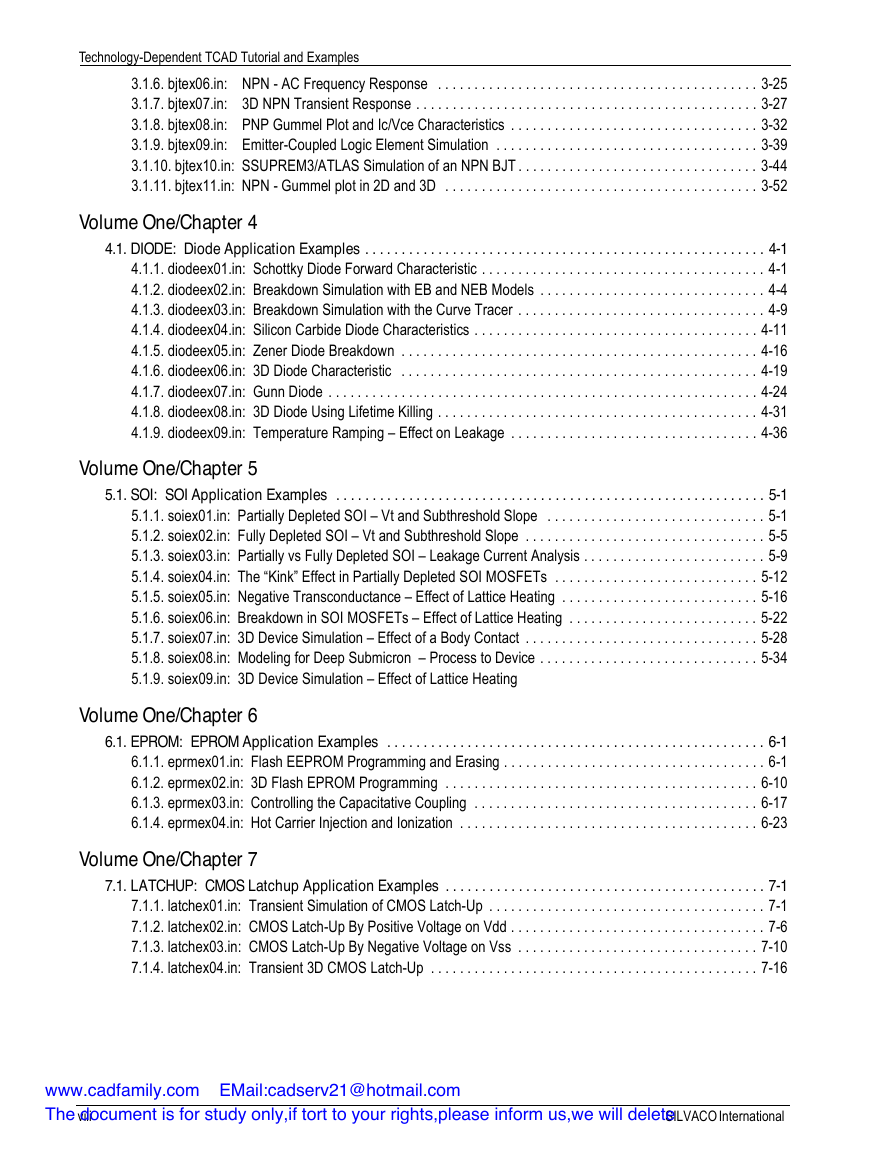
Technology-Dependent TCAD Tutorial and Examples 3.1.6. bjtex06.in: NPN - AC Frequency Response . . . . . . . . . . . . . . . . . . . . . . . . . . . . . . . . . . . . . . . . . . . . 3-25 3.1.7. bjtex07.in: 3D NPN Transient Response . . . . . . . . . . . . . . . . . . . . . . . . . . . . . . . . . . . . . . . . . . . . . . . 3-27 3.1.8. bjtex08.in: PNP Gummel Plot and Ic/Vce Characteristics . . . . . . . . . . . . . . . . . . . . . . . . . . . . . . . . . . 3-32 3.1.9. bjtex09.in: Emitter-Coupled Logic Element Simulation . . . . . . . . . . . . . . . . . . . . . . . . . . . . . . . . . . . . 3-39 3.1.10. bjtex10.in: SSUPREM3/ATLAS Simulation of an NPN BJT . . . . . . . . . . . . . . . . . . . . . . . . . . . . . . . . . 3-44 3.1.11. bjtex11.in: NPN - Gummel plot in 2D and 3D . . . . . . . . . . . . . . . . . . . . . . . . . . . . . . . . . . . . . . . . . . . 3-52 Volume One/Chapter 4 4.1. DIODE: Diode Application Examples . . . . . . . . . . . . . . . . . . . . . . . . . . . . . . . . . . . . . . . . . . . . . . . . . . . . . . . 4-1 4.1.1. diodeex01.in: Schottky Diode Forward Characteristic . . . . . . . . . . . . . . . . . . . . . . . . . . . . . . . . . . . . . . . 4-1 4.1.2. diodeex02.in: Breakdown Simulation with EB and NEB Models . . . . . . . . . . . . . . . . . . . . . . . . . . . . . . . 4-4 4.1.3. diodeex03.in: Breakdown Simulation with the Curve Tracer . . . . . . . . . . . . . . . . . . . . . . . . . . . . . . . . . . 4-9 4.1.4. diodeex04.in: Silicon Carbide Diode Characteristics . . . . . . . . . . . . . . . . . . . . . . . . . . . . . . . . . . . . . . . 4-11 4.1.5. diodeex05.in: Zener Diode Breakdown . . . . . . . . . . . . . . . . . . . . . . . . . . . . . . . . . . . . . . . . . . . . . . . . . 4-16 4.1.6. diodeex06.in: 3D Diode Characteristic . . . . . . . . . . . . . . . . . . . . . . . . . . . . . . . . . . . . . . . . . . . . . . . . . 4-19 4.1.7. diodeex07.in: Gunn Diode . . . . . . . . . . . . . . . . . . . . . . . . . . . . . . . . . . . . . . . . . . . . . . . . . . . . . . . . . . . 4-24 4.1.8. diodeex08.in: 3D Diode Using Lifetime Killing . . . . . . . . . . . . . . . . . . . . . . . . . . . . . . . . . . . . . . . . . . . . 4-31 4.1.9. diodeex09.in: Temperature Ramping – Effect on Leakage . . . . . . . . . . . . . . . . . . . . . . . . . . . . . . . . . . 4-36 Volume One/Chapter 5 5.1. SOI: SOI Application Examples . . . . . . . . . . . . . . . . . . . . . . . . . . . . . . . . . . . . . . . . . . . . . . . . . . . . . . . . . . . 5-1 5.1.1. soiex01.in: Partially Depleted SOI – Vt and Subthreshold Slope . . . . . . . . . . . . . . . . . . . . . . . . . . . . . . 5-1 5.1.2. soiex02.in: Fully Depleted SOI – Vt and Subthreshold Slope . . . . . . . . . . . . . . . . . . . . . . . . . . . . . . . . . 5-5 5.1.3. soiex03.in: Partially vs Fully Depleted SOI – Leakage Current Analysis . . . . . . . . . . . . . . . . . . . . . . . . . 5-9 5.1.4. soiex04.in: The “Kink” Effect in Partially Depleted SOI MOSFETs . . . . . . . . . . . . . . . . . . . . . . . . . . . . 5-12 5.1.5. soiex05.in: Negative Transconductance – Effect of Lattice Heating . . . . . . . . . . . . . . . . . . . . . . . . . . . 5-16 5.1.6. soiex06.in: Breakdown in SOI MOSFETs – Effect of Lattice Heating . . . . . . . . . . . . . . . . . . . . . . . . . . 5-22 5.1.7. soiex07.in: 3D Device Simulation – Effect of a Body Contact . . . . . . . . . . . . . . . . . . . . . . . . . . . . . . . . 5-28 5.1.8. soiex08.in: Modeling for Deep Submicron – Process to Device . . . . . . . . . . . . . . . . . . . . . . . . . . . . . . 5-34 5.1.9. soiex09.in: 3D Device Simulation – Effect of Lattice Heating Volume One/Chapter 6 6.1. EPROM: EPROM Application Examples . . . . . . . . . . . . . . . . . . . . . . . . . . . . . . . . . . . . . . . . . . . . . . . . . . . . 6-1 6.1.1. eprmex01.in: Flash EEPROM Programming and Erasing . . . . . . . . . . . . . . . . . . . . . . . . . . . . . . . . . . . . 6-1 6.1.2. eprmex02.in: 3D Flash EPROM Programming . . . . . . . . . . . . . . . . . . . . . . . . . . . . . . . . . . . . . . . . . . . 6-10 6.1.3. eprmex03.in: Controlling the Capacitative Coupling . . . . . . . . . . . . . . . . . . . . . . . . . . . . . . . . . . . . . . . 6-17 6.1.4. eprmex04.in: Hot Carrier Injection and Ionization . . . . . . . . . . . . . . . . . . . . . . . . . . . . . . . . . . . . . . . . . 6-23 Volume One/Chapter 7 7.1. LATCHUP: CMOS Latchup Application Examples . . . . . . . . . . . . . . . . . . . . . . . . . . . . . . . . . . . . . . . . . . . . 7-1 7.1.1. latchex01.in: Transient Simulation of CMOS Latch-Up . . . . . . . . . . . . . . . . . . . . . . . . . . . . . . . . . . . . . . 7-1 7.1.2. latchex02.in: CMOS Latch-Up By Positive Voltage on Vdd . . . . . . . . . . . . . . . . . . . . . . . . . . . . . . . . . . . 7-6 7.1.3. latchex03.in: CMOS Latch-Up By Negative Voltage on Vss . . . . . . . . . . . . . . . . . . . . . . . . . . . . . . . . . 7-10 7.1.4. latchex04.in: Transient 3D CMOS Latch-Up . . . . . . . . . . . . . . . . . . . . . . . . . . . . . . . . . . . . . . . . . . . . . 7-16 www.cadfamily.com EMail:cadserv21@hotmail.com The document is for study only,if tort to your rights,please inform us,we will delete viii SILVACO International
分享到:
收藏