CANoe Tutorial
Version 2.0
2008-07-25
Application Note AN-AND-1-112
Restrictions
Abstract
Public Document
This is a step-by-step tutorial to introduce the basic process of developing a simple CANoe application.
Used as a guide, the beginning user will get up the curve quickly. In addition to the tutorial, a short set of
helpful CANoe topics is also presented.
Table of Contents
1.0
2.0
3.0
3.1
4.0
4.1
4.1.1
4.1.2
4.2
4.3
4.3.1
4.3.1.1
4.3.1.2
4.3.1.3
4.3.1.4
4.3.1.5
4.3.1.6
4.4
4.5
4.6
4.6.1
4.6.1.1
4.6.1.1.1
4.6.1.1.2
4.6.1.2
4.6.1.2.1
4.6.1.2.2
4.6.1.2.3
4.6.1.2.4
4.7
4.8
4.8.1
4.8.2
4.8.3
5.0
6.0
7.0
8.0
9.0
Overview ..........................................................................................................................................................2
First CANalyzer, Then CANoe.........................................................................................................................2
Creating a CANoe Application .........................................................................................................................2
Create a New Directory.................................................................................................................................2
CANoe Development – Six Step Process........................................................................................................2
Create a Database ........................................................................................................................................2
Create the Database File............................................................................................................................2
Define the Network .....................................................................................................................................3
Create the Database Nodes..........................................................................................................................3
Creating Database Messages.......................................................................................................................3
Creating Database Message Content.........................................................................................................3
Create an Input Switch – aaaMsg (switch_1A)........................................................................................3
Create another Input Switch – aaaMsg (switch_2A)................................................................................4
Create an Output Indicator – aaaMsg (Indicator_A)................................................................................5
Create Another Message – By Duplication..............................................................................................6
Create Database Environment Variables for Node AAA .........................................................................7
Create Database Variables for Node BBB...............................................................................................9
Associate the Database ..............................................................................................................................10
Add Nodes to the Network ..........................................................................................................................10
Create Panels..............................................................................................................................................11
Creating a New Panel...............................................................................................................................11
Panel Designer.......................................................................................................................................11
Adding a Panel Switch, Push Button, and Indicator Switch..............................................................12
Creating a Second Panel Using the First Panel as a Template........................................................15
Panel Editor............................................................................................................................................16
Adding a Panel Switch ......................................................................................................................16
Adding a Push Button Switch to the Panel .......................................................................................16
Adding an Output Indicator ...............................................................................................................17
Creating a Second Panel Using the First Panel as a Template........................................................18
Place the Panels into the CANoe Environment ..........................................................................................19
Create Node Behavior.................................................................................................................................19
Programming Node AAA Behavior ...........................................................................................................20
Creating an Empty Function For Node BBB.............................................................................................21
Programming Node BBB Behavior ...........................................................................................................23
Conclusion .....................................................................................................................................................24
Overview of Interrelated CANoe Files ...........................................................................................................24
Compatibility with Other Source Code Editors ..............................................................................................25
Additional Resources.....................................................................................................................................25
Contacts.........................................................................................................................................................25
Copyright © 2008 - Vector CANtech, Inc.CANtech, Inc.
Contact Information: www.vector-cantech.com or ++1-248-449-9290
1
�
CANoe Tutorial
1.0 Overview
This application note is a step-by-step tutorial to introduce the basic process of developing a simple CANoe
application. Used as a guide, the focus is to help the beginning user get up the curve quickly. In addition to the
tutorial, a short set of helpful CANoe topics is also presented.
2.0 First CANalyzer, Then CANoe
Since CANalyzer is used as a portion of the foundation for CANoe, it is quite beneficial to learn the basic
features and operation of CANalyzer first before learning CANoe. The Vector Application Note “Quick
Introduction to CANalyzer” (see Section 8, "Additional Resources") is a helpful guide for those also beginning
with CANalyzer.
3.0 Creating a CANoe Application
In this step-by-step tutorial, we will develop a simple application to primarily teach the CANoe development
process.
3.1 Create a New Directory
1) Before starting up CANoe, create a new directory called "new1" to contain the new configuration.
Consider locating this directory close to the CANoe application directory.
2) Start CANoe and use the main menu to go to File → New Configuration. A prompt appears to select a
template. Choose the one that fits the situation, or if you are not sure, select the default template.
3) Go to File → Save Configuration As. Name the file "new1.cfg" using a path to the new directory
name. Then click [OK].
4.0 CANoe Development – Six Step Process
The creation of a new CANoe application involves six key steps.
1) Create a Database
2) Create Nodes
3) Associate the Database
4) Create Panels
5) Place the Panels into the CANoe Environment
6) Create Node Behavior
4.1 Create a Database
4.1.1 Create the Database File
1) On the CANoe toolbar, click the CANdb++ Editor button (the one with 4 interconnected red nodes) to
launch the integrated database tool.
In CANdb++ Editor, go to File → Create Database. A prompt appears to select a template. Choose the
one that fits the situation, or if you are not sure, select the empty template. For this tutorial, we will
select the empty template.
2)
3) Save the file as a DBC file called "new1.dbc" in the directory just created.
Application Note AN-AND-1-112
2
�
CANoe Tutorial
4.1.2 Define the Network
If the empty template is selected, no additional network definitions need to be defined. However, if one of the
other templates is selected, follow these steps to define the network properties (the properties list is different in
each template):
1) Select 'Networks' from the tree view at the left.
2) Right-click on ‘new1’ and select Edit Network....
3) On the Attributes tab, set the attribute values for this network.
4.2 Create the Database Nodes
1) Select "Network Nodes" from the tree view on the left. Right click on it and select New. Name the first
node "AAA". Then, click [OK].
2) Again, point at 'Network Nodes' in the tree view at the left. Right-click on it and select New. Name the
second node "BBB". Then, click [OK].
3) Save the database via File → Save.
4.3 Creating Database Messages
1) Select "Messages" in the tree view on the left, right-click on it, and select New.
2) Name the first message "aaaMsg".
3) Select CAN Standard (11 bit) in the Type: drop down menu and insert "1AA" as the message Identifier.
4) Set the DLC (Data Length Code) to 2, for 2 bytes of data in the message.
5) Select the Transmitters tab and click [Add] to add a transmitter to send our message. Select the
network node "AAA" and then click [OK].
Now we need to put signals in our message.
4.3.1 Creating Database Message Content
Create an Input Switch – aaaMsg (switch_1A)
4.3.1.1
Signals are variables that occupy the data field space of a message. Our input switch signal will indicate
whether it is on or off in our first message. To do this, proceed as follows:
In the CANdb++ Editor, select “Signals" in the tree view on the left. Right-click on it and select New.
1
2
For the signal Name, enter "switch_1A".
3 Enter "1" for Length (bit) of the message.
4
5 Select "unsigned" for the Value Type.
6 Make sure to set "Minimum" to 0 and "Maximum" to 1.
7 Now, switch to the Messages tab and click the [Add] button. Select our message (the only one there) and
For Byte Order, select either "Intel" or "Motorola". (Depends on the micro being used)
click [OK]. Click [OK] to exit the dialog.
Next, we want our Boolean 0 and 1 to represent the switch being either "on" or "off". To do this,
1) Select View → Value Tables.
2) Right-click anywhere on the empty page and select New.
Application Note AN-AND-1-112
3
�
CANoe Tutorial
3) Name the value table, e.g., "Switch_Positions". (The name cannot contain spaces!)
4) Switch to the Value Descriptions tab and click the [Add] button.
5) For the value "0x0" which appears, click on "Description for the value '0x0'". Replace it with the word
"Off". Then, hit [Enter].
6) Click the [Add] button again. This time replace "Description for the value '0x1'" with the word "On".
Then, hit [Enter].
7) Click [OK] to exit the dialog. The value table "Switch_Positions" now appears in the window.
8) Go back to the Overall View window.
9) Select the “Signals”. On the right side, right-click on "switch_1A" and select Edit signal.
10) On the Definition tab, expand the Value Table drop down list and select Switch_Positions. Selecting
a value table here associates the values so that "0" is "Off" and "1" is "On".
11) Click [Apply], then [OK] to finish.
Our signal should now look like this in the CANdb++ Editor:
Figure 1 – Signal "switch_1" in the CANdb++ Editor
4.3.1.2
Making a second switch using the first switch as a template is quite easy.
Create another Input Switch – aaaMsg (switch_2A)
1) Select "switch_1A" in the tree view at the left or right, right-click on it, and select Copy.
2) Right-click in the right window and select Paste.
3) The signal switch_1A_Copy_1 appears in the tree view at the left and in the right window under
"switch_1A". Double-click on it.
4) A dialog box for switch_1A_Copy_1 opens.
Application Note AN-AND-1-112
4
�
In the Name box, change "switch_1A_Copy_1" to "switch_2A".
5)
6) Go to the Messages tab and click the [Add] button to add the 'aaaMsg (0x1AA)' message.
7) Click [Apply], then [OK] to finish.
CANoe Tutorial
4.3.1.3
Now, we are ready to create another type of signal in our message.
Create an Output Indicator – aaaMsg (Indicator_A)
1) Select Signals in the tree view at the left, right-click on it, and select New.
2) For the signal Name, enter "Indicator_A".
3) Enter “1” for the Length (bit) of the signal.
4) Select "unsigned" for the Value Type.
5) Expand the Value Table drop-down menu and select Switch_Positions.
6) Click [Apply], then [OK] to finish.
7) Select "aaaMsg (0x1AA)" from the tree view at the left, right-click on it, and select Edit Message....
8) Go to the Signals tab and click [Add].
9) Select our new "Indicator_A" signal and click [OK].
10) Click [Apply], then click [OK] to finish.
We will now change where the signal starts in the message.
1) While the message is still selected in the tree view, select the signal "Indicator_A" in the right window.
Right-click on the blue line and select Edit mapped Signal....
2) For Startbit (bit), change the value from "2" to "8".
3) Click [Apply], then [OK] to finish.
The start bit will now be "8" in the blue line for this signal.
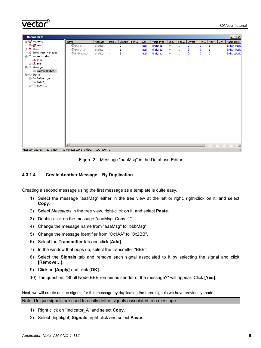
Our message "aaaMsg" should now look like this in the Overall View:
Application Note AN-AND-1-112
5
�
CANoe Tutorial
Figure 2 – Message "aaaMsg" in the Database Editor
Create Another Message – By Duplication
4.3.1.4
Creating a second message using the first message as a template is quite easy.
1) Select the message "aaaMsg" either in the tree view at the left or right, right-click on it, and select
Copy.
2) Select Messages in the tree view, right-click on it, and select Paste.
3) Double-click on the message "aaaMsg_Copy_1".
4) Change the message name from "aaaMsg" to "bbbMsg".
5) Change the message Identifier from "0x1AA" to "0x2BB".
6) Select the Transmitter tab and click [Add].
7)
8) Select the Signals tab and remove each signal associated to it by selecting the signal and click
In the window that pops up, select the transmitter "BBB".
[Remove…].
9) Click on [Apply] and click [OK].
10) The question: "Shall Node BBB remain as sender of the message?" will appear. Click [Yes].
Next, we will create unique signals for this message by duplicating the three signals we have previously made.
Note: Unique signals are used to easily define signals associated to a message.
1) Right click on “Indicator_A” and select Copy.
2) Select (highlight) Signals, right click and select Paste.
Application Note AN-AND-1-112
6
�
on it.
CANoe Tutorial
3) The signal Indicator_A_Copy_1 appears under the Signals list in the tree view at the left. Double click
4) Rename the signal to “Indicator_B” and click [Ok].
5) Repeat steps 1-4 to make “switch_1B” and “switch_2B”.
6) Assign theses signals to the message “bbbMessage”. Right click on “bbbMsg” and select Edit
Message….
7) Select the Signals tab and click [Add…]. Add the new signals.
8) Click Apply and OK.
9) Select “bbbMessage” in the tree view at the left.
10) Change the start bit of “switch_1B” to “0”, “switch_2B” to “1”, and “Indicator_B” to “8”.
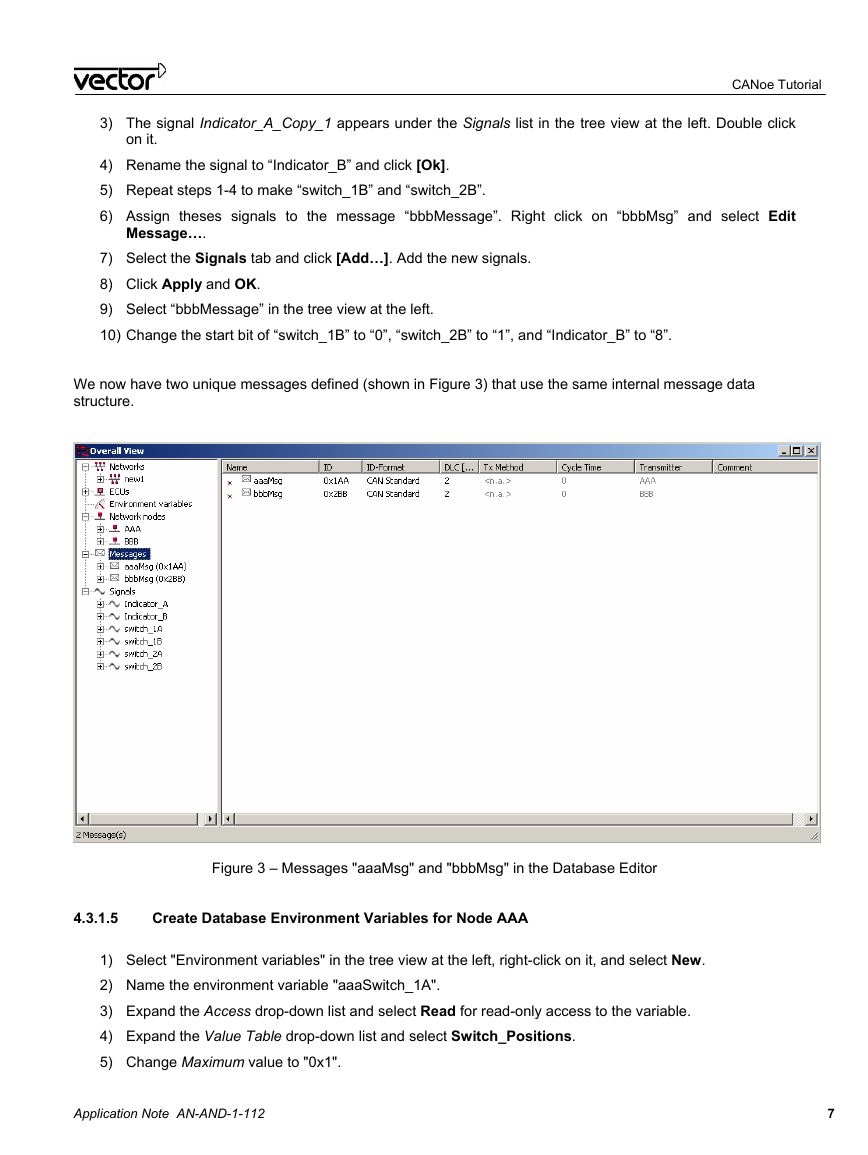
We now have two unique messages defined (shown in Figure 3) that use the same internal message data
structure.
Figure 3 – Messages "aaaMsg" and "bbbMsg" in the Database Editor
4.3.1.5
Create Database Environment Variables for Node AAA
1) Select "Environment variables" in the tree view at the left, right-click on it, and select New.
2) Name the environment variable "aaaSwitch_1A".
3) Expand the Access drop-down list and select Read for read-only access to the variable.
4) Expand the Value Table drop-down list and select Switch_Positions.
5) Change Maximum value to "0x1".
Application Note AN-AND-1-112
7
�
6) Go to the Control units tab and click [Add].
7) Select control unit "AAA" and click [OK].
8) Click [Apply] and then click [OK] to finish.
CANoe Tutorial
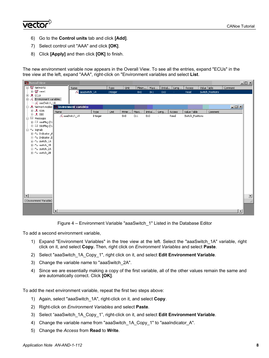
The new environment variable now appears in the Overall View. To see all the entries, expand "ECUs" in the
tree view at the left, expand "AAA", right-click on "Environment variables and select List.
Figure 4 – Environment Variable "aaaSwitch_1" Listed in the Database Editor
To add a second environment variable,
1) Expand "Environment Variables" in the tree view at the left. Select the "aaaSwitch_1A" variable, right
click on it, and select Copy. Then, right click on Environment Variables and select Paste.
2) Select "aaaSwitch_1A_Copy_1", right click on it, and select Edit Environment Variable.
3) Change the variable name to "aaaSwitch_2A".
4) Since we are essentially making a copy of the first variable, all of the other values remain the same and
are automatically correct. Click [OK].
To add the next environment variable, repeat the first two steps above:
1) Again, select "aaaSwitch_1A", right-click on it, and select Copy.
2) Right-click on Environment Variables and select Paste.
3) Select “aaaSwitch_1A_Copy_1”, right-click on it, and select Edit Environment Variable.
4) Change the variable name from "aaaSwitch_1A_Copy_1" to "aaaIndicator_A".
5) Change the Access from Read to Write.
Application Note AN-AND-1-112
8
�


 2023年江西萍乡中考道德与法治真题及答案.doc
 2012年重庆南川中考生物真题及答案.doc
 2013年江西师范大学地理学综合及文艺理论基础考研真题.doc
 2020年四川甘孜小升初语文真题及答案I卷.doc
 2020年注册岩土工程师专业基础考试真题及答案.doc
 2023-2024学年福建省厦门市九年级上学期数学月考试题及答案.doc
 2021-2022学年辽宁省沈阳市大东区九年级上学期语文期末试题及答案.doc
 2022-2023学年北京东城区初三第一学期物理期末试卷及答案.doc
 2018上半年江西教师资格初中地理学科知识与教学能力真题及答案.doc
 2012年河北国家公务员申论考试真题及答案-省级.doc
 2020-2021学年江苏省扬州市江都区邵樊片九年级上学期数学第一次质量检测试题及答案.doc
 2022下半年黑龙江教师资格证中学综合素质真题及答案.doc