Open Design Specification for .dwg files
Version 5.1
Open Design Alliance
www.opendesign.com
�
Copyright © 1998-2010 Open Design Alliance, Inc. All rights reserved.
Information in these materials is furnished for informational use only, is subject to change without notice and does not represent a
commitment on the part of Open Design Alliance. Open Design Alliance assumes no responsibility or liability for any errors or
inaccuracies that may appear in these materials. Use these materials at your own risk.
TO THE MAXIMUM EXTENT PERMITTED BY APPLICABLE LAW, OPEN DESIGN ALLIANCE AND ITS SUPPLIERS
DISCLAIM ANY AND ALL WARRANTIES AND CONDITIONS, EITHER EXPRESS OR IMPLIED, INCLUDING,
WITHOUT LIMITATION, IMPLIED WARRANTIES OF MERCHANTABILITY, FITNESS FOR A PARTICULAR
PURPOSE, TITLE, AND NON-INFRINGEMENT, AND THOSE ARISING OUT OF USAGE OF TRADE OR COURSE OF
DEALING, CONCERNING THESE MATERIALS. THESE MATERIALS ARE PROVIDED “AS IS” WITHOUT
WARRANTY OF ANY KIND.
TO THE MAXIMUM EXTENT PERMITTED BY APPLICABLE LAW, IN NO EVENT SHALL OPEN DESIGN ALLIANCE
OR ITS SUPPLIERS (OR THEIR RESPECTIVE AGENTS, DIRECTORS, EMPLOYEES OR REPRESENTATIVES) BE
LIABLE FOR ANY DAMAGES WHATSOEVER (INCLUDING, WITHOUT LIMITATION, CONSEQUENTIAL,
INCIDENTAL, DIRECT, INDIRECT, SPECIAL, ECONOMIC, PUNITIVE OR SIMILAR DAMAGES, OR DAMAGES FOR
LOSS OF BUSINESS PROFITS, LOSS OF GOODWILL, BUSINESS INTERRUPTION, COMPUTER FAILURE OR
MALFUNCTION, LOSS OF BUSINESS INFORMATION OR ANY AND ALL OTHER COMMERCIAL OR PECUNIARY
DAMAGES OR LOSSES) ARISING OUT OF THE USE OF THESE MATERIALS, HOWEVER CAUSED AND ON ANY
LEGAL THEORY OF LIABILITY (WHETHER IN TORT, CONTRACT OR OTHERWISE), EVEN IF OPEN DESIGN
ALLIANCE HAS BEEN ADVISED OF THE POSSIBILITY OF SUCH DAMAGES, OR FOR ANY CLAIM BY ANY OTHER
PARTY. Because some jurisdictions do not allow the exclusion or limitation of liability for consequential or incidental damages,
the above limitation may not apply to you.
Teigha™ is a trademark of Open Design Alliance in the United States and/or other countries. All other trademarks, trade names
or company names referenced herein are used for identification only and are the property of their respective owners.
US Government Restricted Rights: These materials are provided with RESTRICTED RIGHTS. Use, duplication or disclosure by
the Government is subject to restrictions as set forth in subparagraph (c)(1)(ii) of The Rights in Technical Data and Computer
Software clause at DFARS 252.227-7013 or subparagraphs (c)(1) and (2) of the Commercial Computer Software-Restricted
Rights at 48 CFR 52.227-19, as applicable. The contractor/manufacturer is Open Design Alliance, 5025 N Central Ave #602,
Phoenix, AZ, USA.
Printed in USA.
* DWG is the native and proprietary file format for AutoCAD® and a trademark of Autodesk, Inc. The Open Design Alliance is
not associated with Autodesk.
�
Open Design Specification for .dwg files
3
Open Design Specification for .dwg files
Table of Contents
1
Introduction .............................................................................................................................. 5
2 BIT CODES AND DATA DEFINITIONS .............................................................................. 6
3 R13-R15 DWG FILE FORMAT ORGANIZATION ............................................................ 19
4 R2004 DWG FILE FORMAT ORGANIZATION ................................................................ 21
5 R2007 DWG FILE FORMAT ORGANIZATION ................................................................ 33
6 R2010 DWG FILE FORMAT ORGANIZATION ................................................................ 64
7 Data section AcDb:Header (HEADER VARIABLES) ......................................................... 65
8 Data section AcDb:Classes .................................................................................................... 79
9
PADDING (R13C3 AND LATER) ....................................................................................... 81
10
Data section: “” .................................................................................................................. 82
Data section AcDb:SummaryInfo Section ......................................................................... 83
12
13
14
15
16
17
18
19
20
21
22
Data section AcDb:Preview ............................................................................................... 85
Data section AcDb:VBAProject Section ........................................................................... 87
Data section AcDb:AppInfo ............................................................................................... 88
Data section AcDb:FileDepList ......................................................................................... 90
Data section AcDb:RevHistory .......................................................................................... 92
Data section AcDb:Security ............................................................................................... 93
Data section AcDb:AcDbObjects ...................................................................................... 95
Data section AcDb:ObjFreeSpace .................................................................................... 209
Data section AcDb:Handles (OBJECT MAP) ................................................................. 210
UNKNOWN SECTION ................................................................................................... 211
SECOND FILE HEADER (R13-R15) ............................................................................. 212
�
Open Design Specification for .dwg files
4
Data section: AcDb:AuxHeader (Auxiliary file header) .................................................. 215
Extended Entity Data (Extended Object Data) ......................................................... 217
PROXY ENTITY GRAPHICS ........................................................................................ 218
23
24
25
�
Open Design Specification for .dwg files
5
1 Introduction
Originating in the late 1970s, drawing files created with microcomputer-based computer-aided design
software were saved with the .dwg extension. In the early 1980s, Autodesk® released AutoCAD® which
eventually became the most used CAD software in the world and which used Autodesk’s undocumented
and proprietary DWG™ file format (using the .dwg extension).
The Open Design Specification for .dwg files serves AutoCAD’s undocumented and proprietary DWG
file format. This specification includes DWG file format versions 13 up to and including version 2010.
Further, the Open Design Specification for .dwg files serves the Teigha™ software development platform
of the Open Design Alliance.
While our Open Design Specification for .dwg files is able to read and write .dwg files with excellent
AutoCAD compatibility, we continue to work to improve our understanding of all the data in a .dwg file.
If you find information which will help us to understand any unknown values, please contact us at
http://www.opendesign.com/contact.
�
Open Design Specification for .dwg files
6
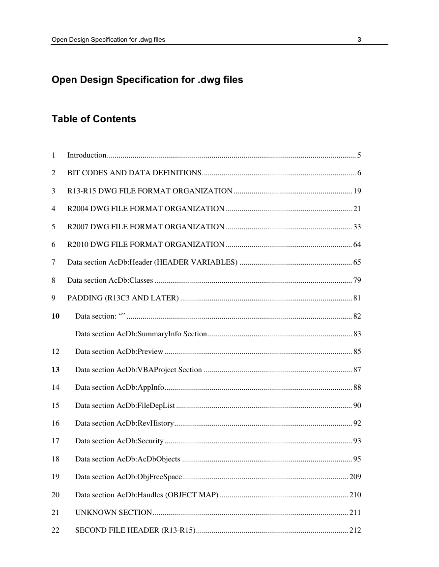
2 BIT CODES AND DATA DEFINITIONS
NOTE: Unless otherwise stated, all data in this manual is in little-endian order, with the least significant
byte first.
Much of the data in the DWG file format versions 13/14/2000/2004/2007/2010 must be read at the bit
level. Various parts of the drawing use data in compressed forms, which are explained below. Here are
the abbreviations used in this document for the various compressed forms:
B : bit (1 or 0)
BB : special 2 bit code (entmode in entities, for instance)
BS : bitshort
BL : bitlong
BD : bitdouble
2BD : 2D point (2 bitdoubles)
3BD : 3D point (3 bitdoubles)
RC : raw char (not compressed)
RS : raw short (not compressed)
RD : raw double (not compressed)
RL : raw long (not compressed)
2RD : 2 raw doubles
3RD : 3 raw doubles
MC : modular char
MS : modular short
H : handle reference (see the HANDLE REFERENCES section)
T : text (bitshort length, followed by the string).
TU : Unicode text (bitshort character length, followed by Unicode string, 2 bytes per
character). Unicode text is read from the “string stream” within the object data,
see the main Object description section for details.
TV : Variable text, T for 2004 and earlier files, TU for 2007+ files.
X : special form
U : unknown
SN : 16 byte sentinel
BE : BitExtrusion
DD : BitDouble With Default
BT : BitThickness
3DD : 3D point as 3 DD, needing 3 default values
CMC : CmColor value
OT : Object type
�
Open Design Specification for .dwg files
7
A “seeker” is an RL-type object which indicates either an absolute address in the file or an offset from
some known address.
A “sentinel” is 16 bytes of data used for file recovery purposes.
Generally, the compressed forms are used to allow for compression of common data, usually values like
0.0 and 1.0 for doubles, 0 and 256 for shorts. The method for interpreting the code is to read the first two
bits, which indicate either the size of the data to follow, or the actual value for the common values. Here
are the compressed formats and some examples of how they appear in the file:
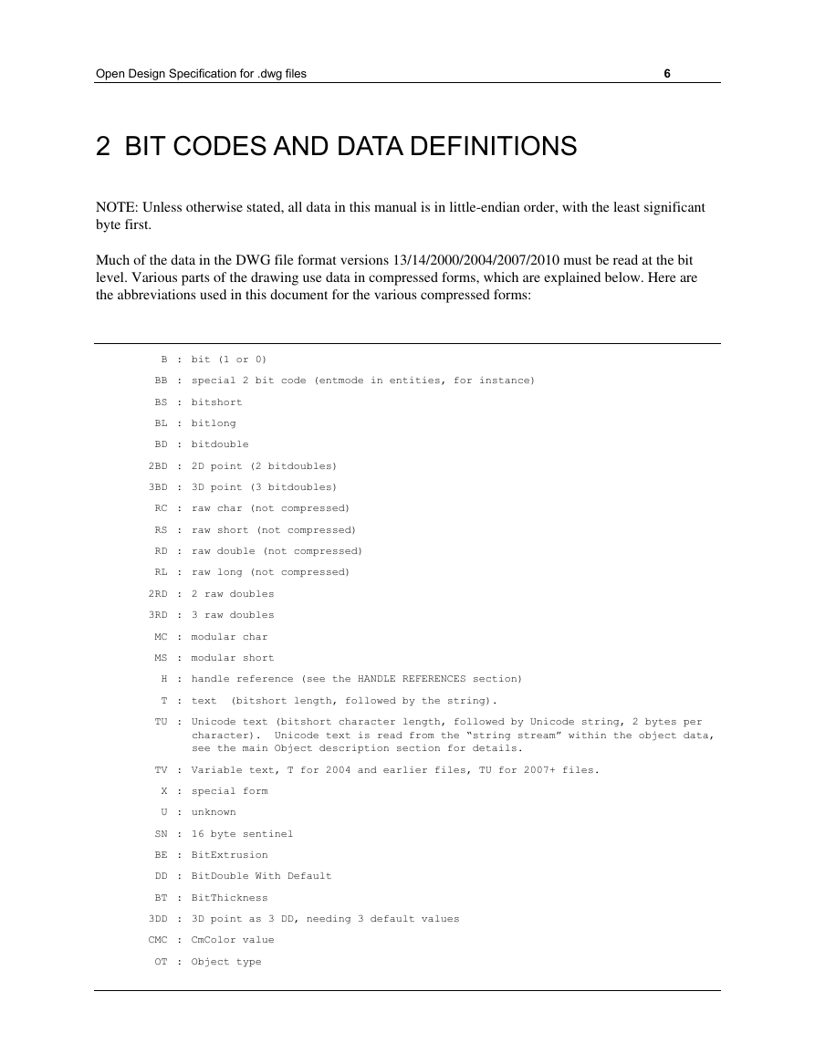
2.1 BITSHORT:
1st 2 bits : what it is
00 : A short (2 bytes) follows, little-endian order (LSB first)
01 : An unsigned char (1 byte) follows
10 : 0
11 : 256
The char size is used when positive shorts less than 256 are being stored. The short size is used when
values <0 or >=256 are being stored. Obviously the special cases for 0 and 256 are used when those
values are being stored.
Negative numbers use the short form, not the char form. That is, -1 is 00.11111111.11111111, not
01.11111111.
For instance, if we were known to be reading 5 shorts from the following stream of bits:
0000000001000000011011010000111110
It would be parsed like this:
00 00000001 00000001 (short 257)
10 (0)
11 (256)
01 00001111 (15)
10 (0)
2.2 BITLONG:
1st 2 bits : what it is
00 : A long (4 bytes) follows, little-endian order (LSB first)
01 : An unsigned char (1 byte) follows
10 : 0
11 : not used
The char size is used when positive longs less than 256 are being stored. The long size is used when
values <0 or >=256 are being stored. Obviously the special case for 0 is used when storing 0.
�
Open Design Specification for .dwg files
8
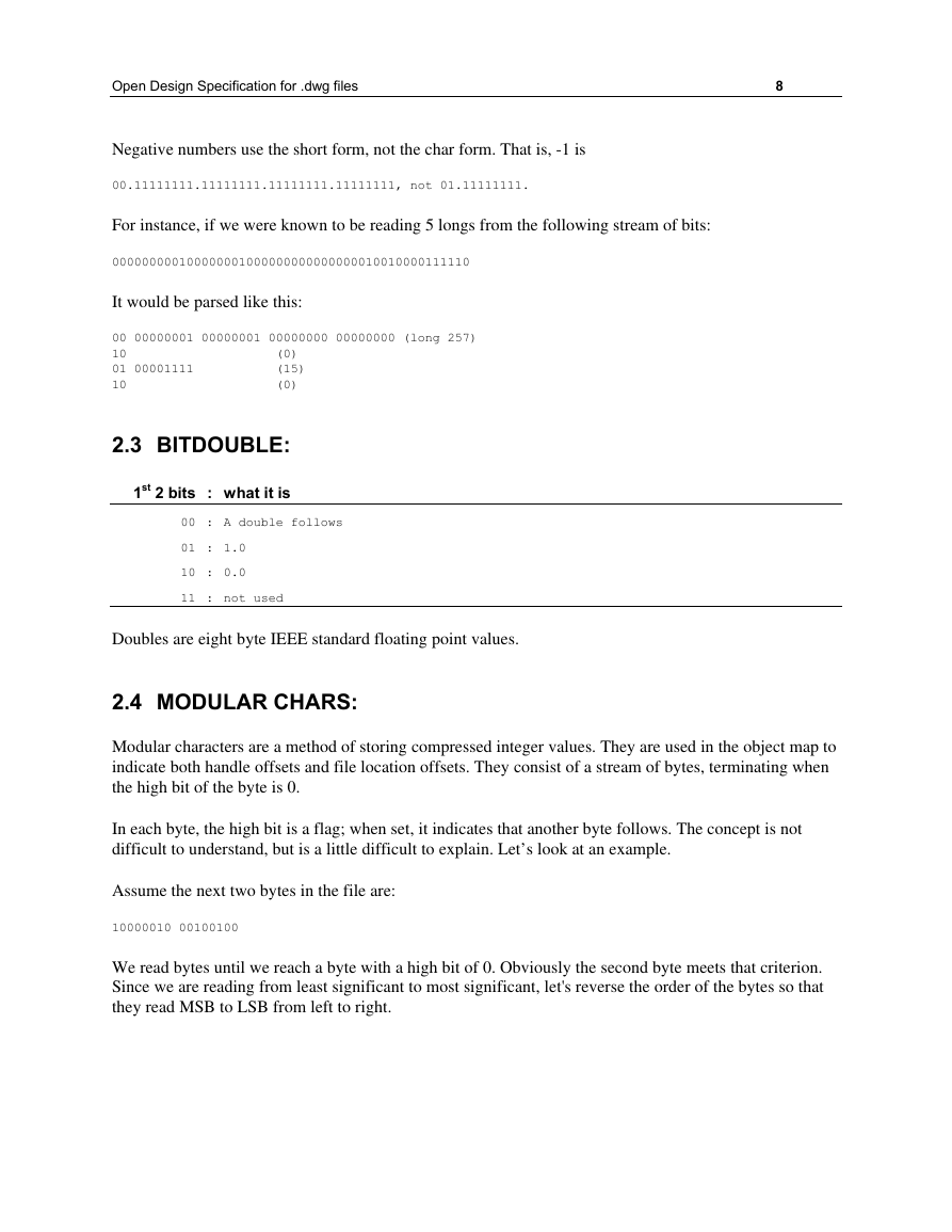
Negative numbers use the short form, not the char form. That is, -1 is
00.11111111.11111111.11111111.11111111, not 01.11111111.
For instance, if we were known to be reading 5 longs from the following stream of bits:
000000000100000001000000000000000010010000111110
It would be parsed like this:
00 00000001 00000001 00000000 00000000 (long 257)
10 (0)
01 00001111 (15)
10 (0)
2.3 BITDOUBLE:
1st 2 bits : what it is
00 : A double follows
01 : 1.0
10 : 0.0
11 : not used
Doubles are eight byte IEEE standard floating point values.
2.4 MODULAR CHARS:
Modular characters are a method of storing compressed integer values. They are used in the object map to
indicate both handle offsets and file location offsets. They consist of a stream of bytes, terminating when
the high bit of the byte is 0.
In each byte, the high bit is a flag; when set, it indicates that another byte follows. The concept is not
difficult to understand, but is a little difficult to explain. Let’s look at an example.
Assume the next two bytes in the file are:
10000010 00100100
We read bytes until we reach a byte with a high bit of 0. Obviously the second byte meets that criterion.
Since we are reading from least significant to most significant, let's reverse the order of the bytes so that
they read MSB to LSB from left to right.
�





 2023年江西萍乡中考道德与法治真题及答案.doc
 2012年重庆南川中考生物真题及答案.doc
 2013年江西师范大学地理学综合及文艺理论基础考研真题.doc
 2020年四川甘孜小升初语文真题及答案I卷.doc
 2020年注册岩土工程师专业基础考试真题及答案.doc
 2023-2024学年福建省厦门市九年级上学期数学月考试题及答案.doc
 2021-2022学年辽宁省沈阳市大东区九年级上学期语文期末试题及答案.doc
 2022-2023学年北京东城区初三第一学期物理期末试卷及答案.doc
 2018上半年江西教师资格初中地理学科知识与教学能力真题及答案.doc
 2012年河北国家公务员申论考试真题及答案-省级.doc
 2020-2021学年江苏省扬州市江都区邵樊片九年级上学期数学第一次质量检测试题及答案.doc
 2022下半年黑龙江教师资格证中学综合素质真题及答案.doc