DATA SHEET
NVIDIA Jetson TX1 System-on-Module
NVIDIA Tegra Processors: TD580D, TD570D, CD580M, CD570M
Description
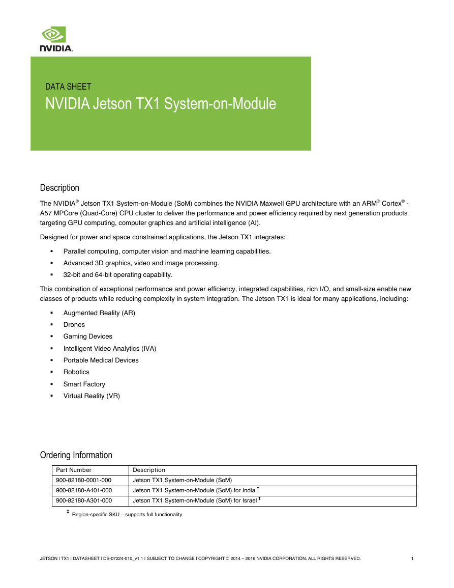
The NVIDIA® Jetson TX1 System-on-Module (SoM) combines the NVIDIA Maxwell GPU architecture with an ARM® Cortex® -
A57 MPCore (Quad-Core) CPU cluster to deliver the performance and power efficiency required by next generation products
targeting GPU computing, computer graphics and artificial intelligence (AI).
Designed for power and space constrained applications, the Jetson TX1 integrates:
Parallel computing, computer vision and machine learning capabilities.
Advanced 3D graphics, video and image processing.
32-bit and 64-bit operating capability.
This combination of exceptional performance and power efficiency, integrated capabilities, rich I/O, and small-size enable new
classes of products while reducing complexity in system integration. The Jetson TX1 is ideal for many applications, including:
Augmented Reality (AR)
Drones
Gaming Devices
Intelligent Video Analytics (IVA)
Portable Medical Devices
Robotics
Smart Factory
Virtual Reality (VR)
Ordering Information
Part Number
Description
900-82180-0001-000
900-82180-A401-000
900-82180-A301-000
Jetson TX1 System-on-Module (SoM)
Jetson TX1 System-on-Module (SoM) for India ‡
Jetson TX1 System-on-Module (SoM) for Israel ‡
‡
Region-specific SKU – supports full functionality
JETSON | TX1 | DATASHEET | DS-07224-010_v1.1 | SUBJECT TO CHANGE | COPYRIGHT © 2014 – 2016 NVIDIA CORPORATION. ALL RIGHTS RESERVED.
1
�
Jetson TX1 System-on-Module (SoM)
> Description
Maxwell GPU
Jetson TX1 Module
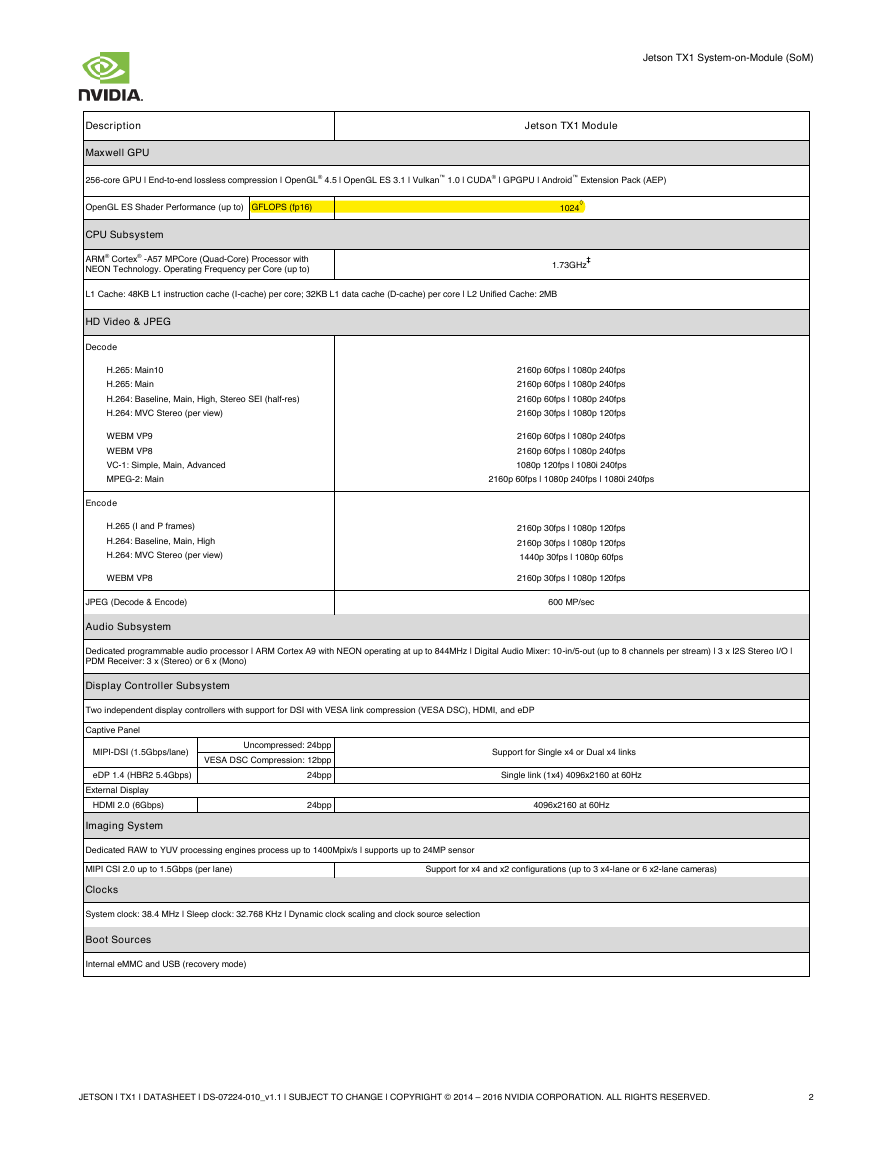
256-core GPU | End-to-end lossless compression | OpenGL® 4.5 | OpenGL ES 3.1 | Vulkan™ 1.0 | CUDA® | GPGPU | Android™ Extension Pack (AEP)
OpenGL ES Shader Performance (up to) GFLOPS (fp16)
CPU Subsystem
ARM® Cortex® -A57 MPCore (Quad-Core) Processor with
NEON Technology. Operating Frequency per Core (up to)
1024
◊
1.73GHz
‡
L1 Cache: 48KB L1 instruction cache (I-cache) per core; 32KB L1 data cache (D-cache) per core | L2 Unified Cache: 2MB
HD Video & JPEG
Decode
H.265: Main10
H.265: Main
H.264: Baseline, Main, High, Stereo SEI (half-res)
H.264: MVC Stereo (per view)
WEBM VP9
WEBM VP8
VC-1: Simple, Main, Advanced
MPEG-2: Main
Encode
H.265 (I and P frames)
H.264: Baseline, Main, High
H.264: MVC Stereo (per view)
WEBM VP8
JPEG (Decode & Encode)
Audio Subsystem
2160p 60fps | 1080p 240fps
2160p 60fps | 1080p 240fps
2160p 60fps | 1080p 240fps
2160p 30fps | 1080p 120fps
2160p 60fps | 1080p 240fps
2160p 60fps | 1080p 240fps
1080p 120fps | 1080i 240fps
2160p 60fps | 1080p 240fps | 1080i 240fps
2160p 30fps | 1080p 120fps
2160p 30fps | 1080p 120fps
1440p 30fps | 1080p 60fps
2160p 30fps | 1080p 120fps
600 MP/sec
Dedicated programmable audio processor | ARM Cortex A9 with NEON operating at up to 844MHz | Digital Audio Mixer: 10-in/5-out (up to 8 channels per stream) | 3 x I2S Stereo I/O |
PDM Receiver: 3 x (Stereo) or 6 x (Mono)
Display Controller Subsystem
Two independent display controllers with support for DSI with VESA link compression (VESA DSC), HDMI, and eDP
Captive Panel
MIPI-DSI (1.5Gbps/lane)
eDP 1.4 (HBR2 5.4Gbps)
External Display
HDMI 2.0 (6Gbps)
Imaging System
Uncompressed: 24bpp
VESA DSC Compression: 12bpp
24bpp
24bpp
Support for Single x4 or Dual x4 links
Single link (1x4) 4096x2160 at 60Hz
4096x2160 at 60Hz
Dedicated RAW to YUV processing engines process up to 1400Mpix/s | supports up to 24MP sensor
MIPI CSI 2.0 up to 1.5Gbps (per lane)
Support for x4 and x2 configurations (up to 3 x4-lane or 6 x2-lane cameras)
Clocks
System clock: 38.4 MHz | Sleep clock: 32.768 KHz | Dynamic clock scaling and clock source selection
Boot Sources
Internal eMMC and USB (recovery mode)
JETSON | TX1 | DATASHEET | DS-07224-010_v1.1 | SUBJECT TO CHANGE | COPYRIGHT © 2014 – 2016 NVIDIA CORPORATION. ALL RIGHTS RESERVED.
2
�
Jetson TX1 System-on-Module (SoM)
> Description
Security
Jetson TX1 Module
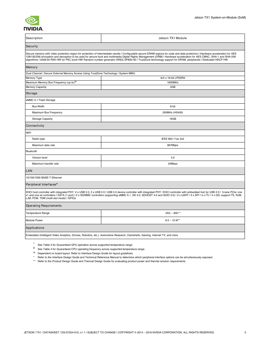
Secure memory with video protection region for protection of intermediate results | Configurable secure DRAM regions for code and data protection | Hardware acceleration for AES
128/192/256 encryption and decryption to be used for secure boot and multimedia Digital Rights Management (DRM) | Hardware acceleration for AES CMAC, SHA-1 and SHA-256
algorithms | 2048-bit RSA HW for PKC boot| HW Random number generator (RNG) SP800-90 | TrustZone technology support for DRAM, peripherals | Dedicated HDCP HW
Memory
Dual Channel | Secure External Memory Access Using TrustZone Technology | System MMU
Memory Type
Maximum Memory Bus Frequency (up to)††
Memory Capacity
Storage
eMMC 5.1 Flash Storage
Bus Width
Maximum Bus Frequency
Storage Capacity
Connectivity
WiFi
Radio type
Maximum data rate
Bluetooth
Version level
Maximum transfer rate
LAN
10/100/1000 BASE-T Ethernet
Peripheral Interfaces*
4ch x 16-bit LPDDR4
1600MHz
4GB
8-bit
200MHz (HS400)
16GB
IEEE 802.11ac 2x2
867Mbps
4.0
24Mbps
XHCI host controller with integrated PHY: 2 x USB 3.0, 3 x USB 2.0 | USB 3.0 device controller with integrated PHY | EHCI controller with embedded hub for USB 2.0 | 5-lane PCIe: one
x1 and one x4 controllers | SATA (1 port) | 2 x SD/MMC controllers (supporting eMMC 5.1, SD 4.0, SDHOST 4.0 and SDIO 3.0) | 3 x UART | 3 x SPI | 4 x I2C | 4 x I2S: support I2S, RJM,
LJM, PCM, TDM (multi-slot mode) | GPIOs
Operating Requirements
Temperature Range
Module Power
Applications
-25C – 80C**
6.5 – 15 W**
Embedded (Intelligent Video Analytics, Drones, Robotics, etc.), Automotive Research, Clamshells, Gaming, Internet TV, and more
◊
‡
See Table 3 for Guaranteed GPU operation across supported temperature range.
See Table 4 for Guaranteed CPU operating frequency across supported temperature range.
†† Dependent on board layout. Refer to Interface Design Guide for layout guidelines.
* Refer to the Interface Design Guide and Technical Reference Manual to determine which peripheral interface options can be simultaneously exposed.
** Refer to the Product Design Guide and Thermal Design Guide for evaluating product power and thermal solution requirements
JETSON | TX1 | DATASHEET | DS-07224-010_v1.1 | SUBJECT TO CHANGE | COPYRIGHT © 2014 – 2016 NVIDIA CORPORATION. ALL RIGHTS RESERVED.
3
�
Jetson TX1 System-on-Module (SoM)
Description
Initial Release
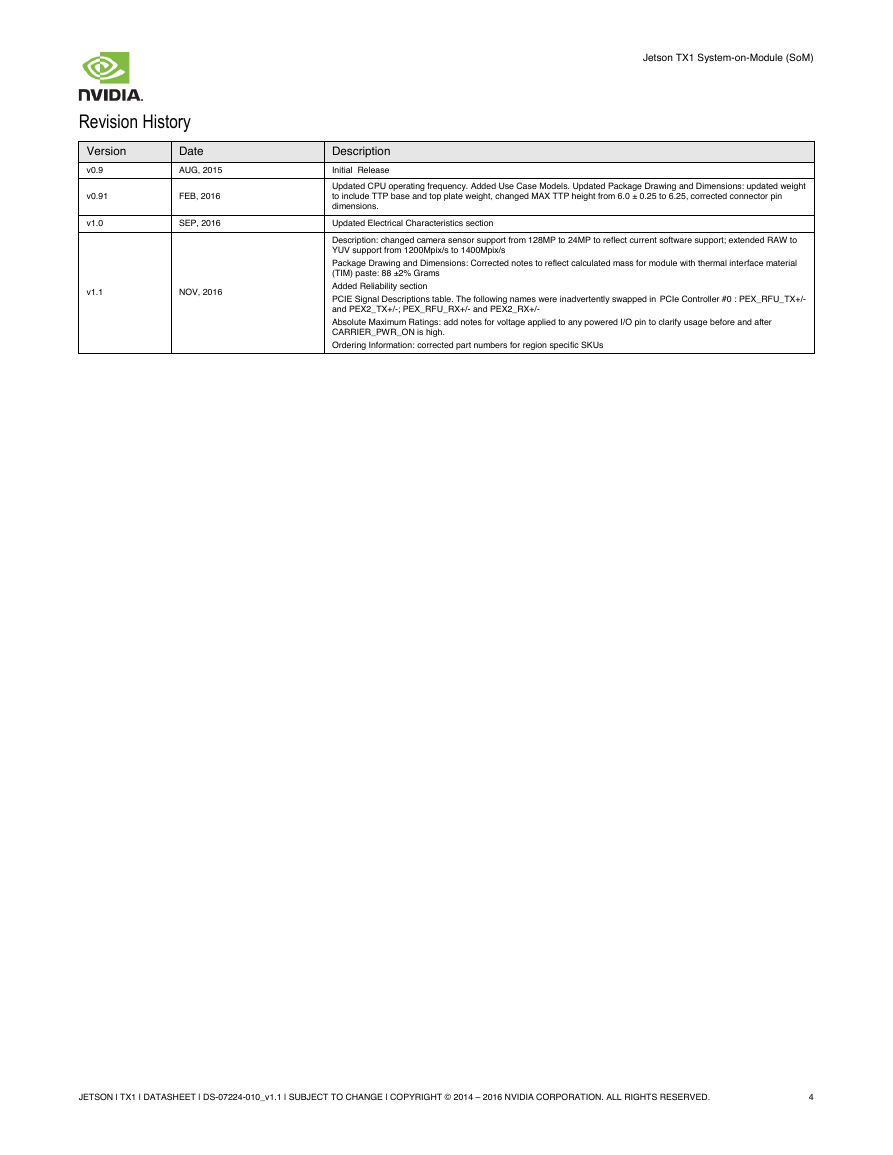
Updated CPU operating frequency. Added Use Case Models. Updated Package Drawing and Dimensions: updated weight
to include TTP base and top plate weight, changed MAX TTP height from 6.0 ± 0.25 to 6.25, corrected connector pin
dimensions.
Updated Electrical Characteristics section
Description: changed camera sensor support from 128MP to 24MP to reflect current software support; extended RAW to
YUV support from 1200Mpix/s to 1400Mpix/s
Package Drawing and Dimensions: Corrected notes to reflect calculated mass for module with thermal interface material
(TIM) paste: 88 ±2% Grams
Added Reliability section
PCIE Signal Descriptions table. The following names were inadvertently swapped in PCIe Controller #0 : PEX_RFU_TX+/-
and PEX2_TX+/-; PEX_RFU_RX+/- and PEX2_RX+/-
Absolute Maximum Ratings: add notes for voltage applied to any powered I/O pin to clarify usage before and after
CARRIER_PWR_ON is high.
Ordering Information: corrected part numbers for region specific SKUs
Revision History
Version
Date
v0.9
v0.91
v1.0
AUG, 2015
FEB, 2016
SEP, 2016
v1.1
NOV, 2016
JETSON | TX1 | DATASHEET | DS-07224-010_v1.1 | SUBJECT TO CHANGE | COPYRIGHT © 2014 – 2016 NVIDIA CORPORATION. ALL RIGHTS RESERVED.
4
�
Table of Contents
1.0 Module Overview
Jetson TX1 System-on-Module (SoM)
7
1.1
1.2
1.3
1.4
1.5
1.6
1.7
1.8
1.9
Tegra X1 SoC .............................................................................................................................................. 8
Memory ........................................................................................................................................................ 8
Storage ........................................................................................................................................................ 8
Connectivity ................................................................................................................................................. 8
Networking ................................................................................................................................................... 9
Power ........................................................................................................................................................... 9
Thermal Transfer Plate ................................................................................................................................ 9
Board-to-board Connector ........................................................................................................................... 9
WiFi/BT Antenna Connector ........................................................................................................................ 9
2.0 Power and System Management
10
Use Case Models ...................................................................................................................................... 10
Power Rails................................................................................................................................................ 11
2.2.1 VDD_IN ........................................................................................................................................ 11
2.2.2 VDD_RTC .................................................................................................................................... 11
2.2.3 IO Rail Voltages ........................................................................................................................... 11
Power Sequencing .................................................................................................................................... 11
2.3.1 Power Up ..................................................................................................................................... 11
2.3.2 Power Down ................................................................................................................................. 12
Power States ............................................................................................................................................. 12
2.4.1 ON State ...................................................................................................................................... 13
2.4.2 OFF State ..................................................................................................................................... 13
2.4.3 SLEEP State ................................................................................................................................ 13
Thermal Management ............................................................................................................................... 14
Clocks ........................................................................................................................................................ 14
WiFi Power States ..................................................................................................................................... 15
2.7.1 STA Mode .................................................................................................................................... 15
2.7.2 P2P Group-owner Powersave States .......................................................................................... 15
Bluetooth Power States ............................................................................................................................. 15
Ethernet ..................................................................................................................................................... 15
2.1
2.2
2.3
2.4
2.5
2.6
2.7
2.8
2.9
3.1
3.2
3.3
3.0 Interface and Signal Descriptions
16
SD/eMMC Controller ................................................................................................................................. 16
Serial ATA (SATA) Controller .................................................................................................................... 17
Display Interfaces ...................................................................................................................................... 17
3.3.1 MIPI Display Serial Interface (DSI) .............................................................................................. 17
3.3.2 High-Definition Multimedia Interface (HDMI) and DisplayPort (DP) Interfaces ........................... 18
3.3.3 Embedded DisplayPort (eDP) Interface ....................................................................................... 20
Audio Interfaces ......................................................................................................................................... 20
USB Interfaces........................................................................................................................................... 21
PCI Express (PCIe) Interface .................................................................................................................... 22
Serial Peripheral Interface ......................................................................................................................... 23
Inter-Chip Communication (I2C) Controller ............................................................................................... 25
UART Controller ........................................................................................................................................ 25
Video Input Interfaces .............................................................................................................................. 26
3.10.1 MIPI Camera Serial Interface (CSI) ........................................................................................... 26
3.10.2 Camera / VI (Video Input) .......................................................................................................... 27
Miscellaneous Interfaces ......................................................................................................................... 28
3.11.1 Debug ......................................................................................................................................... 28
3.11.2 Pulse Width/Frequency Modulation (PWFM) ............................................................................. 28
3.4
3.5
3.6
3.7
3.8
3.9
3.10
3.11
JETSON | TX1 | DATASHEET | DS-07224-010_v1.1 | SUBJECT TO CHANGE | COPYRIGHT © 2014 – 2016 NVIDIA CORPORATION. ALL RIGHTS RESERVED.
5
�
4.0 Pin Definitions
Jetson TX1 System-on-Module (SoM)
29
4.1
4.2
4.3
4.4
4.5
Power-on Reset Behavior .......................................................................................................................... 30
Deep Sleep Behavior ................................................................................................................................. 30
GPIO Controller ......................................................................................................................................... 31
Pin Assignments ........................................................................................................................................ 32
Pin Descriptions ......................................................................................................................................... 33
5.0 Physical / Electrical Characteristics
40
5.1
5.2
5.3
5.4
5.5
Absolute Maximum Ratings ....................................................................................................................... 40
Digital Logic ............................................................................................................................................... 41
Thermal ...................................................................................................................................................... 41
Reliability ................................................................................................................................................... 41
Package Drawing and Dimensions ........................................................................................................... 42
JETSON | TX1 | DATASHEET | DS-07224-010_v1.1 | SUBJECT TO CHANGE | COPYRIGHT © 2014 – 2016 NVIDIA CORPORATION. ALL RIGHTS RESERVED.
6
�
Jetson TX1 System-on-Module (SoM)
1.0 Module Overview
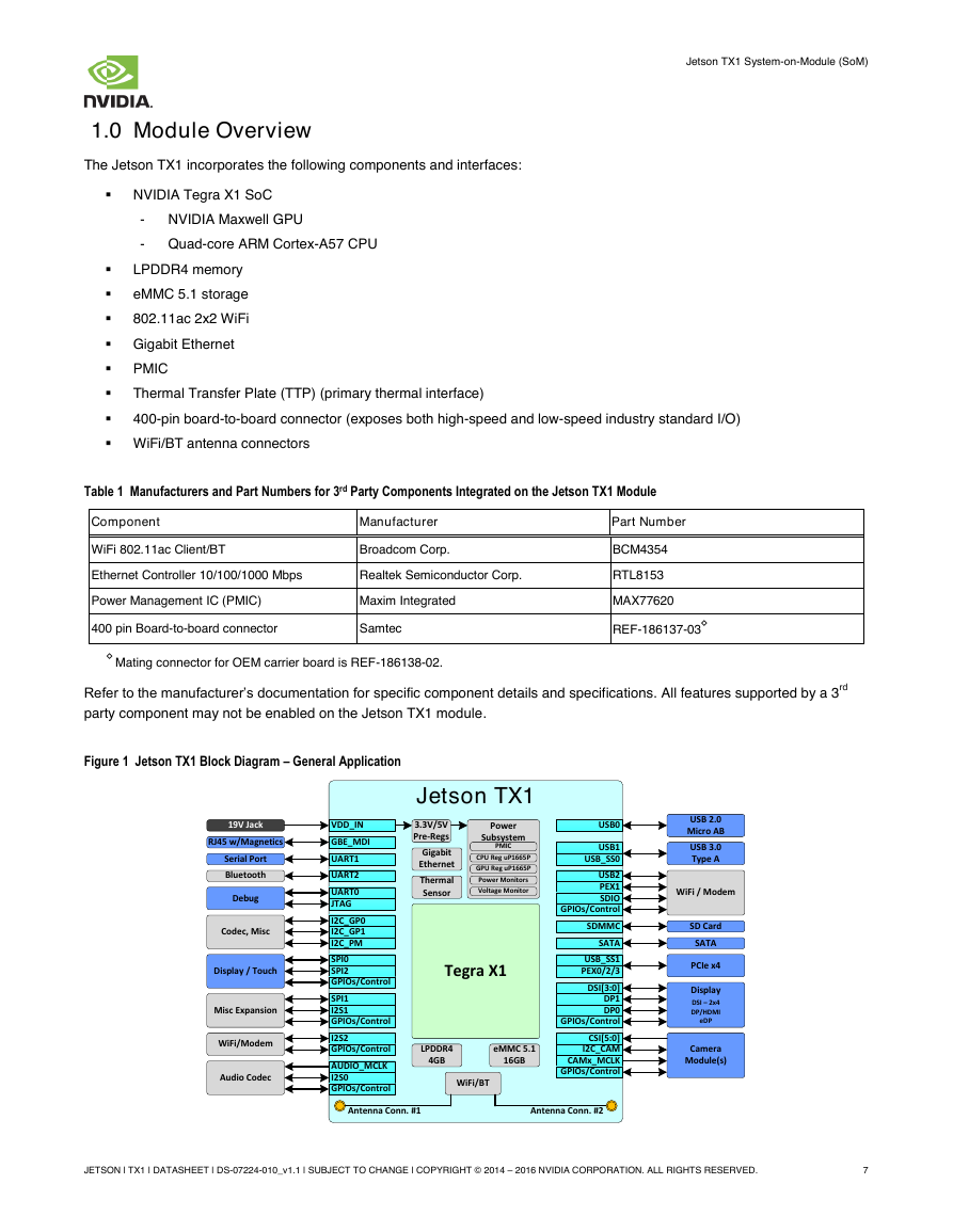
The Jetson TX1 incorporates the following components and interfaces:
NVIDIA Tegra X1 SoC
- NVIDIA Maxwell GPU
- Quad-core ARM Cortex-A57 CPU
LPDDR4 memory
eMMC 5.1 storage
802.11ac 2x2 WiFi
Gigabit Ethernet
PMIC
Thermal Transfer Plate (TTP) (primary thermal interface)
400-pin board-to-board connector (exposes both high-speed and low-speed industry standard I/O)
WiFi/BT antenna connectors
Table 1 Manufacturers and Part Numbers for 3rd Party Components Integrated on the Jetson TX1 Module
Component
Manufacturer
Part Number
WiFi 802.11ac Client/BT
Broadcom Corp.
Ethernet Controller 10/100/1000 Mbps
Realtek Semiconductor Corp.
Power Management IC (PMIC)
Maxim Integrated
400 pin Board-to-board connector
Samtec
◊
Mating connector for OEM carrier board is REF-186138-02.
BCM4354
RTL8153
MAX77620
REF-186137-03
◊
Refer to the manufacturer’s documentation for specific component details and specifications. All features supported by a 3rd
party component may not be enabled on the Jetson TX1 module.
Figure 1 Jetson TX1 Block Diagram – General Application
JETSON | TX1 | DATASHEET | DS-07224-010_v1.1 | SUBJECT TO CHANGE | COPYRIGHT © 2014 – 2016 NVIDIA CORPORATION. ALL RIGHTS RESERVED.
7
Jetson TX1Gigabit EthernetLPDDR44GBeMMC 5.116GBRJ45 w/MagneticsUSB 2.0Micro ABUSB 3.0Type ASATA3.3V/5VPre-Regs19V JackWiFi/BTSD CardAudio CodecPCIe x4CameraModule(s)VDD_INDebugSerial PortUSB0USB1PEX1USB2GBE_MDII2S2SATASDIOUART2AUDIO_MCLKI2S0PEX0/2/3I2C_CAMI2C_GP0CSI[5:0]DP1SDMMCUSB_SS0DP0SPI1I2S1UART0JTAGI2C_GP1UART1DSI[3:0]SPI0SPI2USB_SS1CAMx_MCLKDisplayWiFi/ModemMisc ExpansionDisplay / TouchCodec, MiscWiFi / ModemBluetoothPowerSubsystemPMICCPU Reg uP1665PGPU Reg uP1665PDSI – 2x4DP/HDMIeDPGPIOs/ControlGPIOs/ControlGPIOs/ControlGPIOs/ControlGPIOs/ControlGPIOs/ControlGPIOs/ControlI2C_PMAntenna Conn. #1Antenna Conn. #2Tegra X1ThermalSensorPower MonitorsVoltage Monitor�
Jetson TX1 System-on-Module (SoM)
1.1
Tegra X1 SoC
The NVIDIA Tegra® X1 SoC couples the latest NVIDIA Maxwell™ GPU architecture with an ARM®v8 CPU cluster to deliver
high performance and power efficiency. The Maxwell GPU implements a number of architectural enhancements designed to
extract maximum performance per watt consumed. Designed for use in power-limited environments, Tegra X1 processors
enable industry-leading visual computing capabilities, 32-bit and 64-bit operating capability, and integrate advanced multi-
function audio, video and image processing pipelines that exceed performance targets for next generation small form factor
(SFF) devices.
1.2
Memory
On-board 4GB of LPDDR4, over a 4 channel x 16-bit interface. The maximum frequency is 1600MHz. The theoretical peak
memory bandwidth is 25.6 GB/s.
1.3
Storage
On-board 16GB of eMMC 5.1 flash storage. The theoretical peak bandwidth is 400 MB/s
1.4
Connectivity
WiFi/Bluetooth integrated on the Jetson TX1 module supports:
WiFi Ready
-
-
-
802.11ac compliant (backwards compatible with legacy 802.11b/g/a/n devices)
867Mbps PHY maximum data rate
2x2 MIMO
Bluetooth Ready
-
Bluetooth 4.0 ready (can connect to Bluetooth 4.0 enabled devices)
- HIDP
- RFKILL
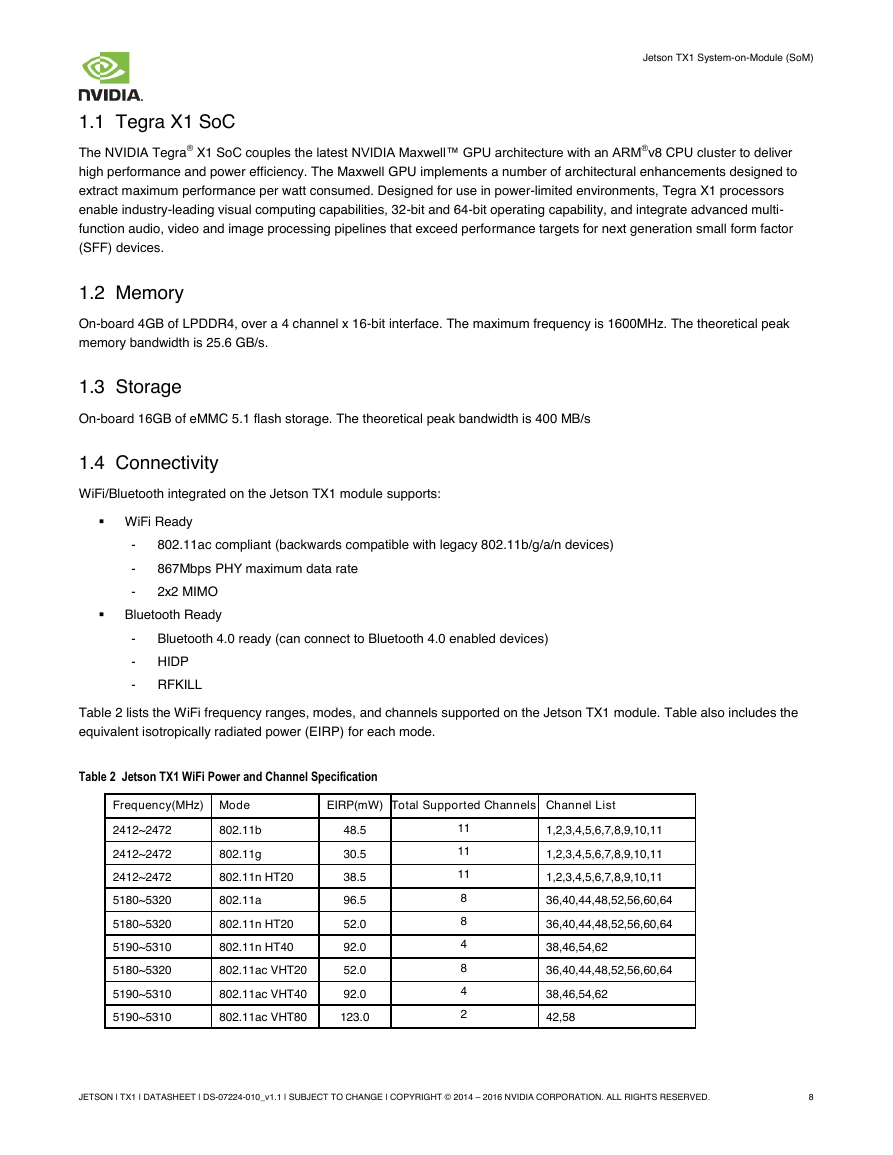
Table 2 lists the WiFi frequency ranges, modes, and channels supported on the Jetson TX1 module. Table also includes the
equivalent isotropically radiated power (EIRP) for each mode.
Table 2 Jetson TX1 WiFi Power and Channel Specification
Frequency(MHz) Mode
EIRP(mW) Total Supported Channels Channel List
2412~2472
2412~2472
2412~2472
5180~5320
5180~5320
5190~5310
5180~5320
5190~5310
5190~5310
802.11b
802.11g
802.11n HT20
802.11a
802.11n HT20
802.11n HT40
802.11ac VHT20
802.11ac VHT40
802.11ac VHT80
48.5
30.5
38.5
96.5
52.0
92.0
52.0
92.0
123.0
11
11
11
8
8
4
8
4
2
1,2,3,4,5,6,7,8,9,10,11
1,2,3,4,5,6,7,8,9,10,11
1,2,3,4,5,6,7,8,9,10,11
36,40,44,48,52,56,60,64
36,40,44,48,52,56,60,64
38,46,54,62
36,40,44,48,52,56,60,64
38,46,54,62
42,58
JETSON | TX1 | DATASHEET | DS-07224-010_v1.1 | SUBJECT TO CHANGE | COPYRIGHT © 2014 – 2016 NVIDIA CORPORATION. ALL RIGHTS RESERVED.
8
�




 2023年江西萍乡中考道德与法治真题及答案.doc
 2012年重庆南川中考生物真题及答案.doc
 2013年江西师范大学地理学综合及文艺理论基础考研真题.doc
 2020年四川甘孜小升初语文真题及答案I卷.doc
 2020年注册岩土工程师专业基础考试真题及答案.doc
 2023-2024学年福建省厦门市九年级上学期数学月考试题及答案.doc
 2021-2022学年辽宁省沈阳市大东区九年级上学期语文期末试题及答案.doc
 2022-2023学年北京东城区初三第一学期物理期末试卷及答案.doc
 2018上半年江西教师资格初中地理学科知识与教学能力真题及答案.doc
 2012年河北国家公务员申论考试真题及答案-省级.doc
 2020-2021学年江苏省扬州市江都区邵樊片九年级上学期数学第一次质量检测试题及答案.doc
 2022下半年黑龙江教师资格证中学综合素质真题及答案.doc