PART 1 Electrical and Electronic Engineering Basics
UNIT 1 A Electrical Networks — — — — — — — —
— — — — 3
B Three-phase Circuits
UNIT 2 A The Operational Amplifier — — — — — — —
— — — — 5
B Transistors
UNIT 3 A Logical Variables and Flip-flop — — — — —
— — — — — 8
B Binary Number System
UNIT 4 A Power Semiconductor Devices — — — — — —
— — — — 11
B Power Electronic Converters
UNIT 5 A Types of DC Motors — — — — — — — — — —
— — —15
B Closed-loop Control of DC Drivers
UNIT 6 A AC Machines — — — — — — — — — — — —
— — —19
B Induction Motor Drive
UNIT 7 A Electric Power System — — — — — — — —
— — — —22
1
�
B Power System Automation
PART 2 Control Theory
UNIT 1 A The World of Control — — — — — — — — —
— — —27
B The Transfer Function and the Laplace Transformation
— — — — —29
UNIT 2 A Stability and the Time Response — — — — —
— — — — 30
B Steady State— — — — — — — — — — — — —
— —— — 31
UNIT 3 A The Root Locus — — — — — — — — — —
—— — 32
B The Frequency Response Methods: Nyquist Diagrams —
— — — — 33
UNIT 4 A The Frequency Response Methods: Bode Piots — —
— — — 34
B Nonlinear Control System 37
UNIT 5 A Introduction to Modern Control Theory
38
B State Equations
40
UNIT 6 A Controllability, Observability, and Stability
B Optimum Control Systems
2
�
UNIT 7 A Conventional and Intelligent Control
B Artificial Neural Network
PART 3
Computer Control Technology
UNIT 1 A Computer Structure and Function
42
B Fundamentals of Computer and Networks 43
UNIT 2 A Interfaces to External Signals and Devices 44
B The Applications of Computers
46
UNIT 3 A PLC Overview
B PACs for Industrial Control, the Future of
Control
UNIT 4 A Fundamentals of Single-chip Microcomputer
49
B Understanding DSP and Its Uses
UNIT 5 A A First Look at Embedded Systems
B Embedded Systems Design
PART 4
Process Control
UNIT 1 A A Process Control System 50
B Fundamentals of Process Control
52
UNIT 2 A Sensors and Transmitters 53
B Final Control Elements and Controllers
UNIT 3 A P Controllers and PI Controllers
B PID Controllers and Other Controllers
UNIT 4 A Indicating Instruments
3
�
B Control Panels
PART 5
Control Based on Network and Information
UNIT 1 A Automation Networking Application Areas
B Evolution of Control System Architecture
UNIT 2 A Fundamental Issues in Networked Control Systems
B Stability of NCSs with Network-induced Delay
UNIT 3 A Fundamentals of the Database System
B Virtual Manufacturing—A Growing Trend in
Automation
UNIT 4 A Concepts of Computer Integrated Manufacturing
B Enterprise Resources Planning and Beyond
PART 6
Synthetic Applications of Automatic
Technology
UNIT 1 A Recent Advances and Future Trends in Electrical
Machine Drivers
B System Evolution in Intelligent Buildings
UNIT 2 A Industrial Robot
B A General Introduction to Pattern Recognition
UNIT 3 A Renewable Energy
4
�
B Electric Vehicles
UNIT 1
A 电路
电路或电网络由以某种方式连接的电阻器、电感器和电容器等元
件组成。如果网络不包含能源,如电池或发电机,那么就被称作无源
网络。换句话说,如果存在一个或多个能源,那么组合的结果为有源
网络。在研究电网络的特性时,我们感兴趣的是确定电路中的电压和
电流。因为网络由无源电路元件组成,所以必须首先定义这些元件的
电特性.
就电阻来说,电压-电流的关系由欧姆定律给出,欧姆定律指出:
电阻两端的电压等于电阻上流过的电流乘以电阻值。在数学上表达
5
�
为: u=iR (1-1A-1)式中 u=电压,伏特;i =电流,安培;R = 电阻,
欧姆。
纯电感电压由法拉第定律定义,法拉第定律指出:电感两端的电
压正比于流过电感的电流随时间的变化率。因此可得到:U=Ldi/dt 式
中 di/dt = 电流变化率, 安培/秒; L = 感应系数, 享利。
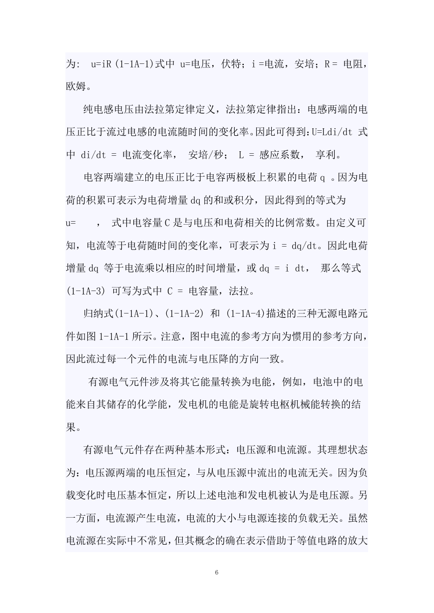
电容两端建立的电压正比于电容两极板上积累的电荷 q 。因为电
荷的积累可表示为电荷增量 dq 的和或积分,因此得到的等式为
u= , 式中电容量 C 是与电压和电荷相关的比例常数。由定义可
知,电流等于电荷随时间的变化率,可表示为 i = dq/dt。因此电荷
增量 dq 等于电流乘以相应的时间增量,或 dq = i dt, 那么等式
(1-1A-3) 可写为式中 C = 电容量,法拉。
归纳式(1-1A-1)、(1-1A-2) 和 (1-1A-4)描述的三种无源电路元
件如图 1-1A-1 所示。注意,图中电流的参考方向为惯用的参考方向,
因此流过每一个元件的电流与电压降的方向一致。
有源电气元件涉及将其它能量转换为电能,例如,电池中的电
能来自其储存的化学能,发电机的电能是旋转电枢机械能转换的结
果。
有源电气元件存在两种基本形式:电压源和电流源。其理想状态
为:电压源两端的电压恒定,与从电压源中流出的电流无关。因为负
载变化时电压基本恒定,所以上述电池和发电机被认为是电压源。另
一方面,电流源产生电流,电流的大小与电源连接的负载无关。虽然
电流源在实际中不常见,但其概念的确在表示借助于等值电路的放大
6
�
器件,比如晶体管中具有广泛应用。电压源和电流源的符号表示如图
1-1A-2 所示。
分析电网络的一般方法是网孔分析法或回路分析法。应用于此方
法的基本定律是基尔霍夫第一定律,基尔霍夫第一定律指出:一个闭
合回路中的电压代数和为 0,换句话说,任一闭合回路中的电压升等
于电压降。网孔分析指的是:假设有一个电流——即所谓的回路电流
——流过电路中的每一个回 路,求每一个回路电压降的代数和,并
令其为零。
考虑图 1-1A-3a 所示的电路,其由串联到电压源上的电感和电阻
组成,假设回路电流 i ,那么回路总的电压降为 因为在假定的电流
方向上,输入电压代表电压升的方向,所以输电压在(1-1A-5)式中
为负。因为电流方向是电压下降的方向,所以每一个无源元件的压降
为正。利用电阻和电感压降公式,可得等式(1-1A-6)是电路电流的微
分方程式。
或许在电路中,人们感兴趣的变量是电感电压而不是电感电流。
正如图 1-1A-1 指出的用积分代替式(1-1A-6)中的 i,可得 1-1A-7
B 三相电路
三相电路不过是三个单相电路的组合。因为这个事实,所以平衡
三相电路的电流、电压和功率关系可通过在三相电路的组合元件中应
用单相电路的规则来研究。这样看来,三相电路比单相电路的分析难
7
�
不了多少。使用三相电路的原因在单相电路中,功率本身是脉动的。
在功率因数为 1 时,单相电路的功率值每个周波有两次为零。当功率
因数小于 1 时,功率在每个周波的部分时间里为负。 虽然供给三
相电路中每一相的功率是脉动的,但可证明供给平衡三相电路的总功
率是恒定的。基于此,总的来说三相电气设备的特性优于类似的单相
电气设备的特性。三相供电的机械和控制设备与相同额定容量的单相
供电的设备相比: 体积小, 重量轻,效率高。除了三相系统提供的
上述优点,三相电的传输需要的铜线仅仅是同样功率大小单相电传输
所需铜线的 3/4。三相电压的产生三相电路可由三个频率相同在时间
相位上相差 120°电角度的电动势供电。这样的三相正弦电动势如图
1-1B-1 所示。这些电动势由交流发电机的三套独立电枢线圈产生,
这三套线圈安装在发电机电枢上,互相之间相差 120°电角度。线圈
的头尾可以从发电机中全部引出,组成三个独立的单相电路。然而一
般线圈无论在内部或在外部均会相互连接,形成三线或四线三相系
统。连接三相发电机线圈有两种方法,一般来说,把任何类型的装置
连接到三相电路也存在两种方法。它们是星(Y)形联接和角(D)形
联接。大多数发电机是星(Y)形联接,但负载可以是星(Y)形联接
或角(D)形联接。 星(Y)形联接发电机的电压关系 图 1-1B-2a
表示发电机的三个线圈或相绕组。这些绕组在电枢表面上是按它们产
生的电动势在时间相位上相差 120°分布的。每一个线圈的两端均标
有字母 S 和 F (起始和终结)。图 1-1B-2a 中,所有标有 S 的线圈端
连接到一个公共点 N,三个标有 F 的线圈端被引出到接线端 A、B 和 C ,
8
�



 2023年江西萍乡中考道德与法治真题及答案.doc
 2012年重庆南川中考生物真题及答案.doc
 2013年江西师范大学地理学综合及文艺理论基础考研真题.doc
 2020年四川甘孜小升初语文真题及答案I卷.doc
 2020年注册岩土工程师专业基础考试真题及答案.doc
 2023-2024学年福建省厦门市九年级上学期数学月考试题及答案.doc
 2021-2022学年辽宁省沈阳市大东区九年级上学期语文期末试题及答案.doc
 2022-2023学年北京东城区初三第一学期物理期末试卷及答案.doc
 2018上半年江西教师资格初中地理学科知识与教学能力真题及答案.doc
 2012年河北国家公务员申论考试真题及答案-省级.doc
 2020-2021学年江苏省扬州市江都区邵樊片九年级上学期数学第一次质量检测试题及答案.doc
 2022下半年黑龙江教师资格证中学综合素质真题及答案.doc