logo资料库

UFS-Universal Flash Storage Host Controller Interface (UFSHCI).pdf

第1页 / 共84页
第2页 / 共84页
第3页 / 共84页
第4页 / 共84页
第5页 / 共84页
第6页 / 共84页
第7页 / 共84页
第8页 / 共84页
资料共84页,剩余部分请下载后查看
1 Scope
2 Normative Reference
3 Acronyms, Terms and Definitions, Keywords, and Conventions
4 Architectural Overview
4.1 Outside of Scope
4.2 Interface Architecture
4.2 Interface Architecture (cont’d)
4.3 Transfer Request Interface
4.3 Transfer Request Interface (cont’d)
4.4 Limitations
5 UFS Host Controller Register Interface
5.1 Register Map
5.2 Host Controller Capabilities Registers
5.2.1 Offset 00h: CAP – Controller Capabilities
5.2 Host Controller Capabilities Registers (cont’d)
5.2.2 Offset 08h: VER – UFS Version
5.2.3 Offset 10h: HCPID – Host Controller Identification Descriptor – Product ID
5.2.4 Offset 14h: HCMID – Host Controller Identification Descriptor – Manufacturer ID
5.2.5 Offset 18h: AHIT – Auto-Hibernate Idle Timer
5.3 Operation and Runtime Registers
5.3.1 Offset 20h: IS – Interrupt Status
5.3 Operation and Runtime Registers (cont’d)
5.3.2 Offset 24h: IE – Interrupt Enable
5.3 Operation and Runtime Registers (cont’d)
5.3.3 Offset 30h: HCS – Host Controller Status
5.3 Operation and Runtime Registers (cont’d)
5.3.4 Offset 34h: HCE – Host Controller Enable
5.3.5 Offset 38h: UECPA – Host UIC Error Code PHY Adapter Layer
5.3 Operation and Runtime Registers (cont’d)
5.3.6 Offset 3Ch: UECDL – Host UIC Error Code Data Link Layer
5.3.7 Offset 40h: UECN – Host UIC Error Code Network Layer
5.3 Operation and Runtime Registers (cont’d)
5.3.8 Offset 44h: UECT – Host UIC Error Code Transport Layer
5.3.9 Offset 48h: UECDME – Host UIC Error Code
5.3 Operation and Runtime Registers (cont’d)
5.3.10 Offset 4Ch: UTRIACR – UTP Transfer Request Interrupt Aggregation Control Register
5.3 Operation and Runtime Registers (cont’d)
5.3.10 Offset 4Ch: UTRIACR – UTP Transfer Request Interrupt Aggregation Control Register (cont’d)
5.4 UTP Transfer Request Registers
5.4.1 Offset 50h: UTRLBA – UTP Transfer Request List Base Address
5.4.2 Offset 54h: UTRLBAU – UTP Transfer Request List Base Address Upper 32-bits
5.4.3 Offset 58h: UTRLDBR – UTP Transfer Request List Door Bell Register
5.4.4 Offset 5Ch: UTRLCLR – UTP Transfer Request List CLear Register
5.4.5 Offset 60h: UTRLRSR – UTP Transfer Request List Run Stop Register
5.4.6 Offset 64h: UTRLCNR – UTP Transfer Request List Completion Notification Register
5.5 UTP Task Management Registers
5.5.1 Offset 70h: UTMRLBA – UTP Task Management Request List Base Address
5.5.2 Offset 74h: UTMRLBAU – UTP Task Management Request List Base Address Upper 32-bits
5.5.3 Offset 78h: UTMRLDBR – UTP Task Management Request List Door Bell Register
5.5.4 Offset 7Ch: UTMRLCLR – UTP Task Management Request List CLear Register
5.5.5 Offset 80h: UTMRLRSR – UTP Task Management Request List Run Stop Register
5.6 UIC Command Registers
5.6.1 Offset 90h: UICCMD – UIC Command
5.6.2 Offset 94h: UICCMDARG1 – UIC Command Argument 1
5.6.3 Offset 98h: UICCMDARG2 – UIC Command Argument 2
5.6.4 Offset 9Ch: UICCMDARG3 – UIC Command Argument 3
5.6.5 Attributes for Local L2 Timers
5.7 Vendor Specific Registers
5.7.1 Offset C0h to FFh: VS – Vendor Specific
5.8 Crypto Registers
5.8.1 Offset 100h: CCAP – Crypto Capability
5.8.2 x-CRYPTOCAP – Crypto Capability X
5.8.3 x-CRYPTOCFG – Crypto Configuration X
6 Data structures
6.1 UTP Transfer Request List
6.1.1 UTP Transfer Request Descriptor
6.1.2 UTP Command Descriptor
6.2 UTP Task Management Request List
6.2.1 UTP Task Management Request Descriptor
6.3 Key Organization for Cryptographic Algorithms
6.3.1 AES-XTS
6.3.2 Bitlocker-AES-CBC
6.3.3 AES-ECB
6.3.4 ESSIV-AES-CBC
7 Theory of Operation
7.1 Host Controller Configuration and Control
7.1.1 Host Controller Initialization
7.1.2 Configuration and control
7.1.3 CRYPTOCFG Configuration Procedure
7.2 Data Transfer Operation
7.2.1 Basic Steps when Building a UTP Transfer Request
7.2.2 UPIU Processing
7.2.2.1 Outbound UPIUs generated by Software
7.2.2.2 Outbound UPIU generated by Host Controller/UTP Engine
7.2.2.3 Inbound UPIUs interpreted by Software
7.2.2.4 Inbound UPIUs interpreted by Host Controller/UTP Engine
7.2.3 Processing UTP Transfer Request Completion
7.3 Task Management Function
7.3.1 Basic Steps when Building a UTP Task Management Request
7.3.2 Processing UTP Task Management Completion
7.4 UIC Power Mode Change
7.5 UFSHCI Internal Rules
7.5.1 Command Processing Order
7.5.2 RTT Processing Rules
7.5.3 Data Unit Processing Order for Cryptographic operations
8 error reporting and handling
8.1 Error Types
8.1.1 System Bus Error
8.1.2 UIC Error
8.1.3 UIC Command Error
8.1.4 UTP Error
8.1.5 Host controller Fatal Error
8.1.6 Device Error
8.1.7 Hibernate Enter/Exit Error
8.2 Error Handling
8.2.1 System Bus Error Handling
8.2.2 UIC Error Handling
8.2.3 UIC Command Error Handling
8.2.4 UTP Error Handling
8.2.4.1 UTP Transfer Request Error Handling
8.2.4.2 UTP Task Management Request Error Handling
8.2.5 Host Controller Error Handling
8.2.6 Device Error Handling
8.2.7 Hibernate Enter/Exit Error Handling
9 Encryption Engine Details (Informative)
9.1 AES-XTS
9.1.1 Overview
9.1.2 Data Unit Size
9.1 AES-XTS (cont’d)
9.1.3 Tweak
9.2 Bitlocker AES-CBC
9.2.1 Background
9.2.2 Overview
9.2.3 Sector (Data Unit) Size S
9.2.4 Sector Offset O
9.2.5 Sector Initialization Vector (IV)
9.2.6 Encryption / Decryption
9.3 AES-ECB
9.3.1 Overview
9.4 ESSIV-AES-CBC
9.4.1 Background
9.4.2 Data Unit Size
9.4.3 Sector Number (SN)
9.4.4 Initialization Vector (IV)
9.4.5 Encryption / Decryption
Standard Improvement Form JEDEC JESD223C
JEDEC STANDARD Universal Flash Storage Host Controller Interface (UFSHCI) Version 2.1 JESD223C (Revision of JESD223B, September 2013) MARCH 2016 JEDEC SOLID STATE TECHNOLOGY ASSOCIATION
NOTICE JEDEC standards and publications contain material that has been prepared, reviewed, and approved through the JEDEC Board of Directors level and subsequently reviewed and approved by the JEDEC legal counsel. JEDEC standards and publications are designed to serve the public interest through eliminating misunderstandings between manufacturers and purchasers, facilitating interchangeability and improvement of products, and assisting the purchaser in selecting and obtaining with minimum delay the proper product for use by those other than JEDEC members, whether the standard is to be used either domestically or internationally. JEDEC standards and publications are adopted without regard to whether or not their adoption may involve patents or articles, materials, or processes. By such action JEDEC does not assume any liability to any patent owner, nor does it assume any obligation whatever to parties adopting the JEDEC standards or publications. The information included in JEDEC standards and publications represents a sound approach to product specification and application, principally from the solid state device manufacturer viewpoint. Within the JEDEC organization there are procedures whereby a JEDEC standard or publication may be further processed and ultimately become an ANSI standard. No claims to be in conformance with this standard may be made unless all requirements stated in the standard are met. Inquiries, comments, and suggestions relative to the content of this JEDEC standard or publication should be addressed to JEDEC at the address below, or refer to www.jedec.org under Standards and Documents for alternative contact information. Published by ©JEDEC Solid State Technology Association 2016 3103 North 10th Street Suite 240 South Arlington, VA 22201-2107 This document may be downloaded free of charge; however JEDEC retains the copyright on this material. By downloading this file the individual agrees not to charge for or resell the resulting material. PRICE: Contact JEDEC Printed in the U.S.A. All rights reserved
PLEASE! DON’T VIOLATE THE LAW! This document is copyrighted by JEDEC and may not be reproduced without permission. For information, contact: JEDEC Solid State Technology Association 3103 North 10th Street Suite 240 South Arlington, VA 22201-2107 or refer to www.jedec.org under Standards-Documents/Copyright Information.
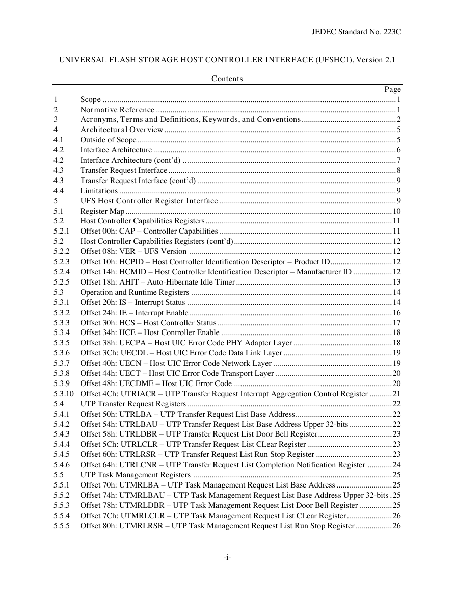
JEDEC Standard No. 223C UNIVERSAL FLASH STORAGE HOST CONTROLLER INTERFACE (UFSHCI), Version 2.1 Contents Page Scope ............................................................................................................................................... 1 1 Normative Reference ..................................................................................................................... 1 2 Acronyms, Terms and Definitions, Keywords, and Conventions .............................................. 2 3 Architectural Overview ................................................................................................................. 5 4 Outside of Scope .............................................................................................................................. 5 4.1 Interface Architecture ...................................................................................................................... 6 4.2 Interface Architecture (cont’d) ........................................................................................................ 7 4.2 Transfer Request Interface ............................................................................................................... 8 4.3 Transfer Request Interface (cont’d) ................................................................................................. 9 4.3 Limitations ....................................................................................................................................... 9 4.4 UFS Host Controller Register Interface ...................................................................................... 9 5 Register Map .................................................................................................................................. 10 5.1 5.2 Host Controller Capabilities Registers ........................................................................................... 11 5.2.1 Offset 00h: CAP – Controller Capabilities .................................................................................... 11 5.2 Host Controller Capabilities Registers (cont’d) ............................................................................. 12 5.2.2 Offset 08h: VER – UFS Version ................................................................................................... 12 5.2.3 Offset 10h: HCPID – Host Controller Identification Descriptor – Product ID .............................. 12 5.2.4 Offset 14h: HCMID – Host Controller Identification Descriptor – Manufacturer ID ................... 12 5.2.5 Offset 18h: AHIT – Auto-Hibernate Idle Timer ............................................................................ 13 5.3 Operation and Runtime Registers .................................................................................................. 14 5.3.1 Offset 20h: IS – Interrupt Status .................................................................................................... 14 5.3.2 Offset 24h: IE – Interrupt Enable ................................................................................................... 16 5.3.3 Offset 30h: HCS – Host Controller Status ..................................................................................... 17 5.3.4 Offset 34h: HCE – Host Controller Enable ................................................................................... 18 5.3.5 Offset 38h: UECPA – Host UIC Error Code PHY Adapter Layer ................................................ 18 5.3.6 Offset 3Ch: UECDL – Host UIC Error Code Data Link Layer ..................................................... 19 5.3.7 Offset 40h: UECN – Host UIC Error Code Network Layer .......................................................... 19 5.3.8 Offset 44h: UECT – Host UIC Error Code Transport Layer ......................................................... 20 5.3.9 Offset 48h: UECDME – Host UIC Error Code ............................................................................. 20 5.3.10 Offset 4Ch: UTRIACR – UTP Transfer Request Interrupt Aggregation Control Register ........... 21 5.4 UTP Transfer Request Registers .................................................................................................... 22 5.4.1 Offset 50h: UTRLBA – UTP Transfer Request List Base Address ............................................... 22 5.4.2 Offset 54h: UTRLBAU – UTP Transfer Request List Base Address Upper 32-bits ..................... 22 5.4.3 Offset 58h: UTRLDBR – UTP Transfer Request List Door Bell Register .................................... 23 5.4.4 Offset 5Ch: UTRLCLR – UTP Transfer Request List CLear Register ......................................... 23 5.4.5 Offset 60h: UTRLRSR – UTP Transfer Request List Run Stop Register ..................................... 23 5.4.6 Offset 64h: UTRLCNR – UTP Transfer Request List Completion Notification Register ............ 24 5.5 UTP Task Management Registers ................................................................................................. 25 5.5.1 Offset 70h: UTMRLBA – UTP Task Management Request List Base Address ........................... 25 5.5.2 Offset 74h: UTMRLBAU – UTP Task Management Request List Base Address Upper 32-bits . 25 5.5.3 Offset 78h: UTMRLDBR – UTP Task Management Request List Door Bell Register ................ 25 5.5.4 Offset 7Ch: UTMRLCLR – UTP Task Management Request List CLear Register ...................... 26 5.5.5 Offset 80h: UTMRLRSR – UTP Task Management Request List Run Stop Register .................. 26 -i-
JEDEC Standard No. 223B Contents (cont'd) Page 5.6 UIC Command Registers ............................................................................................................... 27 5.6.1 Offset 90h: UICCMD – UIC Command ........................................................................................ 27 5.6.2 Offset 94h: UICCMDARG1 – UIC Command Argument 1 ......................................................... 28 5.6.3 Offset 98h: UICCMDARG2 – UIC Command Argument 2 ......................................................... 29 5.6.4 Offset 9Ch: UICCMDARG3 – UIC Command Argument 3 ......................................................... 30 5.6.5 Attributes for Local L2 Timers ...................................................................................................... 30 5.7 Vendor Specific Registers .............................................................................................................. 31 5.7.1 Offset C0h to FFh: VS – Vendor Specific ..................................................................................... 31 5.8 Crypto Registers ............................................................................................................................ 32 5.8.1 Offset 100h: CCAP – Crypto Capability ....................................................................................... 32 x-CRYPTOCAP – Crypto Capability X ........................................................................................ 33 5.8.2 x-CRYPTOCFG – Crypto Configuration X .................................................................................. 34 5.8.3 6 Data structures ............................................................................................................................. 36 6.1 UTP Transfer Request List ............................................................................................................ 36 6.1.1 UTP Transfer Request Descriptor .................................................................................................. 36 6.1.2 UTP Command Descriptor ............................................................................................................ 40 6.2 UTP Task Management Request List ............................................................................................ 42 6.2.1 UTP Task Management Request Descriptor .................................................................................. 42 6.3 Key Organization for Cryptographic Algorithms .......................................................................... 44 6.3.1 AES-XTS ....................................................................................................................................... 44 6.3.2 Bitlocker-AES-CBC ...................................................................................................................... 46 6.3.3 AES-ECB ....................................................................................................................................... 47 6.3.4 ESSIV-AES-CBC .......................................................................................................................... 48 7 Theory of Operation .................................................................................................................... 48 7.1 Host Controller Configuration and Control ................................................................................... 49 7.1.1 Host Controller Initialization ......................................................................................................... 49 7.1.2 Configuration and control .............................................................................................................. 51 7.1.3 CRYPTOCFG Configuration Procedure ....................................................................................... 51 7.2 Data Transfer Operation ................................................................................................................ 52 7.2.1 Basic Steps when Building a UTP Transfer Request ..................................................................... 53 7.2.2 UPIU Processing ............................................................................................................................ 54 7.2.3 Processing UTP Transfer Request Completion ............................................................................. 56 7.3 Task Management Function ........................................................................................................... 58 7.3.1 Basic Steps when Building a UTP Task Management Request ..................................................... 58 7.3.2 Processing UTP Task Management Completion ........................................................................... 58 UIC Power Mode Change .............................................................................................................. 59 7.4 7.5 UFSHCI Internal Rules .................................................................................................................. 61 7.5.1 Command Processing Order .......................................................................................................... 61 7.5.2 RTT Processing Rules.................................................................................................................... 62 7.5.3 Data Unit Processing Order for Cryptographic operations ............................................................ 62 Error reporting and handling ..................................................................................................... 63 8 8.1 Error Types .................................................................................................................................... 63 8.1.1 System Bus Error ........................................................................................................................... 63 8.1.2 UIC Error ....................................................................................................................................... 63 -ii-
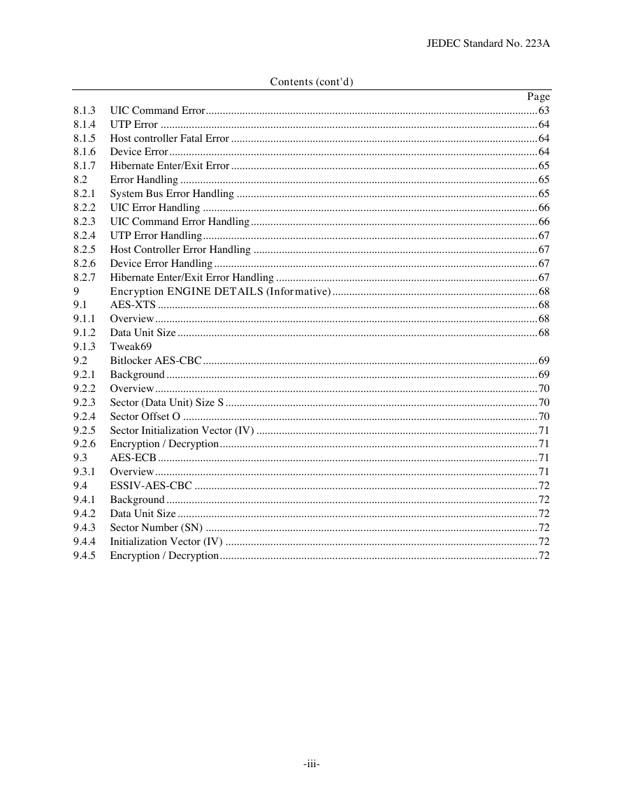
JEDEC Standard No. 223A Contents (cont'd) Page 8.1.3 UIC Command Error...................................................................................................................... 63 8.1.4 UTP Error ...................................................................................................................................... 64 8.1.5 Host controller Fatal Error ............................................................................................................. 64 8.1.6 Device Error ................................................................................................................................... 64 8.1.7 Hibernate Enter/Exit Error ............................................................................................................. 65 8.2 Error Handling ............................................................................................................................... 65 8.2.1 System Bus Error Handling ........................................................................................................... 65 8.2.2 UIC Error Handling ....................................................................................................................... 66 8.2.3 UIC Command Error Handling ...................................................................................................... 66 8.2.4 UTP Error Handling ....................................................................................................................... 67 8.2.5 Host Controller Error Handling ..................................................................................................... 67 8.2.6 Device Error Handling ................................................................................................................... 67 8.2.7 Hibernate Enter/Exit Error Handling ............................................................................................. 67 9 Encryption ENGINE DETAILS (Informative) ......................................................................... 68 9.1 AES-XTS ....................................................................................................................................... 68 9.1.1 Overview ........................................................................................................................................ 68 9.1.2 Data Unit Size ................................................................................................................................ 68 9.1.3 Tweak 69 9.2 Bitlocker AES-CBC ....................................................................................................................... 69 9.2.1 Background .................................................................................................................................... 69 9.2.2 Overview ........................................................................................................................................ 70 9.2.3 Sector (Data Unit) Size S ............................................................................................................... 70 9.2.4 Sector Offset O .............................................................................................................................. 70 9.2.5 Sector Initialization Vector (IV) .................................................................................................... 71 9.2.6 Encryption / Decryption ................................................................................................................. 71 9.3 AES-ECB ....................................................................................................................................... 71 9.3.1 Overview ........................................................................................................................................ 71 9.4 ESSIV-AES-CBC .......................................................................................................................... 72 9.4.1 Background .................................................................................................................................... 72 9.4.2 Data Unit Size ................................................................................................................................ 72 9.4.3 Sector Number (SN) ...................................................................................................................... 72 9.4.4 Initialization Vector (IV) ............................................................................................................... 72 9.4.5 Encryption / Decryption ................................................................................................................. 72 -iii-
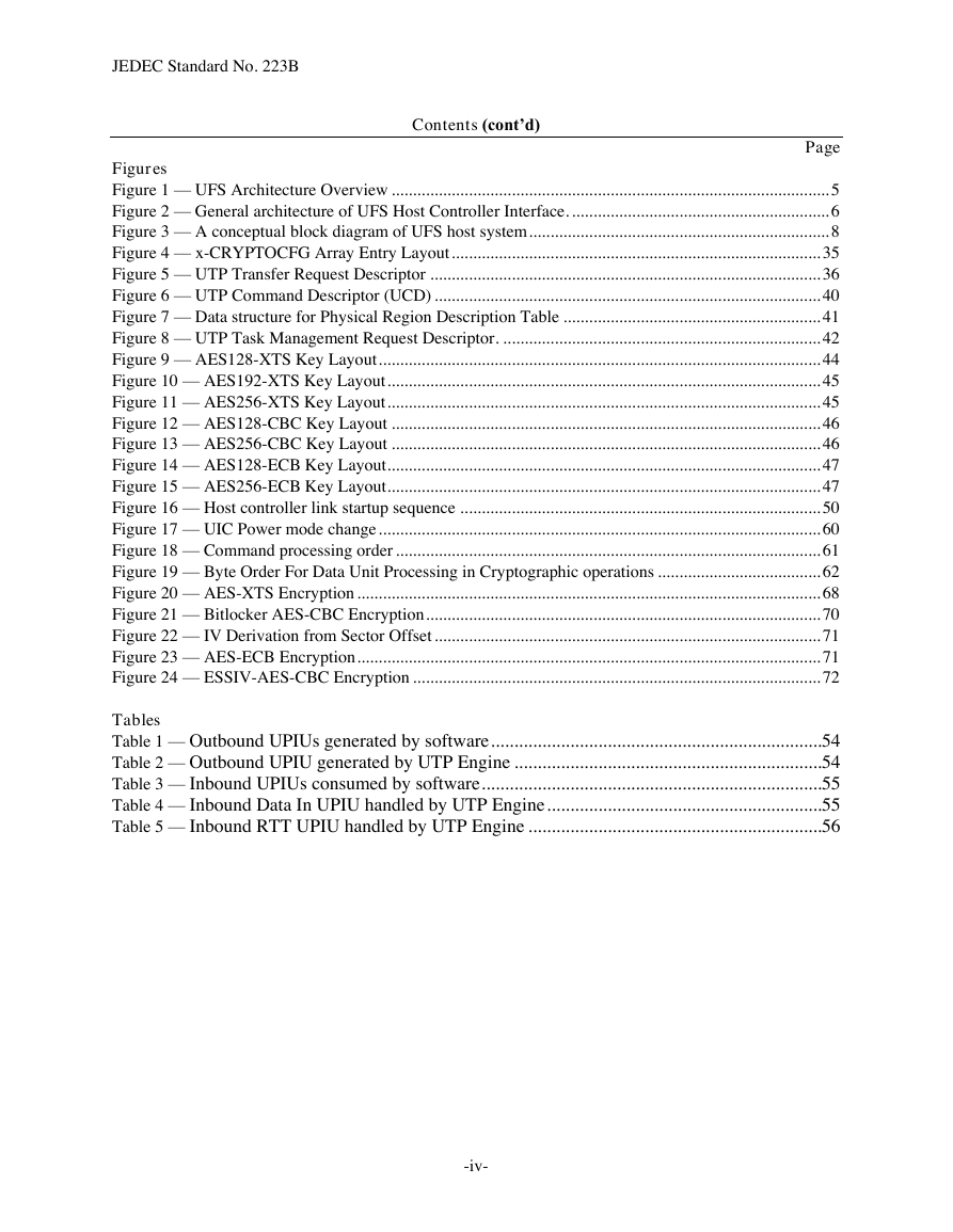
JEDEC Standard No. 223B Contents (cont’d) Page Figures Figure 1 — UFS Architecture Overview ...................................................................................................... 5 Figure 2 — General architecture of UFS Host Controller Interface. ............................................................ 6 Figure 3 — A conceptual block diagram of UFS host system ...................................................................... 8 Figure 4 –– x-CRYPTOCFG Array Entry Layout ...................................................................................... 35 Figure 5 — UTP Transfer Request Descriptor ........................................................................................... 36 Figure 6 — UTP Command Descriptor (UCD) .......................................................................................... 40 Figure 7 — Data structure for Physical Region Description Table ............................................................ 41 Figure 8 — UTP Task Management Request Descriptor. .......................................................................... 42 Figure 9 — AES128-XTS Key Layout ....................................................................................................... 44 Figure 10 — AES192-XTS Key Layout ..................................................................................................... 45 Figure 11 — AES256-XTS Key Layout ..................................................................................................... 45 Figure 12 — AES128-CBC Key Layout .................................................................................................... 46 Figure 13 — AES256-CBC Key Layout .................................................................................................... 46 Figure 14 — AES128-ECB Key Layout ..................................................................................................... 47 Figure 15 — AES256-ECB Key Layout ..................................................................................................... 47 Figure 16 — Host controller link startup sequence .................................................................................... 50 Figure 17 — UIC Power mode change ....................................................................................................... 60 Figure 18 — Command processing order ................................................................................................... 61 Figure 19 — Byte Order For Data Unit Processing in Cryptographic operations ...................................... 62 Figure 20 — AES-XTS Encryption ............................................................................................................ 68 Figure 21 — Bitlocker AES-CBC Encryption ............................................................................................ 70 Figure 22 — IV Derivation from Sector Offset .......................................................................................... 71 Figure 23 — AES-ECB Encryption ............................................................................................................ 71 Figure 24 — ESSIV-AES-CBC Encryption ............................................................................................... 72 Tables Table 1 — Outbound UPIUs generated by software .......................................................................54 Table 2 — Outbound UPIU generated by UTP Engine ..................................................................54 Table 3 — Inbound UPIUs consumed by software .........................................................................55 Table 4 — Inbound Data In UPIU handled by UTP Engine ...........................................................55 Table 5 — Inbound RTT UPIU handled by UTP Engine ...............................................................56 -iv-
分享到:
收藏