logo资料库

optisystem用户手册.pdf

第1页 / 共710页
第2页 / 共710页
第3页 / 共710页
第4页 / 共710页
第5页 / 共710页
第6页 / 共710页
第7页 / 共710页
第8页 / 共710页
资料共710页,剩余部分请下载后查看
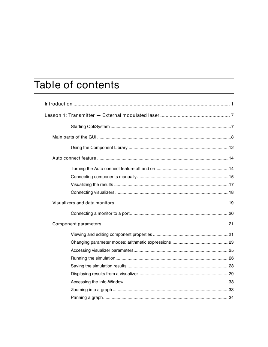
Table of contents
Introduction
Tutorials
Advanced simulation project sections
IMPORTANT
Notes
Notes:
Lesson 1: Transmitter — External modulated laser
Main parts of the GUI
Project layout
Dockers
Status Bar
Menu bar
Auto connect feature
Visualizing the results
Visualizers and data monitors
Component parameters
Display parameters in the layout
Parameter units
Info-Window
Zoom, Pan, and Trace tools
Lesson 2: Subsystems — Hierarchical simulation
Subsystem properties — name and icon
Component Library
Lesson 3: Optical Systems — WDM Design
Global parameters
Transmitters
Parameter groups
Fiber + EDFA spans
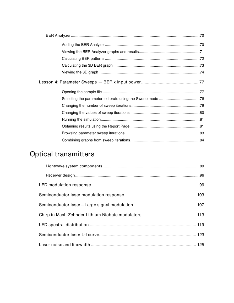
BER Analyzer
Notes:
Lesson 4: Parameter Sweeps — BER x Input power
Optical transmitters
Notes:
Lightwave system components
Optical transmitters
Communication channel
Optical receivers
Receiver design
LED modulation response
References
Semiconductor laser modulation response
References
Semiconductor laser—Large signal modulation
References:
Chirp in Mach-Zehnder Lithium Niobate modulators
References:
LED spectral distribution
References
Semiconductor laser L-I curve
Laser noise and linewidth
Notes:
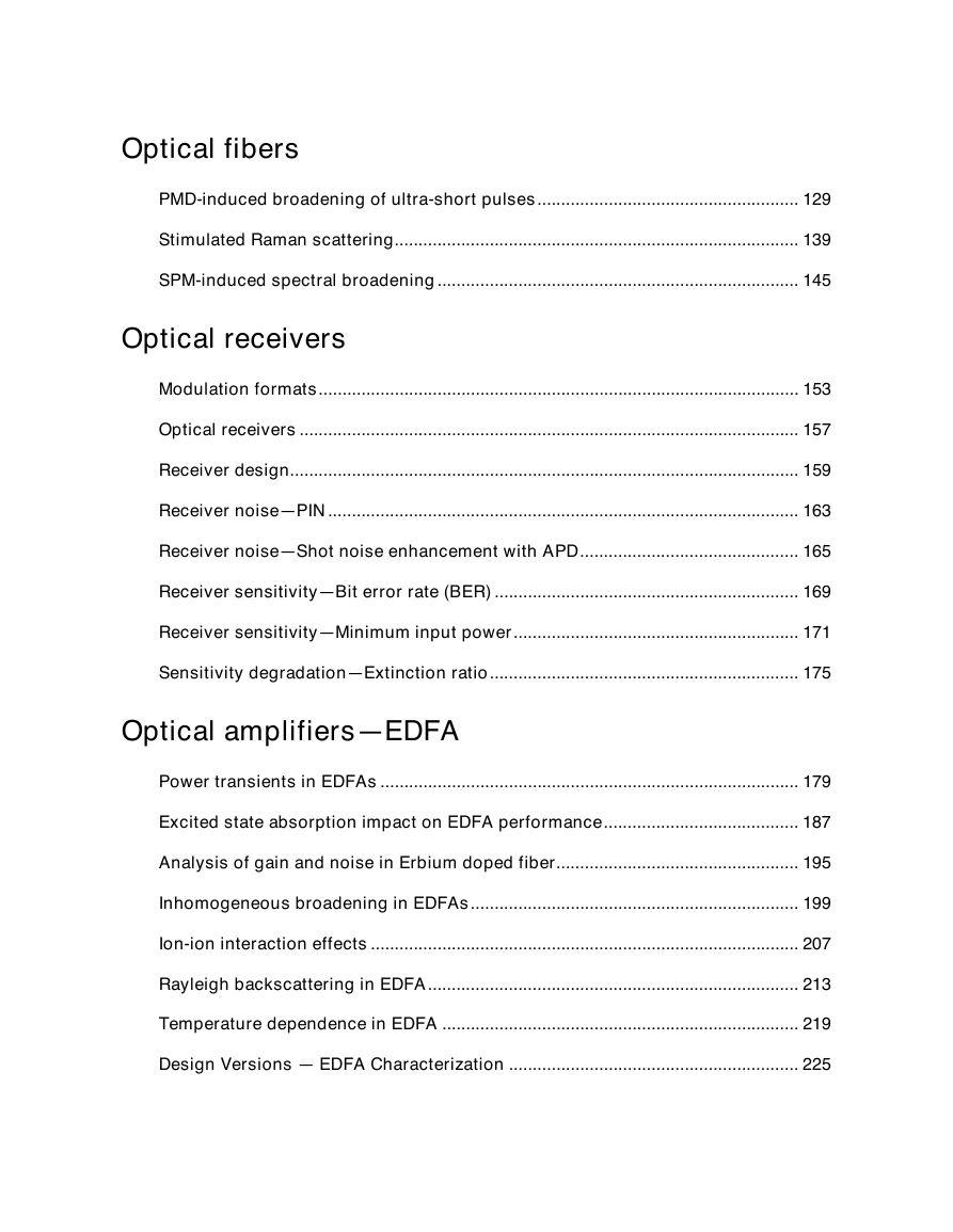
Optical fibers
Notes:
PMD-induced broadening of ultra-short pulses
References:
Stimulated Raman scattering
References
SPM-induced spectral broadening
References:
Optical receivers
Notes:
Modulation formats
Notes:
Optical receivers
Receiver design
Notes:
Receiver noise—PIN
Receiver noise—Shot noise enhancement with APD
Notes:
Receiver sensitivity—Bit error rate (BER)
Receiver sensitivity—Minimum input power
Notes:
Sensitivity degradation—Extinction ratio
Optical amplifiers—EDFA
Notes:
Power transients in EDFAs
References:
Excited state absorption impact on EDFA performance
References:
Analysis of gain and noise in Erbium doped fiber
Reference:
Inhomogeneous broadening in EDFAs
References
Notes:
Ion-ion interaction effects
Homogeneous Upconversion
Pair-Induced Quenching
References:
Rayleigh backscattering in EDFA
References:
Temperature dependence in EDFA
References:
Design Versions — EDFA Characterization
SPO optimization—System margin
SPO optimization—EDFA fiber length
Notes:
EDFA — Basic concepts
Layout Gain Spectrum
Layout Gain Saturation
Layout Amplifier Noise
Notes:
Booster Amplifier
Notes:
Inline Amplifier
Notes:
Preamplifier
Pumping requirements
Raman amplifiers
Notes:
100 nm bandwidth flatgain Raman amplifier— Average power model
References:
Raman Amplifier - Dynamic Model
Reference:
Notes:
Hybrid
Design of a broadband Raman amplifier using subsystems
Definition of Multi-line source
Defining of Multi-line source subsystem
Designing a broadband gain-flattened Raman amplifier
Using the interactive 3D graphics
SOA amplifiers
Notes
SOA gain saturation—Gaussian pulses
References
SOA gain saturation—Comparison with experimental results
References
SOA gain saturation—Chirped and super Gaussian pulses
Saturation of amplification of chirped Gaussian pulse
Saturation of amplification of super Gaussian pulse
References
SOA Gaussian Pulse — Gain Recovery
SOA parameters
The partial gain recovery
The complete gain recovery (the quasi CW operation)
Appearance of gain-saturation induced self-phase modulation
References
SOA Pulse Compression
References
Notes
SOA as a Wavelength Converter (FWM)
References
SOA as a Wavelength Converter (XGM)
References
Notes
SOA In-line Amplifier
References
Waveguide amplifiers
Notes:
Improved gain gharacteristics in high- concentration Er3+/Yb3+ codoped glass waveguide amplifiers
References
Notes:
Dispersion management
Notes:
Dispersion compensation schemes—a system perspective
Pre-, post-, and symmetrical-compensation by using DCF
Dispersion compensation by using DCM
References:
Compensation of dispersion with ideal dispersion component
Compensation of dispersion with Fiber Bragg Grating component
Notes:
Uniform Fiber Bragg Grating as a filter
References
Compensation of dispersion with OptiGratings
References
Dispersion compensation using subsystems and scripting
Lightwave systems
Notes:
Optimizing the power and dispersion compensation for nonlinear RZ transmission
References:
Limitations on the bit rate
Optical sources with a small spectral width
Optical sources with a large spectral width
References
10 Gb/s single channel transmission in standard mode fibers (SMF)
References
40 Gb/s single channel transmission in standard mode fibers (SMF)
References:
Engineering the fiber nonlinearities and dispersion
Single channel system
Multi-channel system
References
System design — Power budget
Time Division Multiplexing (TDM)
Preamplifier system
Booster system
WDM systems
Notes:
WDM Components—Tunable filters
Fabry-Perot filters
Uniform FBG Filters
WDM components—AWG demultiplexer
Notes:
Broadcast star coupler
Optical cross-connects
Notes:
Time division multiplexing
Notes:
Solitons and soliton systems
Solitons
Soliton systems
Notes:
Fundamental and higher order solitons
Reference
Interactions of optical solitons
Reference:
Decay of higher order solitons in the presence of intrapulse Raman scattering
Reference:
Orthogonal Raman gain
References
Stability of solitons in birefringent optical fibers
References:
Influence of third-order dispersion on solitons
References
Average soliton regime
References
Metro systems
Notes:
Interchannel crosstalk in Metro networks
References:
Migrating to 10Gbps in Metro networks
No dispersion compensation
"Per span" dispersion compensation
"Lumped" dispersion compensation
References
Negative dispersion fiber for Metro networks
Modeling Directly Modulated Lasers
Transmission Characteristics of DMLs
Transmission at higher bit rates
32 Channel DWDM system simulation at 2.5 Gbps
References
Power level management in optical Metro networks
Design without amplification
Self-Phase Modulation
Cross-Phase Modulation
Four-Wave Mixing
Design with Lumped Amplification
Optical Amplifier
Unity Gain Design
Considering the Non-Ideal Characteristics of EDFAs
References:
WDM Ring—Wavelength independent subscriber equipment
References
OptiSystem Tutorials Optical Communication System Design Software Version 3.0 for Windows® 2000/XP
OptiSystem Tutorials Optical Communication System Design Software Copyright © 2003 Optiwave Corporation All rights reserved. All OptiSystem documents, including this one, and the information contained therein, is copyright material. No part of this document may be reproduced, stored in a retrieval system, or transmitted in any form or by any means whatsoever, including recording, photocopying, or faxing, without prior written approval of Optiwave Corporation. Disclaimer Optiwave Corporation makes no representation or warranty with respect to the adequacy of this documentation or the programs which it describes for any particular purpose or with respect to its adequacy to produce any particular result. In no event shall Optiwave Corporation, its employees, its contractors or the authors of this documentation, be liable for special, direct, indirect, or consequential damages, losses, costs, charges, claims, demands, or claim for lost profits, fees, or expenses of any nature or kind. 10/1/03
Table of contents Introduction ..................................................................................................................... 1 Lesson 1: Transmitter — External modulated laser .................................................... 7 Starting OptiSystem ...................................................................................................7 Main parts of the GUI ..............................................................................................................8 Using the Component Library ..................................................................................12 Auto connect feature ............................................................................................................14 Turning the Auto connect feature off and on............................................................14 Connecting components manually ...........................................................................15 Visualizing the results ..............................................................................................17 Connecting visualizers .............................................................................................18 Visualizers and data monitors .............................................................................................19 Connecting a monitor to a port.................................................................................20 Component parameters........................................................................................................21 Viewing and editing component properties ..............................................................21 Changing parameter modes: arithmetic expressions...............................................23 Accessing visualizer parameters..............................................................................25 Running the simulation.............................................................................................26 Saving the simulation results ...................................................................................28 Displaying results from a visualizer..........................................................................29 Accessing the Info-Window......................................................................................33 Zooming into a graph ...............................................................................................33 Panning a graph.......................................................................................................34
Tracing a graph ........................................................................................................34 Saving graphs ..........................................................................................................35 Lesson 2: Subsystems — Hierarchical simulation.................................................... 37 Loading a sample file ...............................................................................................37 Creating a subsystem ..............................................................................................38 Looking inside a subsystem .....................................................................................38 Creating a subsystem output port ............................................................................40 Connecting a component output port to a subsystem output port............................40 Changing the port position and location...................................................................41 Subsystem properties — name and icon............................................................................43 Changing a subsystem name...................................................................................43 Adding a subsystem icon .........................................................................................44 Adding global parameters to a subsystem ...............................................................45 Accessing global parameters ...................................................................................47 Component Library ...............................................................................................................50 Creating sub folders in the Custom Library..............................................................50 Adding a component to the library ...........................................................................52 Creating additional ports ..........................................................................................52 Adding a fork to the subsystem................................................................................53 Saving the modified subsystem ...............................................................................55 Running the External Modulated Transmitter simulation .........................................55 Lesson 3: Optical Systems — WDM Design............................................................... 57 Viewing the global parameters.................................................................................57 Accessing the Parameter groups table ....................................................................60 Testing the transmitter .............................................................................................62 Connecting the Loop Control ...................................................................................64 Setting the number of signal round trips ..................................................................65 Obtaining results after the demultiplexer..................................................................66 Adding a receiver .....................................................................................................68
BER Analyzer.........................................................................................................................70 Adding the BER Analyzer.........................................................................................70 Viewing the BER Analyzer graphs and results.........................................................71 Calculating BER patterns .........................................................................................72 Calculating the 3D BER graph .................................................................................73 Viewing the 3D graph...............................................................................................74 Lesson 4: Parameter Sweeps — BER x Input power................................................. 77 Opening the sample file ...........................................................................................77 Selecting the parameter to iterate using the Sweep mode ......................................78 Changing the number of sweep iterations................................................................79 Changing the values of sweep iterations .................................................................80 Running the simulation.............................................................................................81 Obtaining results using the Report Page .................................................................81 Browsing parameter sweep iterations ......................................................................83 Combining graphs from sweep iterations.................................................................84 Optical transmitters Lightwave system components...........................................................................................89 Receiver design.....................................................................................................................96 LED modulation response............................................................................................ 99 Semiconductor laser modulation response ............................................................. 103 Semiconductor laser—Large signal modulation ..................................................... 107 Chirp in Mach-Zehnder Lithium Niobate modulators .............................................. 113 LED spectral distribution ........................................................................................... 119 Semiconductor laser L-I curve................................................................................... 123 Laser noise and linewidth .......................................................................................... 125
Optical fibers PMD-induced broadening of ultra-short pulses....................................................... 129 Stimulated Raman scattering..................................................................................... 139 SPM-induced spectral broadening............................................................................ 145 Optical receivers Modulation formats..................................................................................................... 153 Optical receivers ......................................................................................................... 157 Receiver design........................................................................................................... 159 Receiver noise—PIN ................................................................................................... 163 Receiver noise—Shot noise enhancement with APD.............................................. 165 Receiver sensitivity—Bit error rate (BER) ................................................................ 169 Receiver sensitivity—Minimum input power............................................................ 171 Sensitivity degradation—Extinction ratio................................................................. 175 Optical amplifiers—EDFA Power transients in EDFAs ........................................................................................ 179 Excited state absorption impact on EDFA performance......................................... 187 Analysis of gain and noise in Erbium doped fiber................................................... 195 Inhomogeneous broadening in EDFAs..................................................................... 199 Ion-ion interaction effects .......................................................................................... 207 Rayleigh backscattering in EDFA.............................................................................. 213 Temperature dependence in EDFA ........................................................................... 219 Design Versions — EDFA Characterization ............................................................. 225
分享到:
收藏