1
2
3
4
5
6
7
8
9
10
11
12
13
14
15
16
17
18
19
20
21
22
23
24
25
26
27
28
29
30
31
32
33
34
35
36
37
38
39
40
41
42
43
44
45
46
47
48
49
50
VESA LOGO HERE
39899 Balentine Drive, Suite 125
Newark, CA 94560
Phone: 510 651 5122
Fax: 510 651 5127
URL: www.vesa.org
Proposed DisplayPort Alt
Mode on USB Type-C
Standard
Version 1, Draft 3
28 July, 2014
Purpose
The purpose of this document is to specify the use of DisplayPort as an Alternate Mode for the USB
Type-C connector.
Summary
This standard describes the use of the DisplayPort protocol between devices that support the USB Type-
C connector using USB Type-C to USB Type-C Cable Assemblies. It describes cable assemblies that
adapt the USB Type-C connector to Legacy DisplayPort connectors. It describes cable assemblies and
adapters to adapt DisplayPort on USB Type-C to other video protocols. It describes the simultaneous use
of USB Enhanced SuperSpeed and the DisplayPort protocol on the USB Type-C connector for docking
applications.
This standard describes the USB Type-C connector pin assignments and DisplayPort signaling rates to
be used in various scenarios when using the above cable assemblies and adapters. It describes how the
USB-PD Alternate Mode Discovery and Entry Processes are applied to DisplayPort on the USB Type-C
connector.
Proposed DisplayPort Alt Mode on USB Type-C
Copyright © 2014 Video Electronics Standards Association. All rights reserved.
DISTRIBUTION TO NON-MEMBERS IS PROHIBITED
V1, d3
Page 1 of 83
�
51
52
53
54
55
56
57
58
59
60
61
62
63
64
65
66
67
68
69
70
71
72
73
74
75
76
77
78
79
80
81
82
83
84
85
86
87
88
89
90
91
92
93
94
1
Contents
Purpose .......................................................................................................................................................... 1
Summary ........................................................................................................................................................ 1
Contents ........................................................................................................................................................ 2
Figures .......................................................................................................................................................... 5
Tables ............................................................................................................................................................ 6
Preface .......................................................................................................................................................... 7
Intellectual Property ................................................................................................................................. 7
Trademarks .............................................................................................................................................. 7
Patents ..................................................................................................................................................... 8
Support for this Standard ........................................................................................................................... 8
Acknowledgements ................................................................................................................................... 8
Revision History ..................................................................................................................................... 10
Introduction ........................................................................................................................................... 11
1.1 Purpose ........................................................................................................................................ 11
1.2 Scope ........................................................................................................................................... 11
1.3 Related Documents ...................................................................................................................... 12
1.4 Conventions ................................................................................................................................. 12
1.4.1 Precedence ...................................................................................................................... 12
1.4.2 Keywords ........................................................................................................................ 12
1.4.3 Numbering ...................................................................................................................... 13
1.5 Terms and Abbreviations ............................................................................................................. 13
2 Overview ............................................................................................................................................... 15
2.1
Introduction ................................................................................................................................. 15
2.2 USB Type-C Receptacles, Plugs and Cables ................................................................................. 15
2.3 Signaling and cable types ............................................................................................................. 15
2.4 Multi-Function systems ................................................................................................................ 16
3 Pin Assignments and Descriptions .......................................................................................................... 17
3.1 Pin Assignments Overview ........................................................................................................... 17
3.2 USB Type-C DisplayPort Pin Assignments ................................................................................... 18
3.2.1 Pinout Assignment support requirements ......................................................................... 19
3.3 DFP_D Pin Assignment A ............................................................................................................ 21
3.4 DFP_D Pin Assignment B ............................................................................................................ 21
3.5 DFP_D Pin Assignment C ............................................................................................................ 22
3.6 DFP_D Pin Assignment D ............................................................................................................ 23
3.7 DFP_D Pin Assignment E ............................................................................................................ 24
3.8 DFP_D Pin Assignment F............................................................................................................. 26
3.9 UFP_D Pin Assignment A ............................................................................................................ 27
3.10 UFP_D Pin Assignment B ........................................................................................................... 28
3.11 UFP_D Pin Assignment C ........................................................................................................... 28
3.12 UFP_D Pin Assignment D ........................................................................................................... 29
3.13 UFP_D Pin Assignment E ........................................................................................................... 30
3.14 USB Gen 2 PHY signaling for DisplayPort (GEN2_BR) .............................................................. 31
3.15 AUX and HPD signaling ............................................................................................................. 31
Proposed DisplayPort Alt Mode on USB Type-C
Copyright © 2014 Video Electronics Standards Association. All rights reserved.
DISTRIBUTION TO NON-MEMBERS IS PROHIBITED
V1, d3
Page 2 of 83
�
95
96
97
98
99
100
101
102
103
104
105
106
107
108
109
110
111
112
113
114
115
116
117
118
119
120
121
122
123
124
125
126
127
128
129
130
131
132
133
134
135
136
137
138
139
140
141
3.15.1 AUX signaling ............................................................................................................... 31
3.15.2 HPD signaling ................................................................................................................ 32
3.15.3 AUX and HPD schematics .............................................................................................. 32
3.16 Legacy DisplayPort Connector CONFIG1 and CONFIG2 pins ..................................................... 35
4 USB Type-C Cable Assemblies used for DisplayPort ............................................................................. 36
4.1 Scenario 1 USB Type-C Full-Featured Cable Assembly ................................................................ 36
4.1.1 Scenario 1 USB Type-C Full-Featured cable Assembly using GEN2_BR ......................... 36
4.1.2 Scenario 1 USB Type-C Full-Featured cable Assembly using DP_BR .............................. 38
4.2 Scenarios 2a and 2b USB Type-C to Legacy DisplayPort Cable Assemblies ................................. 39
4.2.1 Scenario 2a USB Type-C DFP_D to Legacy DisplayPort UFP_D ..................................... 39
4.2.2 Scenario 2b Legacy DisplayPort DFP_D to USB Type -C UFP_D ..................................... 41
4.2.3 USB Type-C to Legacy DisplayPort Cable Assembly electrical properties ....................... 43
4.2.4 USB Type-C to Legacy DisplayPort Cable Assembly functionality .................................. 46
4.3 Scenarios 3a and 3c USB Type-C DFP_D to Protocol Converter ................................................... 48
4.3.1 HDMI Protocol Converter Adapters ................................................................................. 48
4.3.2 VGA Protocol Converter Adapters ................................................................................... 49
4.3.3 DVI Protocol Converter Adapters .................................................................................... 49
4.4 Scenario 4a USB Type-C DFP_D to a Multi-Function Dock (MF Dock) ....................................... 49
4.4.1 Scenario 4a USB Type-C Full-Featured Cable Assembly using GEN2_BR Multi -Function49
4.4.2 Scenario 4a USB Type-C Full-Featured Cable Assembly using DP_BR Multi -Function ... 50
4.5 Scenario 4b USB Type-C DFP_D to a VESA DockPort adapter .................................................... 52
4.6 Scenarios 4c/d USB Type-C DFP_D to Multi-Function cradle/captive cable dock ......................... 54
4.6.1 Scenarios 4c/d USB Type-C DFP_D to Multi-Function cradle dock using GEN2_BR
Multi-Function ............................................................................................................... 54
4.6.2 Scenario 4c/d USB Type-C DFP_D to Multi-Function cradle/captive cable dock using
DP_BR Multi-Function ................................................................................................... 56
5 Discovery and USB-PD .......................................................................................................................... 57
5.1 Connection discovery ................................................................................................................... 57
5.2 DisplayPort Mode discovery and entry/exit .................................................................................. 57
5.2.1 Structured VDM Header .................................................................................................. 57
5.2.2 DisplayPort Enter Mode .................................................................................................. 60
5.2.3 DisplayPort Status Update ............................................................................................... 60
5.2.4 DisplayPort Configure ..................................................................................................... 61
5.2.5 Attention ......................................................................................................................... 63
5.2.6 DisplayPort Exit Mode .................................................................................................... 63
5.3 VDM Message flows .................................................................................................................... 64
6 Miscellaneous ........................................................................................................................................ 75
6.1 VCONN and VBUS ........................................................................................................................ 75
6.2 Low power operation ................................................................................................................... 75
6.3 Equivalent USB Functionality ...................................................................................................... 75
A DisplayPort Alternate Mode Examples .................................................................................................. 76
A.1. Purpose ....................................................................................................................................... 76
A.1.1. DisplayPort Alternate Mode Examples ........................................................................... 76
A.2. USB Type-C USB Host to DisplayPort Video Adapter Example .................................................. 76
A.2.1. DisplayPort Video Adapter Assumptions ........................................................................ 76
A.2.2. Block Diagrams .............................................................................................................. 77
A.2.3. Solution ......................................................................................................................... 78
Proposed DisplayPort Alt Mode on USB Type-C
Copyright © 2014 Video Electronics Standards Association. All rights reserved.
DISTRIBUTION TO NON-MEMBERS IS PROHIBITED
V1, d3
Page 3 of 83
�
142
143
144
145
146
A.3. USB Dock with DisplayPort Example .......................................................................................... 80
A.3.1. USB Dock with DisplayPort Assumptions ...................................................................... 80
A.3.2. Block Diagrams .............................................................................................................. 81
A.3.3. Solution ......................................................................................................................... 81
Proposed DisplayPort Alt Mode on USB Type-C
Copyright © 2014 Video Electronics Standards Association. All rights reserved.
DISTRIBUTION TO NON-MEMBERS IS PROHIBITED
V1, d3
Page 4 of 83
�
147
148
149
150
151
152
153
154
155
156
157
158
159
160
161
162
163
164
165
166
167
168
169
170
171
172
173
174
175
176
177
178
179
180
181
182
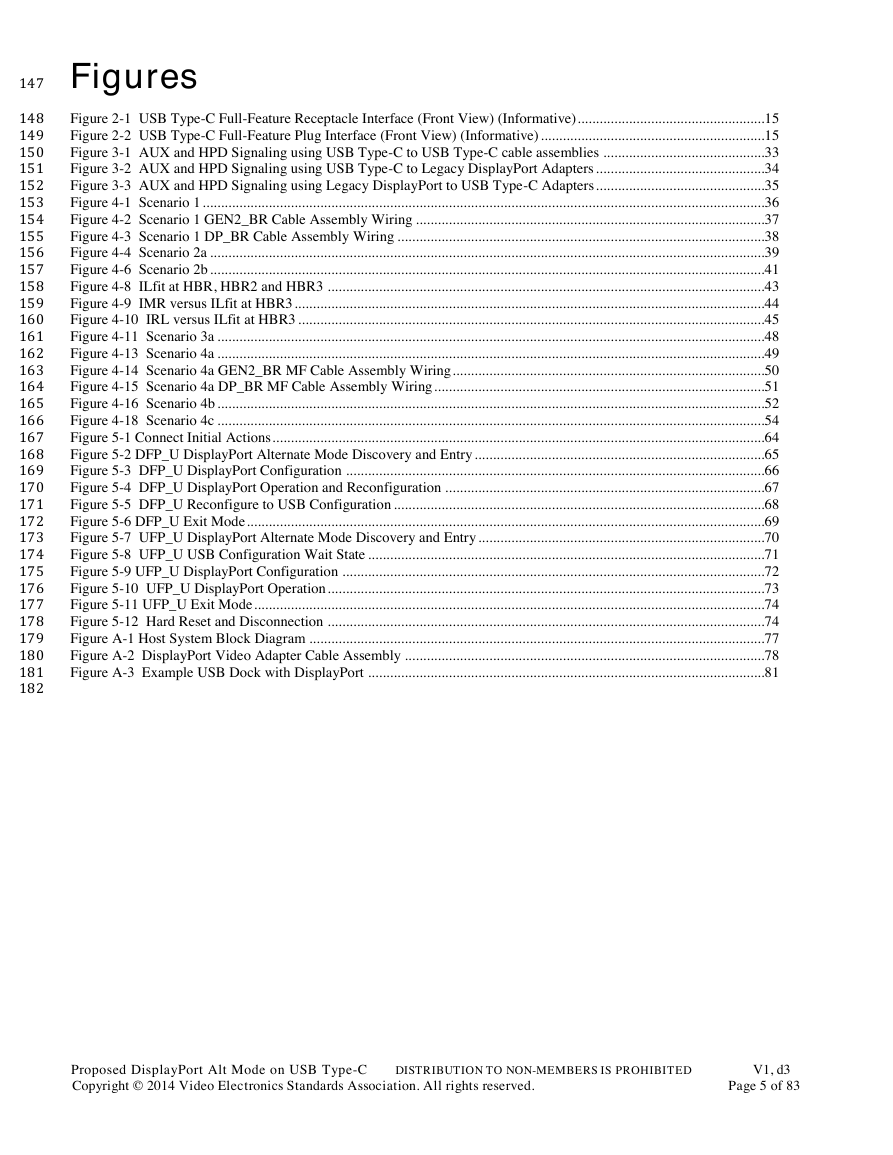
Figures
Figure 2-1 USB Type-C Full-Feature Receptacle Interface (Front View) (Informative) ................................................... 15
Figure 2-2 USB Type-C Full-Feature Plug Interface (Front View) (Informative) ............................................................. 15
Figure 3-1 AUX and HPD Signaling using USB Type-C to USB Type-C cable assemblies ............................................ 33
Figure 3-2 AUX and HPD Signaling using USB Type-C to Legacy DisplayPort Adapters .............................................. 34
Figure 3-3 AUX and HPD Signaling using Legacy DisplayPort to USB Type-C Adapters .............................................. 35
Figure 4-1 Scenario 1 ......................................................................................................................................................... 36
Figure 4-2 Scenario 1 GEN2_BR Cable Assembly Wiring ............................................................................................... 37
Figure 4-3 Scenario 1 DP_BR Cable Assembly Wiring .................................................................................................... 38
Figure 4-4 Scenario 2a ....................................................................................................................................................... 39
Figure 4-6 Scenario 2b ....................................................................................................................................................... 41
Figure 4-8 ILfit at HBR, HBR2 and HBR3 ....................................................................................................................... 43
Figure 4-9 IMR versus ILfit at HBR3 ................................................................................................................................ 44
Figure 4-10 IRL versus ILfit at HBR3 ............................................................................................................................... 45
Figure 4-11 Scenario 3a ..................................................................................................................................................... 48
Figure 4-13 Scenario 4a ..................................................................................................................................................... 49
Figure 4-14 Scenario 4a GEN2_BR MF Cable Assembly Wiring ..................................................................................... 50
Figure 4-15 Scenario 4a DP_BR MF Cable Assembly Wiring .......................................................................................... 51
Figure 4-16 Scenario 4b ..................................................................................................................................................... 52
Figure 4-18 Scenario 4c ..................................................................................................................................................... 54
Figure 5-1 Connect Initial Actions ...................................................................................................................................... 64
Figure 5-2 DFP_U DisplayPort Alternate Mode Discovery and Entry ............................................................................... 65
Figure 5-3 DFP_U DisplayPort Configuration .................................................................................................................. 66
Figure 5-4 DFP_U DisplayPort Operation and Reconfiguration ....................................................................................... 67
Figure 5-5 DFP_U Reconfigure to USB Configuration ..................................................................................................... 68
Figure 5-6 DFP_U Exit Mode ............................................................................................................................................. 69
Figure 5-7 UFP_U DisplayPort Alternate Mode Discovery and Entry .............................................................................. 70
Figure 5-8 UFP_U USB Configuration Wait State ............................................................................................................ 71
Figure 5-9 UFP_U DisplayPort Configuration ................................................................................................................... 72
Figure 5-10 UFP_U DisplayPort Operation ....................................................................................................................... 73
Figure 5-11 UFP_U Exit Mode ........................................................................................................................................... 74
Figure 5-12 Hard Reset and Disconnection ....................................................................................................................... 74
Figure A-1 Host System Block Diagram ............................................................................................................................ 77
Figure A-2 DisplayPort Video Adapter Cable Assembly .................................................................................................. 78
Figure A-3 Example USB Dock with DisplayPort ............................................................................................................ 81
Proposed DisplayPort Alt Mode on USB Type-C
Copyright © 2014 Video Electronics Standards Association. All rights reserved.
DISTRIBUTION TO NON-MEMBERS IS PROHIBITED
V1, d3
Page 5 of 83
�
183
184
185
186
187
188
189
190
191
192
193
194
195
196
197
198
199
200
201
202
203
204
205
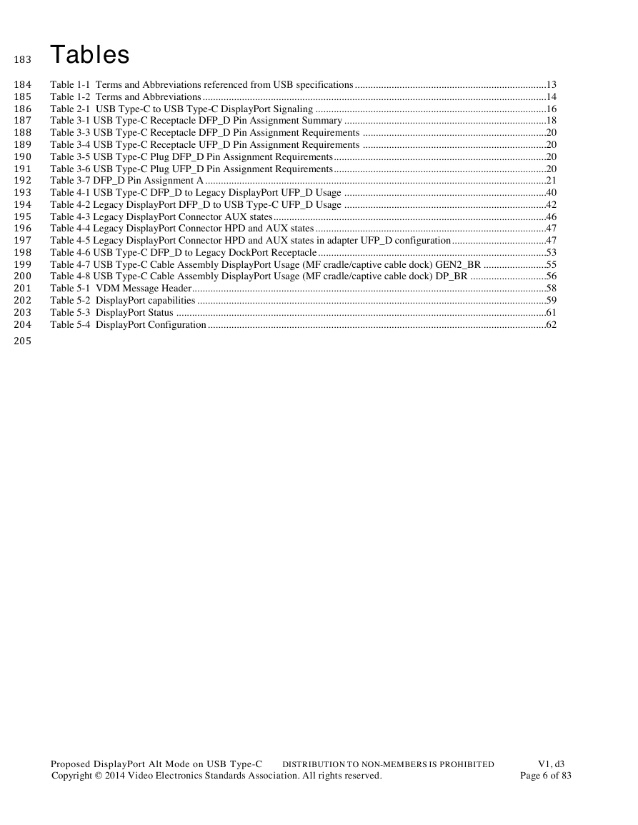
Tables
Table 1-1 Terms and Abbreviations referenced from USB specifications ......................................................................... 13
Table 1-2 Terms and Abbreviations ................................................................................................................................... 14
Table 2-1 USB Type-C to USB Type-C DisplayPort Signaling ........................................................................................ 16
Table 3-1 USB Type-C Receptacle DFP_D Pin Assignment Summary ............................................................................. 18
Table 3-3 USB Type-C Receptacle DFP_D Pin Assignment Requirements ...................................................................... 20
Table 3-4 USB Type-C Receptacle UFP_D Pin Assignment Requirements ...................................................................... 20
Table 3-5 USB Type-C Plug DFP_D Pin Assignment Requirements................................................................................. 20
Table 3-6 USB Type-C Plug UFP_D Pin Assignment Requirements................................................................................. 20
Table 3-7 DFP_D Pin Assignment A .................................................................................................................................. 21
Table 4-1 USB Type-C DFP_D to Legacy DisplayPort UFP_D Usage ............................................................................. 40
Table 4-2 Legacy DisplayPort DFP_D to USB Type-C UFP_D Usage ............................................................................. 42
Table 4-3 Legacy DisplayPort Connector AUX states........................................................................................................ 46
Table 4-4 Legacy DisplayPort Connector HPD and AUX states ........................................................................................ 47
Table 4-5 Legacy DisplayPort Connector HPD and AUX states in adapter UFP_D configuration .................................... 47
Table 4-6 USB Type-C DFP_D to Legacy DockPort Receptacle ....................................................................................... 53
Table 4-7 USB Type-C Cable Assembly DisplayPort Usage (MF cradle/captive cable dock) GEN2_BR ........................ 55
Table 4-8 USB Type-C Cable Assembly DisplayPort Usage (MF cradle/captive cable dock) DP_BR ............................. 56
Table 5-1 VDM Message Header....................................................................................................................................... 58
Table 5-2 DisplayPort capabilities ..................................................................................................................................... 59
Table 5-3 DisplayPort Status ............................................................................................................................................. 61
Table 5-4 DisplayPort Configuration ................................................................................................................................. 62
Proposed DisplayPort Alt Mode on USB Type-C
Copyright © 2014 Video Electronics Standards Association. All rights reserved.
DISTRIBUTION TO NON-MEMBERS IS PROHIBITED
V1, d3
Page 6 of 83
�
206
207
208
209
210
211
212
213
214
215
216
217
218
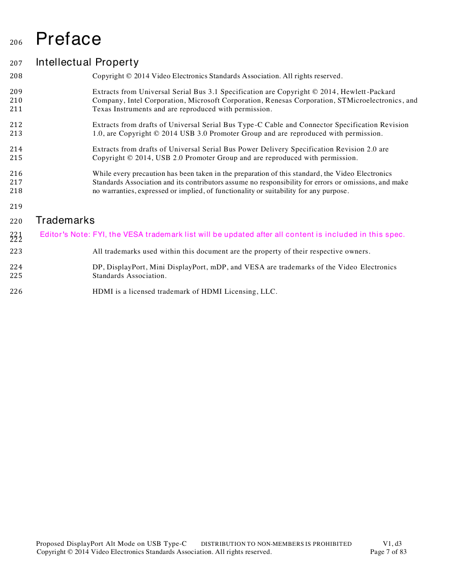
Preface
Intellectual Property
Copyright © 2014 Video Electronics Standards Association. All rights reserved.
Extracts from Universal Serial Bus 3.1 Specification are Copyright © 2014, Hewlett -Packard
Company, Intel Corporation, Microsoft Corporation, R enesas Corporation, STMicroelectronics, and
Texas Instruments and are reproduced with permission.
Extracts from drafts of Universal Serial Bus Type -C Cable and Connector Specification Revision
1.0, are Copyright © 2014 USB 3.0 Promoter Group and are reproduced with permission.
Extracts from drafts of Universal Serial Bus Power Delivery Specification Revision 2.0 are
Copyright © 2014, USB 2.0 Promoter Group and are reproduced with permission.
While every precaution has been taken in the preparation of this standard, the Video Electronics
Standards Association and its contributors assume no responsibility for errors or omissions, and make
no warranties, expressed or implied, of functionality or suitability for any purpose.
219
220
221
222
223
224
225
226
Trademarks
Editor’s Note: FYI, the VESA trademark list will be updated after all content is included in this spec.
All trademarks used within this document are the property of their respective owners.
DP, DisplayPort, Mini DisplayPort, mDP, and VESA are trademarks of the Video Electronics
Standards Association.
HDMI is a licensed trademark of HDMI Licensing, LLC.
Proposed DisplayPort Alt Mode on USB Type-C
Copyright © 2014 Video Electronics Standards Association. All rights reserved.
DISTRIBUTION TO NON-MEMBERS IS PROHIBITED
V1, d3
Page 7 of 83
�
227
228
229
230
231
232
233
234
235
236
237
238
239
240
241
242
243
244
245
246
247
248
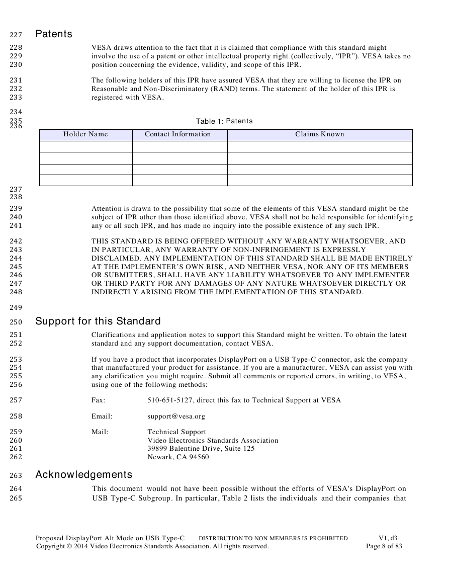
Patents
VESA draws attention to the fact that it is claimed that compliance with this standard might
involve the use of a patent or other intellectual property right (collectively, “IPR”). VESA takes no
position concerning the evidence, validity, and scope of this IPR.
The following holders of this IPR have assured VESA that they are willing to license the IPR on
Reasonable and Non-Discriminatory (RAND) terms. The statement of the holder of this IPR is
registered with VESA.
Holder Name
Contact Information
Claims Known
Table 1: Patents
Attention is drawn to the possibility that some of the elements of this VESA standard might be the
subject of IPR other than those identified above. VESA shall not be held responsible for identifying
any or all such IPR, and has made no inquiry into the possible existence of any such IPR.
THIS STANDARD IS BEING OFFERED WITHOUT ANY WARRANTY WHATSOEVER, AND
IN PARTICULAR, ANY WARRANTY OF NON-INFRINGEMENT IS EXPRESSLY
DISCLAIMED. ANY IMPLEMENTATION OF THIS STANDARD SHALL BE MADE ENTIRELY
AT THE IMPLEMENTER’S OWN RISK, AND NEITHER VESA, NOR ANY OF ITS MEMBERS
OR SUBMITTERS, SHALL HAVE ANY LIABILITY WHATSOEVER TO ANY IMPLEMENTER
OR THIRD PARTY FOR ANY DAMAGES OF ANY NATURE WHATSOEVER DIRECTLY OR
INDIRECTLY ARISING FROM THE IMPLEMENTATION OF THIS STANDARD.
249
250
251
252
253
254
255
256
257
258
259
260
261
262
263
264
265
Support for this Standard
Clarifications and application notes to support this Standard might be written. To obtain the latest
standard and any support documentation, contact VESA.
If you have a product that incorporates DisplayPort on a USB Type-C connector, ask the company
that manufactured your product for assistance. If you are a manufacturer, VESA can assist you with
any clarification you might require. Submit all comments or reported errors, in writing, to VESA,
using one of the following methods:
Fax:
510-651-5127, direct this fax to Technical Support at VESA
Email:
support@vesa.org
Mail:
Technical Support
Video Electronics Standards Association
39899 Balentine Drive, Suite 125
Newark, CA 94560
Acknowledgements
This document would not have been possible without the efforts of VESA's DisplayPort on
USB Type-C Subgroup. In particular, Table 2 lists the individuals and their companies that
Proposed DisplayPort Alt Mode on USB Type-C
Copyright © 2014 Video Electronics Standards Association. All rights reserved.
DISTRIBUTION TO NON-MEMBERS IS PROHIBITED
V1, d3
Page 8 of 83
�


 2023年江西萍乡中考道德与法治真题及答案.doc
 2012年重庆南川中考生物真题及答案.doc
 2013年江西师范大学地理学综合及文艺理论基础考研真题.doc
 2020年四川甘孜小升初语文真题及答案I卷.doc
 2020年注册岩土工程师专业基础考试真题及答案.doc
 2023-2024学年福建省厦门市九年级上学期数学月考试题及答案.doc
 2021-2022学年辽宁省沈阳市大东区九年级上学期语文期末试题及答案.doc
 2022-2023学年北京东城区初三第一学期物理期末试卷及答案.doc
 2018上半年江西教师资格初中地理学科知识与教学能力真题及答案.doc
 2012年河北国家公务员申论考试真题及答案-省级.doc
 2020-2021学年江苏省扬州市江都区邵樊片九年级上学期数学第一次质量检测试题及答案.doc
 2022下半年黑龙江教师资格证中学综合素质真题及答案.doc