THC63LVDF84B_Rev.3.30_E
THC63LVDF84B
LVDS 24Bit COLOR HOST-LCD PANEL INTERFACE RECEIVER (Falling Edge Clock)
n/a
70 to 85
15 to 20
available
available
20 to 70
available
available
available
VCC[V]
2.5 to 2.7
2.7 to 3.0
3.0 to 3.6
n/a : not available
• Falling Edge Clock
• PLL requires No external components
• Rx power consumption < 80mW @VCC 2.5V,
n/a
n/a
available
Features
• Wide dot clock and Wide VCC range:
Clock Frequency[MHz]
65MHz Grayscale
• Power-Down Mode
• Low profile 56 Lead TSSOP Package
• Pin compatible with THC63LVDF84A
General Description
The THC63LVDF84B receiver supports wide VCC
range(2.5~3.6V). At single 2.5V supply, the
THC63LVDF84B reduces EMI and power consump-
tion.
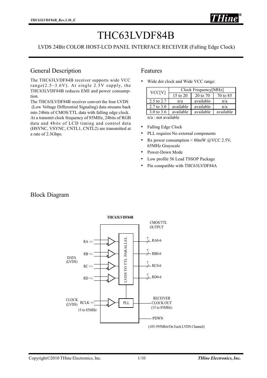
The THC63LVDF84B receiver convert the four LVDS
(Low Voltage Differential Signaling) data streams back
into 24bits of CMOS/TTL data with falling edge clock.
At a transmit clock frequency of 85MHz, 24bits of RGB
data and 4bits of LCD timing and control data
(HSYNC, VSYNC, CNTL1, CNTL2) are transmitted at
a rate of 2.3Gbps.
Block Diagram
THC63LVDF84B
DATA
(LVDS)
RA +/-
RB +/-
RC +/-
RD +/-
L
E
L
L
A
R
A
P
L
T
T
O
T
S
D
V
L
CLOCK
(LVDS)
RCLK +/-
15 to 85MHz
PLL
CMOS/TTL
OUTPUT
7
7
7
7
RA0-6
RB0-6
RC0-6
RD0-6
RECEIVER
CLOCK OUT
(15 to 85MHz)
/PDWN
(105-595Mbit/On Each LVDS Channel)
Copyright©2010 THine Electronics, Inc. 1/10 THine Electronics, Inc.
�
THC63LVDF84B_Rev.3.30_E
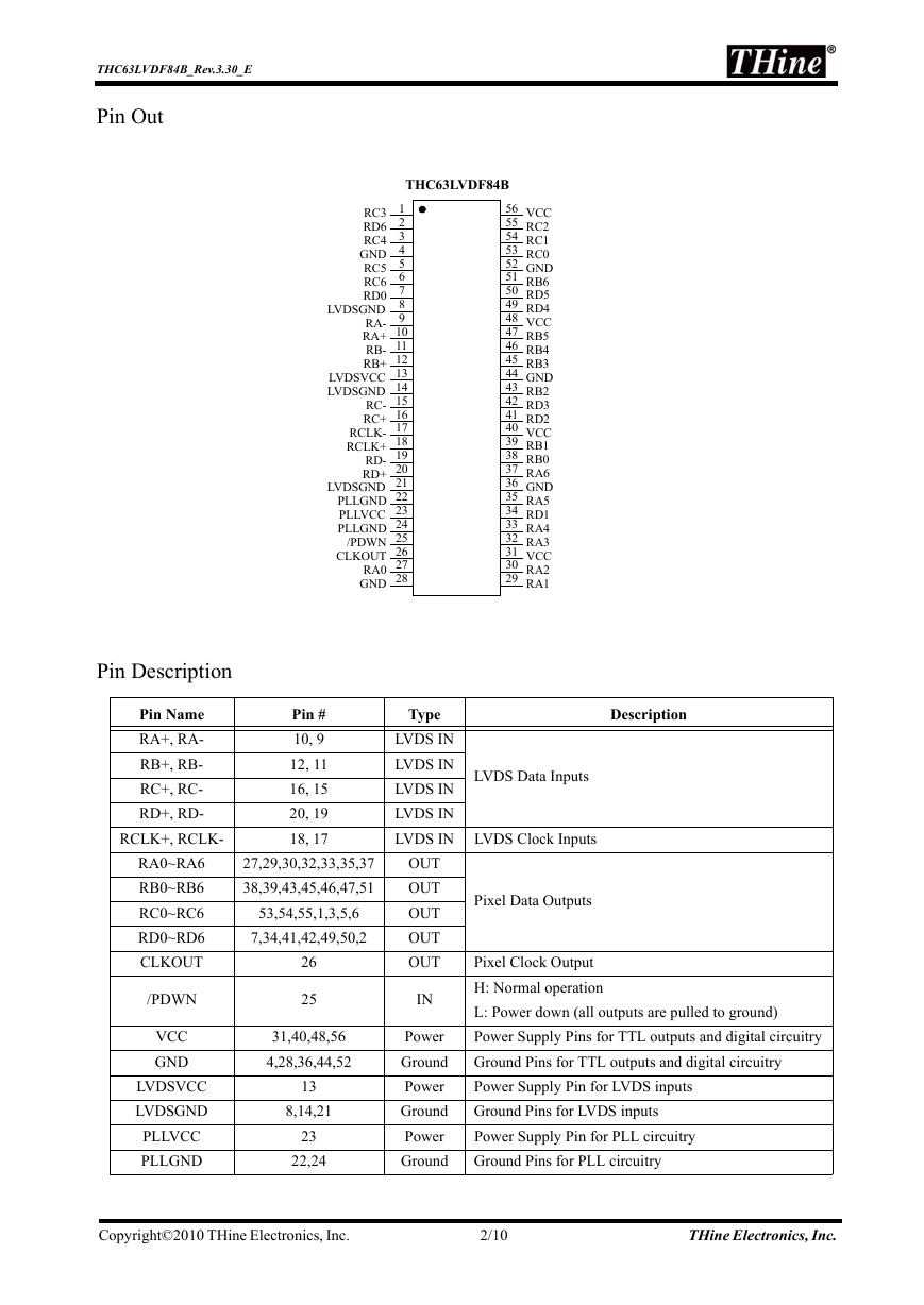
Pin Out
THC63LVDF84B
56
55
54
53
52
51
50
49
48
47
46
45
44
43
42
41
40
39
38
37
36
35
34
33
32
31
30
29
1
2
3
4
5
6
7
8
9
10
11
12
13
14
15
16
17
18
19
20
21
22
23
24
25
26
27
28
VCC
RC2
RC1
RC0
GND
RB6
RD5
RD4
VCC
RB5
RB4
RB3
GND
RB2
RD3
RD2
VCC
RB1
RB0
RA6
GND
RA5
RD1
RA4
RA3
VCC
RA2
RA1
RC3
RD6
RC4
GND
RC5
RC6
RD0
LVDSGND
RA-
RA+
RB-
RB+
LVDSVCC
LVDSGND
RC-
RC+
RCLK-
RCLK+
RD-
RD+
LVDSGND
PLLGND
PLLVCC
PLLGND
/PDWN
CLKOUT
RA0
GND
Pin Description
Pin Name
RA+, RA-
RB+, RB-
RC+, RC-
RD+, RD-
RCLK+, RCLK-
Pin #
10, 9
12, 11
16, 15
20, 19
18, 17
Type
Description
LVDS IN
LVDS IN
LVDS IN
LVDS IN
LVDS IN LVDS Clock Inputs
LVDS Data Inputs
RA0~RA6
RB0~RB6
RC0~RC6
RD0~RD6
CLKOUT
/PDWN
VCC
GND
LVDSVCC
LVDSGND
PLLVCC
PLLGND
27,29,30,32,33,35,37
38,39,43,45,46,47,51
53,54,55,1,3,5,6
7,34,41,42,49,50,2
26
25
31,40,48,56
4,28,36,44,52
13
8,14,21
23
22,24
OUT
OUT
OUT
OUT
OUT
IN
Power
Ground
Power
Ground
Power
Ground
Pixel Data Outputs
Pixel Clock Output
H: Normal operation
L: Power down (all outputs are pulled to ground)
Power Supply Pins for TTL outputs and digital circuitry
Ground Pins for TTL outputs and digital circuitry
Power Supply Pin for LVDS inputs
Ground Pins for LVDS inputs
Power Supply Pin for PLL circuitry
Ground Pins for PLL circuitry
Copyright©2010 THine Electronics, Inc. 2/10 THine Electronics, Inc.
�
THC63LVDF84B_Rev.3.30_E
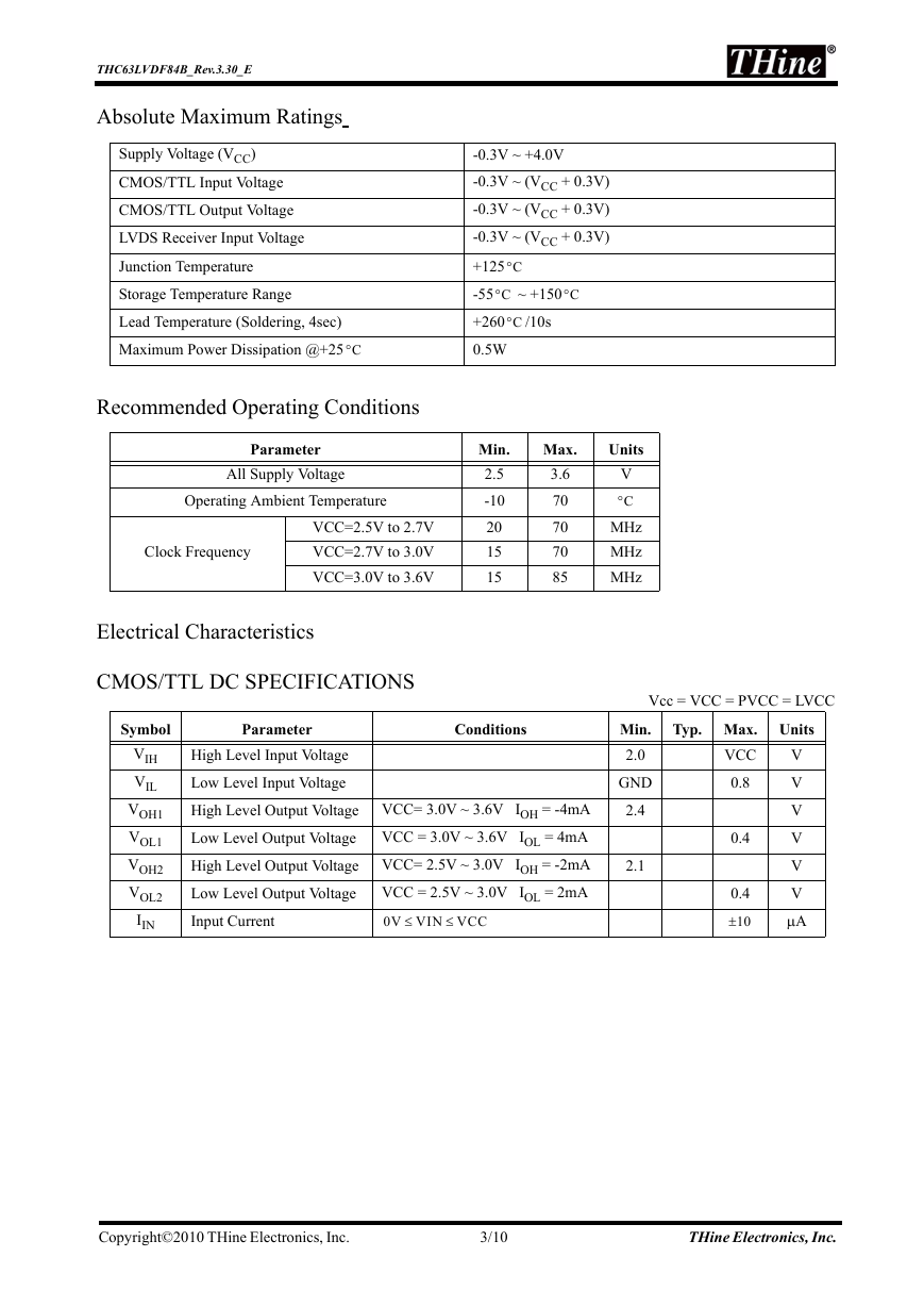
Absolute Maximum Ratings
Supply Voltage (VCC)
CMOS/TTL Input Voltage
CMOS/TTL Output Voltage
LVDS Receiver Input Voltage
Junction Temperature
Storage Temperature Range
Lead Temperature (Soldering, 4sec)
Maximum Power Dissipation @+25
°C
-0.3V ~ +4.0V
-0.3V ~ (VCC + 0.3V)
-0.3V ~ (VCC + 0.3V)
-0.3V ~ (VCC + 0.3V)
+125
-55
°C
+260
0.5W
°C
~ +150
°C
/10s
°C
Recommended Operating Conditions
Parameter
All Supply Voltage
Operating Ambient Temperature
Clock Frequency
VCC=2.5V to 2.7V
VCC=2.7V to 3.0V
VCC=3.0V to 3.6V
Min.
2.5
-10
20
15
15
Max.
3.6
70
70
70
85
Units
V
°C
MHz
MHz
MHz
Electrical Characteristics
CMOS/TTL DC SPECIFICATIONS
Symbol
Parameter
Conditions
VIH
VIL
VOH1
VOL1
VOH2
VOL2
IIN
High Level Input Voltage
Low Level Input Voltage
High Level Output Voltage
Low Level Output Voltage
High Level Output Voltage
Low Level Output Voltage
Input Current
VCC= 3.0V ~ 3.6V IOH = -4mA
VCC = 3.0V ~ 3.6V IOL = 4mA
VCC= 2.5V ~ 3.0V IOH = -2mA
VCC = 2.5V ~ 3.0V IOL = 2mA
0V VIN VCC
≤
≤
Vcc = VCC = PVCC = LVCC
Min.
2.0
GND
2.4
2.1
Typ. Max. Units
VCC
0.8
0.4
0.4
10±
V
V
V
V
V
V
μA
Copyright©2010 THine Electronics, Inc. 3/10 THine Electronics, Inc.
�
THC63LVDF84B_Rev.3.30_E
LVDS RECEIVER DC SPECIFICATIONS
Parameter
Conditions
Symbol
VTH
VTL
Differential Input High Threshold
Differential Input Low Threshold
IIN
Input Current
Supply Current
VIC = +1.2V
VIN = +2.4V/0V
VCC = 3.6V
Vcc = VCC = PVCC = LVCC
Typ.
Max.
100
Units
mV
mV
Min.
-100
10±
μA
Vcc = VCC = PVCC = LVCC
Typ. Max. Units
mA
mA
mA
41
52
30
53
64
42
Symbol
Parameter
Condition(*)
IRCCG
Receiver Supply Current
16Grayscale Pattern
CL=8pF, VCC=3.3V
CL=8pF, VCC=2.5V
f = 65MHz
f = 85MHz
f = 65MHz
16 Gray Scale Pattern
CLKIN
Rx0
Rx1
Rx2
Rx3
Rx4
Rx5
Rx6
Worst Case Pattern
CLKIN
EVEN RxIN
ODD RxIN
Copyright©2010 THine Electronics, Inc. 4/10 THine Electronics, Inc.
�
Typ. Max. Units
mA
mA
mA
72
84
42
94
96
64
10
μA
Vcc = VCC = PVCC = LVCC
Unit
Max.
50.0
66.6
66.6
THC63LVDF84B_Rev.3.30_E
Symbol
Parameter
Condition(*)
IRCCW
IRCCS
Receiver Supply Current
Worst Case Pattern
CL=8pF, VCC=3.3V
CL=8pF, VCC=2.5V
Receiver Power Down
Supply Current
/PDWN = L
f = 65MHz
f = 85MHz
f = 65MHz
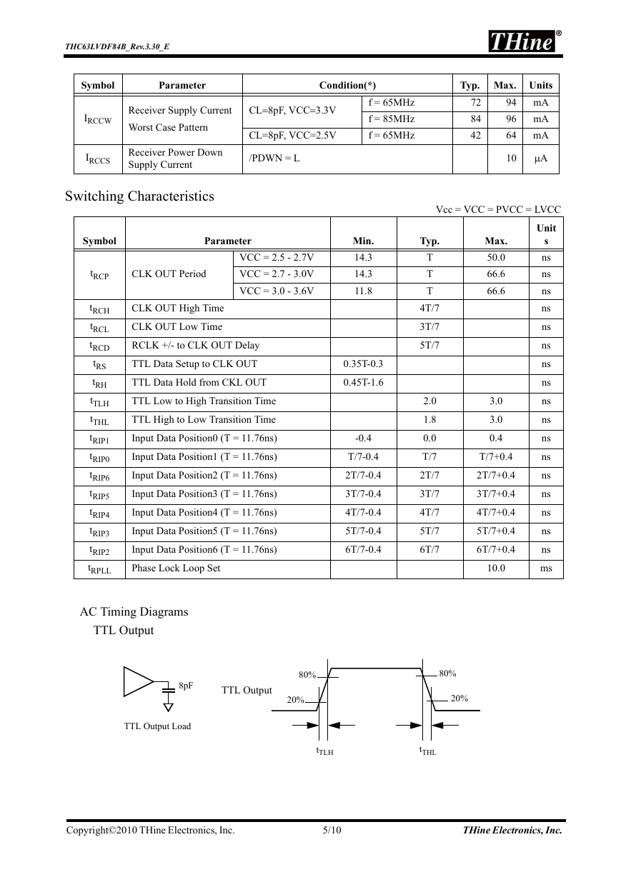
Switching Characteristics
Symbol
Parameter
CLK OUT Period
VCC = 2.5 - 2.7V
VCC = 2.7 - 3.0V
VCC = 3.0 - 3.6V
CLK OUT High Time
CLK OUT Low Time
RCLK +/- to CLK OUT Delay
TTL Data Setup to CLK OUT
TTL Data Hold from CKL OUT
TTL Low to High Transition Time
TTL High to Low Transition Time
Input Data Position0 (T = 11.76ns)
Input Data Position1 (T = 11.76ns)
Input Data Position2 (T = 11.76ns)
Input Data Position3 (T = 11.76ns)
Input Data Position4 (T = 11.76ns)
Input Data Position5 (T = 11.76ns)
Input Data Position6 (T = 11.76ns)
Phase Lock Loop Set
tRCP
tRCH
tRCL
tRCD
tRS
tRH
tTLH
tTHL
tRIP1
tRIP0
tRIP6
tRIP5
tRIP4
tRIP3
tRIP2
tRPLL
AC Timing Diagrams
TTL Output
Min.
14.3
14.3
11.8
0.35T-0.3
0.45T-1.6
-0.4
T/7-0.4
2T/7-0.4
3T/7-0.4
4T/7-0.4
5T/7-0.4
6T/7-0.4
Typ.
T
T
T
4T/7
3T/7
5T/7
s
ns
ns
ns
ns
ns
ns
ns
ns
ns
ns
ns
ns
ns
ns
ns
ns
ns
ms
2.0
1.8
0.0
T/7
2T/7
3T/7
4T/7
5T/7
6T/7
3.0
3.0
0.4
T/7+0.4
2T/7+0.4
3T/7+0.4
4T/7+0.4
5T/7+0.4
6T/7+0.4
10.0
8pF
TTL Output
80%
20%
80%
20%
TTL Output Load
tTLH
tTHL
Copyright©2010 THine Electronics, Inc. 5/10 THine Electronics, Inc.
�
THC63LVDF84B_Rev.3.30_E
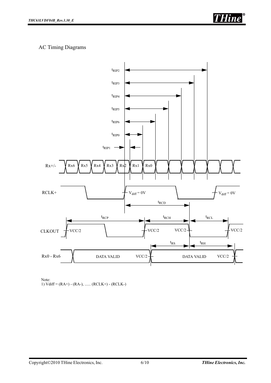
AC Timing Diagrams
tRIP2
tRIP3
tRIP4
tRIP5
tRIP6
tRIP0
tRIP1
Rx+/-
Rx6
Rx5
Rx4
Rx3
Rx2
Rx1
Rx0
RCLK+
Vdiff = 0V
Vdiff = 0V
tRCP
tRCD
tRCH
tRCL
CLKOUT
VCC/2
VCC/2
VCC/2
VCC/2
tRS
tRH
Rx0 - Rx6
DATA VALID
VCC/2
DATA VALID
VCC/2
Note:
1) Vdiff = (RA+) - (RA-), ...... (RCLK+) - (RCLK-)
Copyright©2010 THine Electronics, Inc. 6/10 THine Electronics, Inc.
�
THC63LVDF84B_Rev.3.30_E
AC Timing Diagrams
Phase Lock Loop Set Time
/PDWN
VCC/2
VCC
VCC/2
tRPLL
RCLK+/-
CLKOUT
3.6V
VCC/2
Copyright©2010 THine Electronics, Inc. 7/10 THine Electronics, Inc.
�
THC63LVDF84B_Rev.3.30_E
Note
1)Power On Sequence
Power on LVDS-Tx after THC63LVDF84B. If it is not avoidable, please contact to
mspsupport@thine.co.jp (for FAE mailing list)
2)Cable Connection and Disconnection
Don't connect and disconnect the LVDS cable, when the power is supplied to the system.
3)GND Connection
Connect the each GND of the PCB which LVDS-Tx and THC63LVDF84B on it. It is better for EMI reduction to
place GND cable as close to LVDS cable as possible.
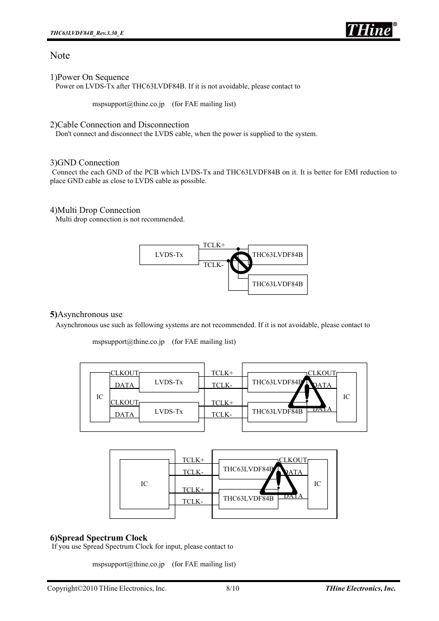
4)Multi Drop Connection
Multi drop connection is not recommended.
LVDS-Tx
TCLK+
TCLK-
THC63LVDF84B
THC63LVDF84B
5)Asynchronous use
Asynchronous use such as following systems are not recommended. If it is not avoidable, please contact to
mspsupport@thine.co.jp (for FAE mailing list)
CLKOUT
DATA
CLKOUT
DATA
IC
LVDS-Tx
LVDS-Tx
TCLK+
TCLK-
TCLK+
TCLK-
THC63LVDF84B
CLKOUT
DATA
THC63LVDF84B
DATA
IC
IC
TCLK+
TCLK-
TCLK+
TCLK-
THC63LVDF84B
CLKOUT
DATA
THC63LVDF84B
DATA
IC
6)Spread Spectrum Clock
If you use Spread Spectrum Clock for input, please contact to
mspsupport@thine.co.jp (for FAE mailing list)
Copyright©2010 THine Electronics, Inc. 8/10 THine Electronics, Inc.
�




 2023年江西萍乡中考道德与法治真题及答案.doc
 2012年重庆南川中考生物真题及答案.doc
 2013年江西师范大学地理学综合及文艺理论基础考研真题.doc
 2020年四川甘孜小升初语文真题及答案I卷.doc
 2020年注册岩土工程师专业基础考试真题及答案.doc
 2023-2024学年福建省厦门市九年级上学期数学月考试题及答案.doc
 2021-2022学年辽宁省沈阳市大东区九年级上学期语文期末试题及答案.doc
 2022-2023学年北京东城区初三第一学期物理期末试卷及答案.doc
 2018上半年江西教师资格初中地理学科知识与教学能力真题及答案.doc
 2012年河北国家公务员申论考试真题及答案-省级.doc
 2020-2021学年江苏省扬州市江都区邵樊片九年级上学期数学第一次质量检测试题及答案.doc
 2022下半年黑龙江教师资格证中学综合素质真题及答案.doc