logo资料库

MCNP6.2.pdf

第1页 / 共746页
第2页 / 共746页
第3页 / 共746页
第4页 / 共746页
第5页 / 共746页
第6页 / 共746页
第7页 / 共746页
第8页 / 共746页
资料共746页,剩余部分请下载后查看
mcnp6.2_Manual_cover.pdf
MCNP6_Users_Manual_Final-almost_compat_mode.pdf
1 MCNP INTRODUCTION AND PRIMER
1.1 Introduction
1.1.1 New MCNP6.2 Features and Capabilities
1.1.2 MCNP6 Versatility
1.1.3 User's Manual Organization
1.2 MCNP6 Primer:  Getting Started
1.3 MCNP6 Input for Sample Problem
1.3.1 INP File
1.3.2 Cell Cards
1.3.3 Surface Cards
1.3.4 Data Cards
1.3.4.1 MODE CARD
1.3.4.2 CELL AND SURFACE PARAMETER CARDS
1.3.4.3 SOURCE SPECIFICATION CARDS
1.3.4.4 TALLY SPECIFICATION CARDS
1.3.4.5 MATERIALS SPECIFICATION
1.3.4.6 PROBLEM TERMINATION
1.3.5 Sample Problem Input File
1.3.6 Running the Sample Problem
1.4 Executing MCNP6
1.4.1 Execution Line
1.4.2 Interrupts
Tips for Correct and Efficient Problems
1.5.1 Problem Setup
1.5.2 Preproduction
1.5.3 Production
1.5.4 Criticality
1.5.5 Warnings and Limitations
2 DESCRIPTION OF MCNP6 INPUT
2.1 Initiate-Run
2.2 Continue-Run
2.3 Card Format
2.4 Message Block
2.5 Problem Title Card
2.6 Comment Cards
2.7 Auxiliary Input File Capability
2.8 Cell, Surface, and Data Cards
2.8.1 Data Card Horizontal Input Format
2.8.2 Data Card Vertical Input Format
2.9 Particle Designators
2.10 Default Values
2.11 Input Error Messages
2.12 Geometry Errors
3 INPUT CARDS
3.1 Auxiliary Input File and Encryption (READ)
3.2 Geometry Specification
3.2.1 Cell Cards
3.2.2 Surface Cards
3.2.2.1 SURFACES DEFINED BY EQUATIONS
3.2.2.2 AXISYMMETRIC SURFACES DEFINED BY POINTS
3.2.2.3 GENERAL PLANE DEFINED BY THREE POINTS
3.2.2.4 SURFACES DEFINED BY MACROBODIES
3.2.2.4.1 BOX—Arbitrarily Oriented Orthogonal Box
3.2.2.4.2 RPP—Rectangular Parallelepiped
3.2.2.4.3 SPH—Sphere
3.2.2.4.4 RCC—Right Circular Cylinder
3.2.2.4.5 RHP or HEX—Right Hexagonal Prism
3.2.2.4.6 REC—Right Elliptical Cylinder
3.2.2.4.7 TRC—Truncated Right-Angle Cone
3.2.2.4.8 ELL—Ellipsoid
3.2.2.4.9 WED—Wedge
3.2.2.4.10 ARB—Arbitrary Polyhedron
3.2.2.4.11 Macrobody Facets
3.3 Data Cards
3.3.1 Data Cards Related to Geometry
3.3.1.1 VOL CELL VOLUME
3.3.1.2 AREA SURFACE AREA
3.3.1.3 TR COORDINATE TRANSFORMATION
3.3.1.4 TRCL CELL COORDINATE TRANSFORMATION
3.3.1.5 REPEATED STRUCTURES
3.3.1.5.1 U Universe
3.3.1.5.2 LAT Lattice
3.3.1.5.3 FILL Fill
3.3.1.5.4 URAN Stochastic Geometry for HTGRs
3.3.1.6 HYBRID GEOMETRIES: STRUCTURED AND UNSTRUCTURED MESHES
3.3.1.6.1 Creation of a Structured Discrete-Ordinates-Style Geometry File
3.3.1.6.2 Mesh Importation and Specification of an Embedded Geometry
3.3.2 Data Cards Related to Materials
3.3.2.1 M MATERIAL SPECIFICATION
3.3.2.2 MT S((,() THERMAL NEUTRON SCATTERING
3.3.2.3 MX MATERIAL CARD NUCLIDE SUBSTITUTION
3.3.2.4 MPN PHOTONUCLEAR NUCLIDE SELECTOR
3.3.2.5 OTFDB ON-THE-FLY-DOPPLER BROADENING
3.3.2.6 TOTNU TOTAL FISSION
3.3.2.7 NONU FISSION TURNOFF
3.3.2.8 AWTAB ATOMIC WEIGHT
3.3.2.9 XS CROSS-SECTION FILE
3.3.2.10 VOID MATERIAL VOID
3.3.2.11 MGOPT MULTIGROUP ADJOINT TRANSPORT OPTION
3.3.2.12 DRXS DISCRETE-REACTION CROSS SECTION
3.3.3 Data Cards Related to Physics
3.3.3.1 MODE PROBLEM TYPE
3.3.3.2 PHYS PARTICLE PHYSICS OPTIONS
3.3.3.2.1 Neutrons (PHYS:N)
3.3.3.2.2 Photons (PHYS:P)
3.3.3.2.3 Electrons (PHYS:E)
3.3.3.2.4 Protons (PHYS:H)
3.3.3.2.5 Other Particles (PHYS:)
3.3.3.3 ACT ACTIVATION CONTROL CARD
3.3.3.4 PHYSICS CUTOFFS
3.3.3.4.1 CUT: Time, Energy, and Weight Cutoffs
3.3.3.4.2 ELPT Cell-by-Cell Energy Cutoff
3.3.3.5 TMP FREE-GAS THERMAL TEMPERATURE
3.3.3.6 THTME THERMAL TIMES
3.3.3.7 MODEL PHYSICS
3.3.3.7.1 MPHYS Model Physics Control
3.3.3.7.2 LCA
3.3.3.7.3 LCB
3.3.3.7.4 LCC
3.3.3.7.5 LEA
3.3.3.7.6 LEB
3.3.3.8 FMULT MULTIPLICITY CONSTANTS
3.3.3.9 TRANSPORT OPTIONS (TROPT CARD)
3.3.3.10 UNCOLLIDED SECONDARIES (UNC CARD)
3.3.3.11 MAGNETIC FIELD TRACKING
3.3.3.11.1 Transfer Maps (COSYP and COSY Cards)
3.3.3.11.2 Particle Ray Tracing (BFLD and BFLCL Cards)
3.3.3.12 FIELD GRAVITATIONAL FIELD
3.3.4 Data Cards Related to Source Specification
3.3.4.1 SDEF GENERAL SOURCE DEFINITION
3.3.4.2 SI SOURCE INFORMATION
3.3.4.3 SP SOURCE PROBABILITY
3.3.4.4 SB SOURCE BIAS
3.3.4.5 DS DEPENDENT SOURCE DISTRIBUTION
3.3.4.6 SC SOURCE COMMENT
3.3.4.7 SSW SURFACE SOURCE WRITE
3.3.4.8 SSR SURFACE SOURCE READ
3.3.4.9 KCODE CRITICALITY SOURCE
3.3.4.10 KSRC CRITICALITY SOURCE POINTS
3.3.4.11 KOPTS CRITICALITY CALCULATIONS OPTIONS
3.3.4.12 HSRC MESH FOR SHANNON ENTROPY OF FISSION SOURCE DISTRIBUTION
3.3.4.13 BURN DEPLETION/BURNUP (KCODE PROBLEMS ONLY)
3.3.4.14 SUBROUTINES SOURCE AND SRCDX
3.3.5 Data Cards Related to Tally Specification
3.3.5.1 F STANDARD TALLIES
3.3.5.1.1 Surface and Cell Tallies (Tally Types 1, 2, 4, 6, and 7)
3.3.5.1.2 Detector Tallies (Tally Type 5)
3.3.5.1.3 Pulse-Height Tally (Tally Type 8)
3.3.5.1.4 Repeated Structures Tallies (Tally Types 1, 2, 4, 6, 7, and 8)
3.3.5.2 FC TALLY COMMENT
3.3.5.3 E TALLY ENERGY
3.3.5.4 T TALLY TIME
3.3.5.5 C TALLY COSINE (TALLY TYPE 1 AND 2)
3.3.5.6 FQ PRINT HIERARCHY
3.3.5.7 FM TALLY MULTIPLIER
3.3.5.8 DE AND DF DOSE ENERGY AND DOSE FUNCTION
3.3.5.9 EM ENERGY MULTIPLIER
3.3.5.10 TM TIME MULTIPLIER
3.3.5.11 CM COSINE MULTIPLIER (TALLY TYPES 1 AND 2 ONLY)
3.3.5.12 CF CELL FLAGGING (TALLY TYPES 1, 2, 4, 6, 7)
3.3.5.13 SF SURFACE FLAGGING (TALLY TYPES 1, 2, 4, 6, 7)
3.3.5.14 FS TALLY SEGMENT (TALLY TYPES 1, 2, 4, 6, 7)
3.3.5.15 SD SEGMENT DIVISOR (TALLY TYPES 1, 2, 4, 6, 7)
3.3.5.16 FU SPECIAL TALLY OR TALLYX INPUT
3.3.5.17 TALLYX USER-SUPPLIED SUBROUTINE
3.3.5.18 FT SPECIAL TREATMENTS FOR TALLIES
3.3.5.19 TF TALLY FLUCTUATION
3.3.5.20 NOTRN DIRECT-ONLY NEUTRAL-PARTICLE POINT DETECTOR CONTRIBUTIONS
3.3.5.21 PERT TALLY PERTURBATIONS—DIFFERENTIAL OPERATOR
3.3.5.22 KPERT REACTIVITY PERTURBATIONS—ADJOINT WEIGHTING
3.3.5.23 KSEN KEFF SENSITIVITY COEFFICIENTS—ADJOINT WEIGHTING
3.3.5.24 TMESH SUPERIMPOSED MESH TALLY A
3.3.5.24.1 Setting Up the TMESH Tally in the INP File
3.3.5.24.2 Track-Averaged TMESH Mesh Tally (Type 1)
3.3.5.24.3 Source TMESH Mesh Tally (Type 2)
3.3.5.24.4 Energy Deposition TMESH Mesh Tally (Type 3)
3.3.5.24.5 DXTRAN TMESH Mesh Tally (Type 4)
3.3.5.24.6 Processing the TMESH Mesh Tally Results
3.3.5.25 FMESH SUPERIMPOSED MESH TALLY B
3.3.5.26 SPDTL LATTICE SPEED TALLY ENHANCEMENT
3.3.6 Data Cards Related to Variance Reduction
3.3.6.1 IMP CELL IMPORTANCE
3.3.6.2 VAR VARIANCE REDUCTION CONTROL
3.3.6.3 WEIGHT-WINDOW CARDS
3.3.6.3.1 WWE Weight-Window Energies (or Times)
3.3.6.3.2 WWT Weight-Window Times
3.3.6.3.3 WWN Cell-Based Weight-Window Bounds
3.3.6.3.4 WWP Weight-Window Parameter
3.3.6.4 WEIGHT-WINDOW GENERATION CARDS
3.3.6.4.1 WWG Weight-Window Generation
3.3.6.4.2 WWGE Weight-Window Generation Energies (or Times)
3.3.6.4.3 WWGT Weight-Window Generation Times
3.3.6.4.4 MESH Superimposed Importance Mesh for Mesh-Based Weight-Window Generator
3.3.6.5 ESPLT ENERGY SPLITTING AND ROULETTE
3.3.6.6 TSPLT TIME SPLITTING AND ROULETTE
3.3.6.7 EXT EXPONENTIAL TRANSFORM
3.3.6.8 VECT VECTOR INPUT
3.3.6.9 FCL FORCED COLLISION
3.3.6.10 DXT DXTRAN SPHERE
3.3.6.11 DD DETECTOR DIAGNOSTICS
3.3.6.12 PD DETECTOR CONTRIBUTION
3.3.6.13 DXC DXTRAN CONTRIBUTION
3.3.6.14 BBREM BREMSSTRAHLUNG BIASING
3.3.6.15 PIKMT PHOTON-PRODUCTION BIASING
3.3.6.16 SPABI SECONDARY PARTICLE BIASING
3.3.6.17 PWT PHOTON WEIGHT
3.3.7 Problem Termination, Output Control, and Miscellaneous Data
3.3.7.1 PROBLEM TERMINATION
3.3.7.1.1 NPS History Cutoff
3.3.7.1.2 CTME Computer Time Cutoff
3.3.7.1.3 STOP Precision Cutoff
3.3.7.2 OUTPUT CONTROL
3.3.7.2.1 PRINT Output Print Tables
3.3.7.2.2 TALNP Negate Printing of Tallies
3.3.7.2.3 PRDMP Print and Dump Cycle
3.3.7.2.4 PTRAC Particle Track Output
3.3.7.2.5 MPLOT Plot Tally While Problem is Running
3.3.7.2.6 HISTP Create LAHET-Compatible files
3.3.7.3 MISCELLANEOUS DATA
3.3.7.3.1 RAND Random Number Generation
3.3.7.3.2 DBCN Debug Information
3.3.7.3.3 LOST Lost Particle Control
3.3.7.3.4 IDUM Integer Array
3.3.7.3.5 RDUM Floating-Point Array
3.3.7.3.6 ZA, ZB, ZC, and ZD Developers Card Placeholders
3.3.7.3.7 FILES File Creation
3.4 Summary of MCNP6 Input Cards
4 EXAMPLES
4.1 Geometry Examples
4.1.1 Geometry Specification
4.1.2 Coordinate Transformations
4.1.3 Repeated Structure and Lattice Examples
4.1.4 Embedded Meshes: Structured and Unstructured
4.2 Tally Examples
4.2.1 FM Examples (Simple Form)
4.2.2 FM Examples (General Form)
4.2.3 FMESH Tally Examples
4.2.4 FS Examples
4.2.5 FT Examples
4.2.6 Repeated Structure/Lattice Tally Example
4.2.7 Miscellaneous Tally Examples
4.2.7.1 LIGHT ION RECOIL (RECL)
4.2.7.2 INLINE GENERATION OF DOUBLE DIFFERENTIAL CROSS SECTIONS AND RESIDUAL NUCLEI
4.2.7.3 COMPTON IMAGE TALLY EXAMPLE
4.2.8 TALLYX Subroutine Examples
4.3 Source Examples
4.3.1 General Source
4.3.2 Beam Sources
4.3.3 Burning Multiple Materials In a Repeated Structure with Specified Concentration Changes
4.3.4 Source Subroutine
4.3.5 SRCDX Subroutine
4.4 Material Examples
4.4.1 Table Data/Model Physics Mix and Match
4.5 Physics Models
4.5.1 Neutron Production from a Spallation Target
5 MCNP GEOMETRY AND TALLY PLOTTING
5.1 System Graphics Information
5.2 The Geometry Plotter, PLOT
5.2.1 PLOT Input and Execute Line Options
5.2.2 Geometry Plotting Basic Concepts
5.2.3 Interactive Geometry Plotting in Point-and-Click Mode
5.2.4 Interactive Geometry Plotting in Command-Prompt Mode
5.2.5 Plotting Embedded-Mesh Geometries
5.2.6 Geometry Debugging
5.2.7 Geometry Plotting in Batch Mode
5.3 The Tally and Cross-Section Plotter, MCPLOT
5.3.1 Execution Line Options Related to MCPLOT Initiation
5.3.2 Plot Conventions and Command Syntax
5.3.2.1 2D PLOT
5.3.2.2 CONTOUR PLOT
5.3.2.3 COLOR-WASH PLOT
5.3.2.4 MCPLOT COMMAND SYNTAX
5.3.3 Tally Plot Commands Grouped by Function
5.3.4 MCTAL Files
5.4 Tally Plotting Examples
5.4.1 Example of Use of COPLOT
5.4.2 Tally Fluctuation Chart History Score Plotting
5.4.3 Radiography Tally Contour Plot Example
5.4.4 TMESH Mesh Tally Plot Examples
5.4.4.1 MCPLOT TMESH MESH TALLY
5.4.4.2 SUPERIMPOSED GEOMETRY PLOT TMESH MESH TALLY
5.4.5 MCPLOT FREE Command Examples
5.4.6 Photonuclear Cross-Section Plots
5.4.7 Lattice Tally Plot Example
5.4.8 Weight-Window-Generator Superimposed Mesh Plots
5.4.8.1 CYLINDRICAL MESH EXAMPLE
5.4.8.2 SPHERICAL MESH EXAMPLE
5.5 Normalization of Energy-Dependent Tally Plots
5.5.1 MCNP6 Tally Values and Energy-Normalized Tallies
5.5.2 Definition of Neutron Lethargy
5.5.3 Lethargy-Normalized Tallies for a Logarithmic Energy Abscissa
5.5.4 Relation of Tally Lethargy Normalizing to Tally Energy Normalizing
5.5.5 Average Energy for a Lethargy-Normalized Tally
5.5.6 MCNP6 LETHARGY Command for Lethargy Normalization
5.5.7 Requirements for Producing a Visually Accurate Area (VAA) Tally Plot
5.5.8 Comparisons of Energy and Lethargy Tally Normalizations for a Log Energy Abscissa
5.5.9 Summary of Energy-Normalized and Lethargy-Normalized MCNP6 Tally Plots
6 REFERENCES
7 APPENDIX A—A SUMMARY OF MCNP6 COMMANDS
7.1 General Information, File Names, Execution Line, Units
7.1.1 Form of Input (INP) File: Required to Initiate & Run a Problem
7.1.2 Form of CONTINUE Input File:  Requires a RUNPTE File
7.1.3 MCNP6 File Names and Contents
7.1.4 MCNP6 Execution Line Options and Useful Combinations
7.1.5 Execution Lines for Various Type of Problems
7.1.6 MCNP6 Physical Units and Tally Units
7.1.7 MCNP6 Interrupts
7.1.8 Example of an MCNP6 Fixed-Source INP File
7.1.9 Example of a keff Eigenvalue INP File
7.2 Input (INP) File Commands
7.2.1 Input Command Formats
7.2.1.1 HORIZONTAL 128-CHARACTER INPUT FORMAT
7.2.1.2 VERTICAL (COLUMN) INPUT FORMAT FOR CELL PARAMETERS AND SOURCE DISTRIBUTIONS
7.2.1.3 PARTICLE DESIGNATORS
7.2.2 Input Commands (Alphabetical)
7.2.3 Input Commands (by Function)
7.2.4 Concise Input Command Descriptions
7.3 Geometry Plotting Commands
7.3.1 Geometry Plotting Command Formats
7.3.2 Geometry Plotting Commands (Alphabetical)
7.3.3 Geometry Plotting Commands (by Function)
7.3.4 Concise Geometry Plotting Command Descriptions
7.4 Tally and Cross-Section Plotting Commands
7.4.1 Tally and Cross-Section Plotting Command Formats
7.4.2 Tally and Cross-Sections Plotting Commands (Alphabetical)
7.4.3 Tally and Cross-Section Plotting Commands (by Function)
7.4.4 Concise Tally and Cross-Section Plotting Command Description
8 APPENDIX B MESH-BASED WWINP, WWOUT, AND WWONE FILE FORMAT
9 APPENDIX C FISSION SPECTRA CONSTANTS
9.1 Constants for Fission Spectra
9.1.1 Constants for the Maxwell Fission Spectrum (neutron-induced)
9.1.2 Constants for the Watt Fission Spectrum
9.1.2.1 NEUTRON-INDUCED FISSION
9.1.2.2 SPONTANEOUS FISSION
10 APPENDIX D PTRAC TABLES
11 APPENDIX E XSDIR DATA DIRECTORY FILE
12 APPENDIX F SUPPLEMENTAL PHYSICS INFORMATION
MCNP User’s Manual Code Version 6.2
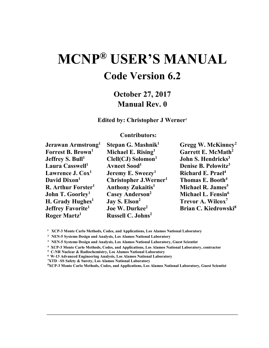
MCNP® USER’S MANUAL Code Version 6.2 October 27, 2017 Manual Rev. 0 Edited by: Christopher J Werner1 Jerawan Armstrong1 Forrest B. Brown1 Jeffrey S. Bull1 Laura Casswell1 Lawrence J. Cox1 David Dixon1 R. Arthur Forster1 John T. Goorley1 H. Grady Hughes1 Jeffrey Favorite1 Roger Martz1 Contributors: Stepan G. Mashnik1 Michael E. Rising1 Clell(CJ) Solomon1 Avneet Sood1 Jeremy E. Sweezy1 Christopher J.Werner1 Anthony Zukaitis1 Casey Anderson2 Jay S. Elson2 Joe W. Durkee2 Russell C. Johns2 Gregg W. McKinney2 Garrett E. McMath2 John S. Hendricks3 Denise B. Pelowitz3 Richard E. Prael4 Thomas E. Booth4 Michael R. James5 Michael L. Fensin6 Trevor A. Wilcox7 Brian C. Kiedrowski8 1 XCP-3 Monte Carlo Methods, Codes, and Applications, Los Alamos National Laboratory 2 NEN-5 Systems Design and Analysis, Los Alamos National Laboratory 3 NEN-5 Systems Design and Analysis, Los Alamos National Laboratory, Guest Scientist 4 XCP-3 Monte Carlo Methods, Codes, and Applications, Los Alamos National Laboratory, contractor 5 C-NR Nuclear & Radiochemistry, Los Alamos National Laboratory 6 W-13 Advanced Engineering Analysis, Los Alamos National Laboratory 7XTD –SS Safety & Surety, Los Alamos National Laboratory 8XCP-3 Monte Carlo Methods, Codes, and Applications, Los Alamos National Laboratory, Guest Scientist
MCNP User’s Manual TABLE OF CONTENTS Copyright Notice & Disclaimer © Copyright (2018). Los Alamos National Security, LLC. All rights reserved. This material was produced under U.S. Government contract DE-AC52-06NA25396 for Los Alamos National Laboratory, which is operated by Los Alamos National Security, LLC for the U.S. Department of Energy. The Government is granted for itself and others acting on its behalf a paid-up, nonexclusive, irrevocable worldwide license in this material to reproduce, prepare derivative works, and perform publicly and display publicly. Beginning five (5) years after February 14, 2018, subject to additional five-year worldwide renewals, the Government is granted for itself and others acting on its behalf a paid-up, nonexclusive, irrevocable worldwide license in this material to reproduce, prepare derivative works, distribute copies to the public, perform publicly and display publicly, and to permit others to do so. NEITHER THE UNITED STATES NOR THE UNITED STATES DEPARTMENT OF ENERGY, NOR LOS ALAMOS NATIONAL SECURITY, LLC, NOR ANY OF THEIR EMPLOYEES, MAKES ANY WARRANTY, EXPRESS OR IMPLIED, OR ASSUMES ANY LEGAL LIABILITY OR RESPONSIBILITY FOR THE ACCURACY, COMPLETENESS, OR USEFULNESS OF ANY INFORMATION, APPARATUS, PRODUCT, OR PROCESS DISCLOSED, OR REPRESENTS THAT ITS USE WOULD NOT INFRINGE PRIVATELY OWNED RIGHTS. MCNP® and Monte Carlo N-Particle® are registered trademarks owned by Los Alamos National Security, LLC, manager and operator of Los Alamos National Laboratory. Any third party use of such registered marks should be properly attributed to Los Alamos National Security, LLC, including the use of the ® designation as appropriate. Any questions regarding licensing, proper use, and/or proper attribution of Los Alamos National Security, LLC marks should be directed to trademarks@lanl.gov. MCNP6, MCNPX, MCNP5, MCNP Version 5, LAHET, and LAHET Code System (LCS) are trademarks of Los Alamos National Security, LLC. MCNP User’s Manual iii
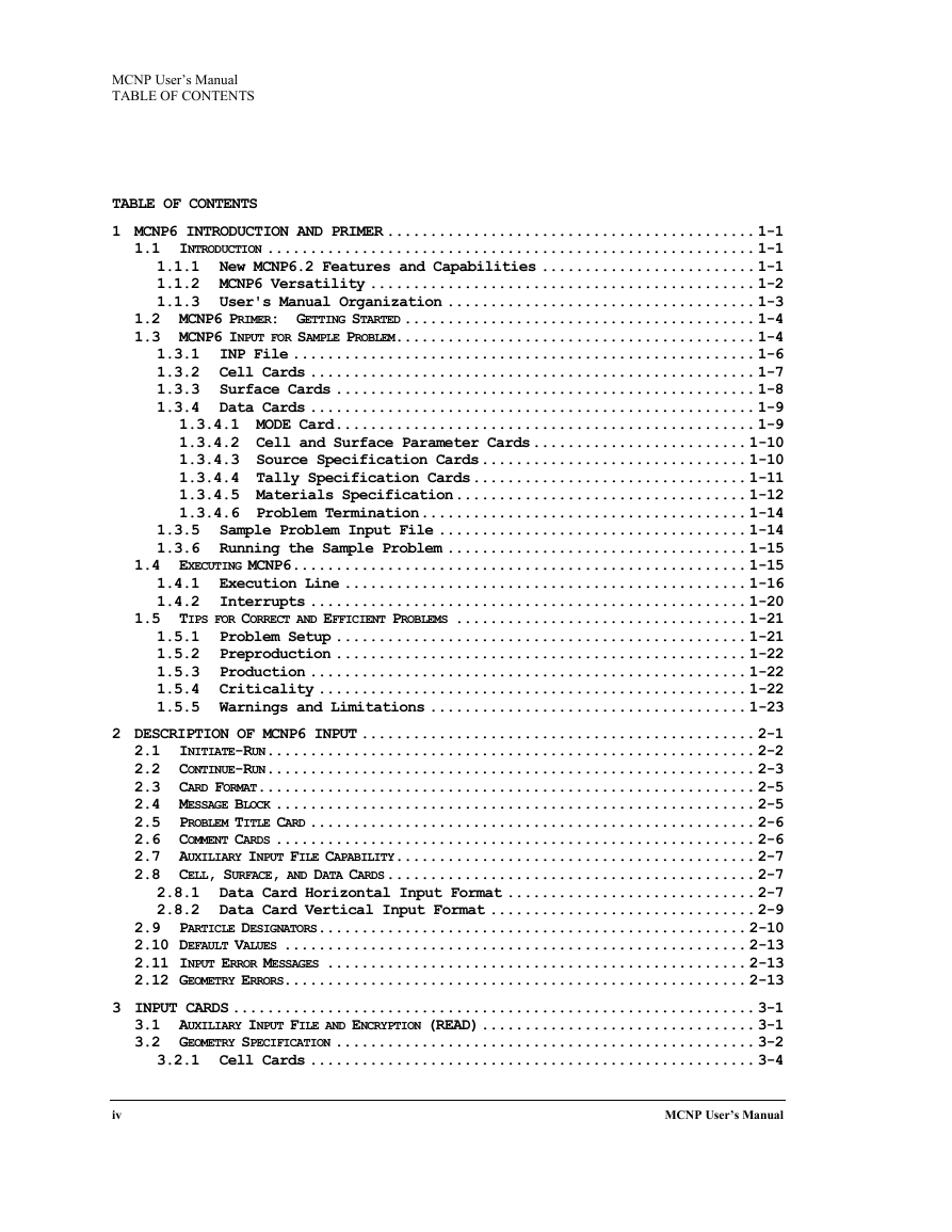
MCNP User’s Manual TABLE OF CONTENTS TABLE OF CONTENTS 1 MCNP6 INTRODUCTION AND PRIMER ........................................... 1-1 1.1 INTRODUCTION ......................................................... 1-1 1.1.1 New MCNP6.2 Features and Capabilities ......................... 1-1 1.1.2 MCNP6 Versatility ............................................. 1-2 1.1.3 User's Manual Organization .................................... 1-3 1.2 MCNP6 PRIMER: GETTING STARTED ......................................... 1-4 1.3 MCNP6 INPUT FOR SAMPLE PROBLEM .......................................... 1-4 1.3.1 INP File ...................................................... 1-6 1.3.2 Cell Cards .................................................... 1-7 1.3.3 Surface Cards ................................................. 1-8 1.3.4 Data Cards .................................................... 1-9 1.3.4.1 MODE Card ................................................. 1-9 1.3.4.2 Cell and Surface Parameter Cards ......................... 1-10 1.3.4.3 Source Specification Cards ............................... 1-10 1.3.4.4 Tally Specification Cards ................................ 1-11 1.3.4.5 Materials Specification .................................. 1-12 1.3.4.6 Problem Termination ...................................... 1-14 1.3.5 Sample Problem Input File .................................... 1-14 1.3.6 Running the Sample Problem ................................... 1-15 1.4 EXECUTING MCNP6 ..................................................... 1-15 1.4.1 Execution Line ............................................... 1-16 1.4.2 Interrupts ................................................... 1-20 1.5 TIPS FOR CORRECT AND EFFICIENT PROBLEMS .................................. 1-21 1.5.1 Problem Setup ................................................ 1-21 1.5.2 Preproduction ................................................ 1-22 1.5.3 Production ................................................... 1-22 1.5.4 Criticality .................................................. 1-22 1.5.5 Warnings and Limitations ..................................... 1-23 2 DESCRIPTION OF MCNP6 INPUT .............................................. 2-1 2.1 INITIATE-RUN ......................................................... 2-2 2.2 CONTINUE-RUN ......................................................... 2-3 2.3 CARD FORMAT .......................................................... 2-5 2.4 MESSAGE BLOCK ........................................................ 2-5 2.5 PROBLEM TITLE CARD .................................................... 2-6 2.6 COMMENT CARDS ........................................................ 2-6 2.7 AUXILIARY INPUT FILE CAPABILITY .......................................... 2-7 2.8 CELL, SURFACE, AND DATA CARDS ........................................... 2-7 2.8.1 Data Card Horizontal Input Format ............................. 2-7 2.8.2 Data Card Vertical Input Format ............................... 2-9 2.9 PARTICLE DESIGNATORS .................................................. 2-10 2.10 DEFAULT VALUES ...................................................... 2-13 2.11 INPUT ERROR MESSAGES ................................................. 2-13 2.12 GEOMETRY ERRORS...................................................... 2-13 3 INPUT CARDS ............................................................. 3-1 3.1 AUXILIARY INPUT FILE AND ENCRYPTION (READ) ................................ 3-1 3.2 GEOMETRY SPECIFICATION ................................................. 3-2 3.2.1 Cell Cards .................................................... 3-4 iv MCNP User’s Manual
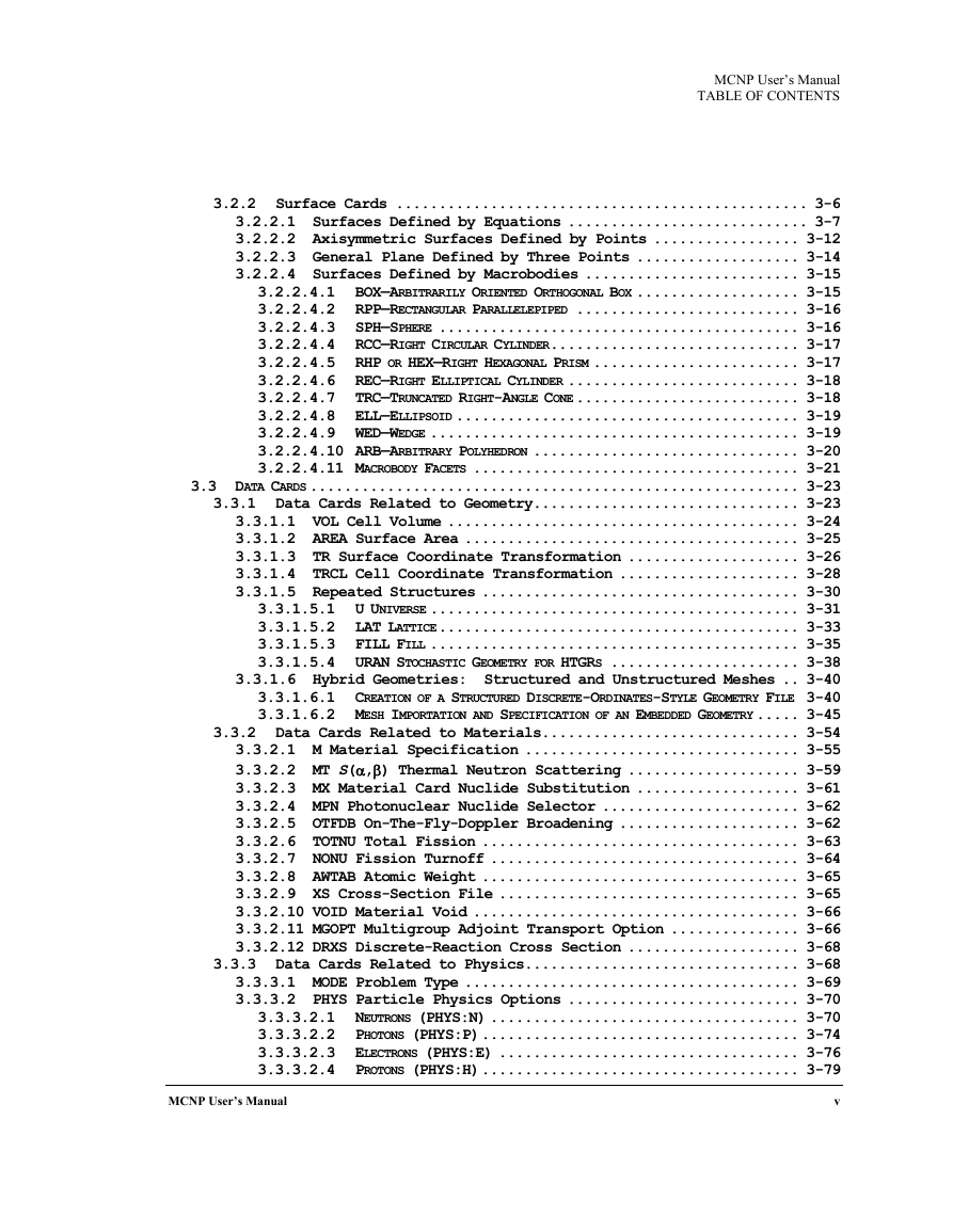
MCNP User’s Manual TABLE OF CONTENTS 3.2.2 Surface Cards ................................................ 3-6 3.2.2.1 Surfaces Defined by Equations ............................ 3-7 3.2.2.2 Axisymmetric Surfaces Defined by Points ................. 3-12 3.2.2.3 General Plane Defined by Three Points ................... 3-14 3.2.2.4 Surfaces Defined by Macrobodies ......................... 3-15 3.2.2.4.1 BOX—ARBITRARILY ORIENTED ORTHOGONAL BOX ................... 3-15 3.2.2.4.2 RPP—RECTANGULAR PARALLELEPIPED .......................... 3-16 3.2.2.4.3 SPH—SPHERE .......................................... 3-16 3.2.2.4.4 RCC—RIGHT CIRCULAR CYLINDER ............................. 3-17 3.2.2.4.5 RHP OR HEX—RIGHT HEXAGONAL PRISM ........................ 3-17 3.2.2.4.6 REC—RIGHT ELLIPTICAL CYLINDER ........................... 3-18 3.2.2.4.7 TRC—TRUNCATED RIGHT-ANGLE CONE .......................... 3-18 3.2.2.4.8 ELL—ELLIPSOID ........................................ 3-19 3.2.2.4.9 WED—WEDGE ........................................... 3-19 3.2.2.4.10 ARB—ARBITRARY POLYHEDRON ............................... 3-20 3.2.2.4.11 MACROBODY FACETS ...................................... 3-21 3.3 DATA CARDS ......................................................... 3-23 3.3.1 Data Cards Related to Geometry............................... 3-23 3.3.1.1 VOL Cell Volume ......................................... 3-24 3.3.1.2 AREA Surface Area ....................................... 3-25 3.3.1.3 TR Surface Coordinate Transformation .................... 3-26 3.3.1.4 TRCL Cell Coordinate Transformation ..................... 3-28 3.3.1.5 Repeated Structures ..................................... 3-30 3.3.1.5.1 U UNIVERSE ........................................... 3-31 3.3.1.5.2 LAT LATTICE .......................................... 3-33 3.3.1.5.3 FILL FILL ........................................... 3-35 3.3.1.5.4 URAN STOCHASTIC GEOMETRY FOR HTGRS ...................... 3-38 3.3.1.6 Hybrid Geometries: Structured and Unstructured Meshes .. 3-40 3.3.1.6.1 CREATION OF A STRUCTURED DISCRETE-ORDINATES-STYLE GEOMETRY FILE 3-40 3.3.1.6.2 MESH IMPORTATION AND SPECIFICATION OF AN EMBEDDED GEOMETRY ..... 3-45 3.3.2 Data Cards Related to Materials.............................. 3-54 3.3.2.1 M Material Specification ................................ 3-55 3.3.2.2 MT S(α,β) Thermal Neutron Scattering .................... 3-59 3.3.2.3 MX Material Card Nuclide Substitution ................... 3-61 3.3.2.4 MPN Photonuclear Nuclide Selector ....................... 3-62 3.3.2.5 OTFDB On-The-Fly-Doppler Broadening ..................... 3-62 3.3.2.6 TOTNU Total Fission ..................................... 3-63 3.3.2.7 NONU Fission Turnoff .................................... 3-64 3.3.2.8 AWTAB Atomic Weight ..................................... 3-65 3.3.2.9 XS Cross-Section File ................................... 3-65 3.3.2.10 VOID Material Void ...................................... 3-66 3.3.2.11 MGOPT Multigroup Adjoint Transport Option ............... 3-66 3.3.2.12 DRXS Discrete-Reaction Cross Section .................... 3-68 3.3.3 Data Cards Related to Physics................................ 3-68 3.3.3.1 MODE Problem Type ....................................... 3-69 3.3.3.2 PHYS Particle Physics Options ........................... 3-70 3.3.3.2.1 NEUTRONS (PHYS:N) .................................... 3-70 3.3.3.2.2 PHOTONS (PHYS:P) ..................................... 3-74 3.3.3.2.3 ELECTRONS (PHYS:E) ................................... 3-76 3.3.3.2.4 PROTONS (PHYS:H) ..................................... 3-79 v MCNP User’s Manual
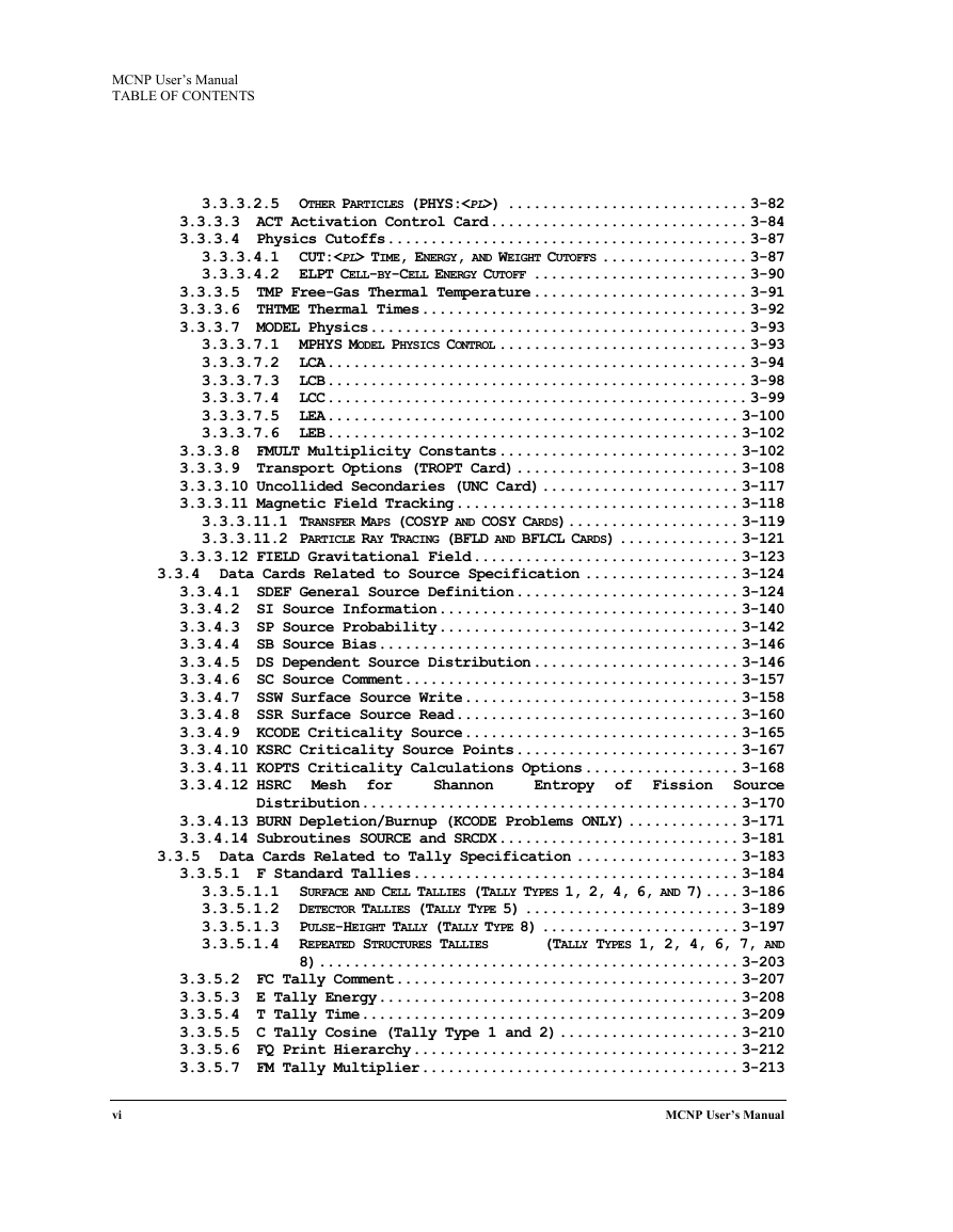
MCNP User’s Manual TABLE OF CONTENTS 3.3.3.2.5 OTHER PARTICLES (PHYS:) ............................ 3-82 3.3.3.3 ACT Activation Control Card .............................. 3-84 3.3.3.4 Physics Cutoffs .......................................... 3-87 3.3.3.4.1 CUT: TIME, ENERGY, AND WEIGHT CUTOFFS ................. 3-87 3.3.3.4.2 ELPT CELL-BY-CELL ENERGY CUTOFF ......................... 3-90 3.3.3.5 TMP Free-Gas Thermal Temperature ......................... 3-91 3.3.3.6 THTME Thermal Times ...................................... 3-92 3.3.3.7 MODEL Physics ............................................ 3-93 3.3.3.7.1 MPHYS MODEL PHYSICS CONTROL ............................. 3-93 3.3.3.7.2 LCA ................................................. 3-94 3.3.3.7.3 LCB ................................................. 3-98 3.3.3.7.4 LCC ................................................. 3-99 3.3.3.7.5 LEA ................................................ 3-100 3.3.3.7.6 LEB ................................................ 3-102 3.3.3.8 FMULT Multiplicity Constants ............................ 3-102 3.3.3.9 Transport Options (TROPT Card) .......................... 3-108 3.3.3.10 Uncollided Secondaries (UNC Card) ....................... 3-117 3.3.3.11 Magnetic Field Tracking ................................. 3-118 3.3.3.11.1 TRANSFER MAPS (COSYP AND COSY CARDS) .................... 3-119 3.3.3.11.2 PARTICLE RAY TRACING (BFLD AND BFLCL CARDS) .............. 3-121 3.3.3.12 FIELD Gravitational Field ............................... 3-123 3.3.4 Data Cards Related to Source Specification .................. 3-124 3.3.4.1 SDEF General Source Definition .......................... 3-124 3.3.4.2 SI Source Information ................................... 3-140 3.3.4.3 SP Source Probability ................................... 3-142 3.3.4.4 SB Source Bias .......................................... 3-146 3.3.4.5 DS Dependent Source Distribution ........................ 3-146 3.3.4.6 SC Source Comment ....................................... 3-157 3.3.4.7 SSW Surface Source Write ................................ 3-158 3.3.4.8 SSR Surface Source Read ................................. 3-160 3.3.4.9 KCODE Criticality Source ................................ 3-165 3.3.4.10 KSRC Criticality Source Points .......................... 3-167 3.3.4.11 KOPTS Criticality Calculations Options .................. 3-168 3.3.4.12 HSRC Mesh for Shannon Entropy of Fission Source Distribution ............................................ 3-170 3.3.4.13 BURN Depletion/Burnup (KCODE Problems ONLY) ............. 3-171 3.3.4.14 Subroutines SOURCE and SRCDX ............................ 3-181 3.3.5 Data Cards Related to Tally Specification ................... 3-183 3.3.5.1 F Standard Tallies ...................................... 3-184 3.3.5.1.1 SURFACE AND CELL TALLIES (TALLY TYPES 1, 2, 4, 6, AND 7) .... 3-186 3.3.5.1.2 DETECTOR TALLIES (TALLY TYPE 5) ......................... 3-189 3.3.5.1.3 PULSE-HEIGHT TALLY (TALLY TYPE 8) ....................... 3-197 3.3.5.1.4 REPEATED STRUCTURES TALLIES (TALLY TYPES 1, 2, 4, 6, 7, AND 8) ................................................. 3-203 3.3.5.2 FC Tally Comment ........................................ 3-207 3.3.5.3 E Tally Energy .......................................... 3-208 3.3.5.4 T Tally Time ............................................ 3-209 3.3.5.5 C Tally Cosine (Tally Type 1 and 2) ..................... 3-210 3.3.5.6 FQ Print Hierarchy ...................................... 3-212 3.3.5.7 FM Tally Multiplier ..................................... 3-213 vi MCNP User’s Manual
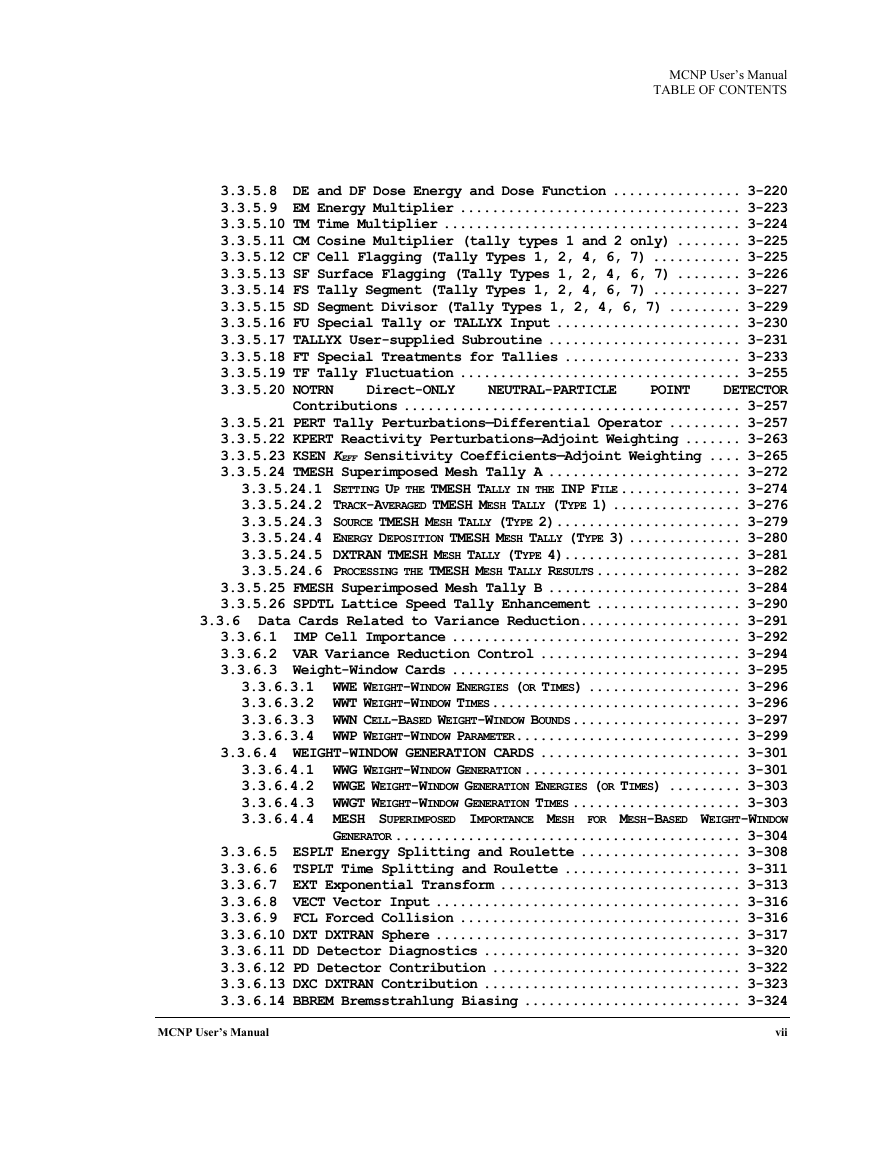
MCNP User’s Manual TABLE OF CONTENTS Direct-ONLY POINT NEUTRAL-PARTICLE 3.3.5.8 DE and DF Dose Energy and Dose Function ................ 3-220 3.3.5.9 EM Energy Multiplier ................................... 3-223 3.3.5.10 TM Time Multiplier ..................................... 3-224 3.3.5.11 CM Cosine Multiplier (tally types 1 and 2 only) ........ 3-225 3.3.5.12 CF Cell Flagging (Tally Types 1, 2, 4, 6, 7) ........... 3-225 3.3.5.13 SF Surface Flagging (Tally Types 1, 2, 4, 6, 7) ........ 3-226 3.3.5.14 FS Tally Segment (Tally Types 1, 2, 4, 6, 7) ........... 3-227 3.3.5.15 SD Segment Divisor (Tally Types 1, 2, 4, 6, 7) ......... 3-229 3.3.5.16 FU Special Tally or TALLYX Input ....................... 3-230 3.3.5.17 TALLYX User-supplied Subroutine ........................ 3-231 3.3.5.18 FT Special Treatments for Tallies ...................... 3-233 3.3.5.19 TF Tally Fluctuation ................................... 3-255 3.3.5.20 NOTRN DETECTOR Contributions .......................................... 3-257 3.3.5.21 PERT Tally Perturbations—Differential Operator ......... 3-257 3.3.5.22 KPERT Reactivity Perturbations—Adjoint Weighting ....... 3-263 3.3.5.23 KSEN KEFF Sensitivity Coefficients—Adjoint Weighting .... 3-265 3.3.5.24 TMESH Superimposed Mesh Tally A ........................ 3-272 3.3.5.24.1 SETTING UP THE TMESH TALLY IN THE INP FILE ............... 3-274 3.3.5.24.2 TRACK-AVERAGED TMESH MESH TALLY (TYPE 1) ................ 3-276 3.3.5.24.3 SOURCE TMESH MESH TALLY (TYPE 2) ....................... 3-279 3.3.5.24.4 ENERGY DEPOSITION TMESH MESH TALLY (TYPE 3) .............. 3-280 3.3.5.24.5 DXTRAN TMESH MESH TALLY (TYPE 4) ...................... 3-281 3.3.5.24.6 PROCESSING THE TMESH MESH TALLY RESULTS .................. 3-282 3.3.5.25 FMESH Superimposed Mesh Tally B ........................ 3-284 3.3.5.26 SPDTL Lattice Speed Tally Enhancement .................. 3-290 3.3.6 Data Cards Related to Variance Reduction .................... 3-291 3.3.6.1 IMP Cell Importance .................................... 3-292 3.3.6.2 VAR Variance Reduction Control ......................... 3-294 3.3.6.3 Weight-Window Cards .................................... 3-295 3.3.6.3.1 WWE WEIGHT-WINDOW ENERGIES (OR TIMES) ................... 3-296 3.3.6.3.2 WWT WEIGHT-WINDOW TIMES ............................... 3-296 3.3.6.3.3 WWN CELL-BASED WEIGHT-WINDOW BOUNDS ..................... 3-297 3.3.6.3.4 WWP WEIGHT-WINDOW PARAMETER ............................ 3-299 3.3.6.4 WEIGHT-WINDOW GENERATION CARDS ......................... 3-301 3.3.6.4.1 WWG WEIGHT-WINDOW GENERATION ........................... 3-301 3.3.6.4.2 WWGE WEIGHT-WINDOW GENERATION ENERGIES (OR TIMES) ......... 3-303 3.3.6.4.3 WWGT WEIGHT-WINDOW GENERATION TIMES ..................... 3-303 3.3.6.4.4 MESH SUPERIMPOSED IMPORTANCE MESH FOR MESH-BASED WEIGHT-WINDOW GENERATOR ........................................... 3-304 3.3.6.5 ESPLT Energy Splitting and Roulette .................... 3-308 3.3.6.6 TSPLT Time Splitting and Roulette ...................... 3-311 3.3.6.7 EXT Exponential Transform .............................. 3-313 3.3.6.8 VECT Vector Input ...................................... 3-316 3.3.6.9 FCL Forced Collision ................................... 3-316 3.3.6.10 DXT DXTRAN Sphere ...................................... 3-317 3.3.6.11 DD Detector Diagnostics ................................ 3-320 3.3.6.12 PD Detector Contribution ............................... 3-322 3.3.6.13 DXC DXTRAN Contribution ................................ 3-323 3.3.6.14 BBREM Bremsstrahlung Biasing ........................... 3-324 vii MCNP User’s Manual
分享到:
收藏