Qualcomm Atheros, Inc.
IPQ4018/IPQ4028/IPQ4019/IPQ4029 RF Test
User Guide
80-Y9700-3 Rev. J
July 28, 2016
Confidential and Proprietary – Qualcomm Atheros, Inc.
NO PUBLIC DISCLOSURE PERMITTED: Please report postings of this document on public servers or websites to:
DocCtrlAgent@qualcomm.com.
Restricted Distribution: Not to be distributed to anyone who is not an employee of either Qualcomm Atheros, Inc. or its affiliated companies
without the express approval of Qualcomm Configuration Management.
Not to be used, copied, reproduced, or modified in whole or in part, nor its contents revealed in any manner to others without the express
written permission of Qualcomm Atheros, Inc.
Qualcomm is a trademark of Qualcomm Incorporated, registered in the United States and other countries. Other product and brand names
may be trademarks or registered trademarks of their respective owners.
This technical data may be subject to U.S. and international export, re-export, or transfer (“export”) laws. Diversion contrary to U.S. and
international law is strictly prohibited.
Qualcomm Atheros, Inc.
1700 Technology Drive
San Jose, CA 95110
U.S.A.
© 2015 - 2016 Qualcomm Atheros, Inc. All rights reserved.
�
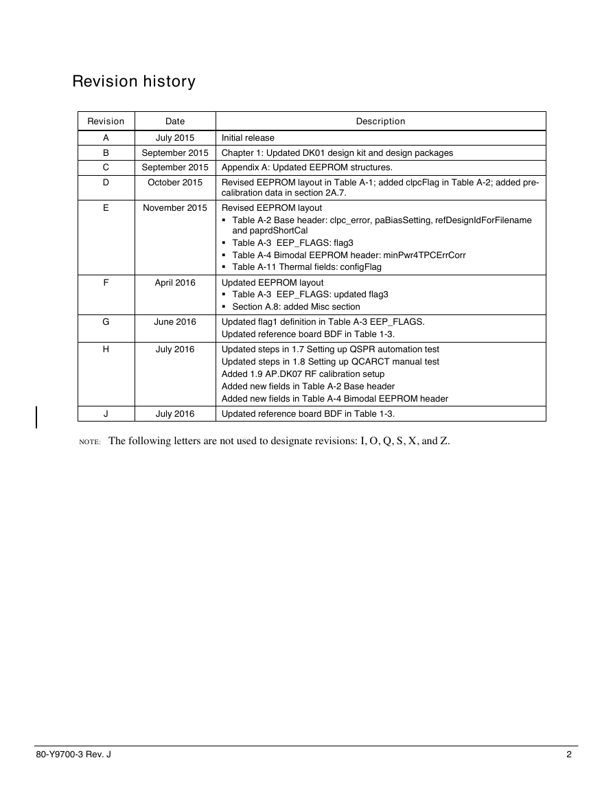
Revision history
Revision
Date
Description
A
B
C
D
E
F
G
H
July 2015
Initial release
September 2015 Chapter 1: Updated DK01 design kit and design packages
September 2015 Appendix A: Updated EEPROM structures.
October 2015
Revised EEPROM layout in Table A-1; added clpcFlag in Table A-2; added pre-
calibration data in section 2A.7.
November 2015 Revised EEPROM layout
Table A-2 Base header: clpc_error, paBiasSetting, refDesignIdForFilename
and paprdShortCal
Table A-3 EEP_FLAGS: flag3
Table A-4 Bimodal EEPROM header: minPwr4TPCErrCorr
Table A-11 Thermal fields: configFlag
April 2016
June 2016
July 2016
Updated EEPROM layout
Table A-3 EEP_FLAGS: updated flag3
Section A.8: added Misc section
Updated flag1 definition in Table A-3 EEP_FLAGS.
Updated reference board BDF in Table 1-3.
Updated steps in 1.7 Setting up QSPR automation test
Updated steps in 1.8 Setting up QCARCT manual test
Added 1.9 AP.DK07 RF calibration setup
Added new fields in Table A-2 Base header
Added new fields in Table A-4 Bimodal EEPROM header
J
July 2016
Updated reference board BDF in Table 1-3.
NOTE: The following letters are not used to designate revisions: I, O, Q, S, X, and Z.
80-Y9700-3 Rev. J
2
�
Contents
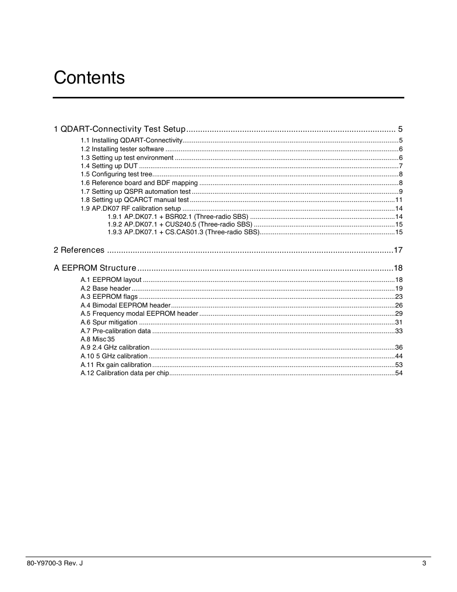
1 QDART-Connectivity Test Setup .......................................................................................... 5
1.1 Installing QDART-Connectivity................................................................................................................... 5
1.2 Installing tester software ............................................................................................................................ 6
1.3 Setting up test environment ....................................................................................................................... 6
1.4 Setting up DUT .......................................................................................................................................... 7
1.5 Configuring test tree ................................................................................................................................... 8
1.6 Reference board and BDF mapping .......................................................................................................... 8
1.7 Setting up QSPR automation test .............................................................................................................. 9
1.8 Setting up QCARCT manual test ............................................................................................................. 11
1.9 AP.DK07 RF calibration setup ................................................................................................................. 14
1.9.1 AP.DK07.1 + BSR02.1 (Three-radio SBS) ............................................................................. 14
1.9.2 AP.DK07.1 + CUS240.5 (Three-radio SBS) ........................................................................... 15
1.9.3 AP.DK07.1 + CS.CAS01.3 (Three-radio SBS)........................................................................ 15
2 References ........................................................................................................................... 17
A EEPROM Structure .............................................................................................................. 18
A.1 EEPROM layout ...................................................................................................................................... 18
A.2 Base header ............................................................................................................................................ 19
A.3 EEPROM flags ........................................................................................................................................ 23
A.4 Bimodal EEPROM header ....................................................................................................................... 26
A.5 Frequency modal EEPROM header ........................................................................................................ 29
A.6 Spur mitigation ........................................................................................................................................ 31
A.7 Pre-calibration data ................................................................................................................................. 33
A.8 Misc 35
A.9 2.4 GHz calibration .................................................................................................................................. 36
A.10 5 GHz calibration ................................................................................................................................... 44
A.11 Rx gain calibration ................................................................................................................................. 53
A.12 Calibration data per chip ........................................................................................................................ 54
80-Y9700-3 Rev. J
3
�
IPQ4018/IPQ4019/IPQ4028/IPQ4029 QDART Connectivity User Guide
Contents
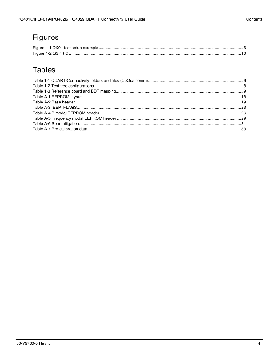
Figures
Figure 1-1 DK01 test setup example .............................................................................................................................. 6
Figure 1-2 QSPR GUI .................................................................................................................................................. 10
Tables
Table 1-1 QDART-Connectivity folders and files (C:\Qualcomm) ................................................................................... 6
Table 1-2 Test tree configurations .................................................................................................................................. 8
Table 1-3 Reference board and BDF mapping............................................................................................................... 9
Table A-1 EEPROM layout........................................................................................................................................... 18
Table A-2 Base header ................................................................................................................................................ 19
Table A-3 EEP_FLAGS ............................................................................................................................................... 23
Table A-4 Bimodal EEPROM header ........................................................................................................................... 26
Table A-5 Frequency modal EEPROM header ............................................................................................................ 29
Table A-6 Spur mitigation ............................................................................................................................................. 31
Table A-7 Pre-calibration data ...................................................................................................................................... 33
80-Y9700-3 Rev. J
4
�
1 QDART-Connectivity Test Setup
QDART-Connectivity is a collection of software tools and resources designed to aid original
equipment manufacturers with hardware development and production issues. The QDART-
Connectivity collection includes several tools:
■ Qualcomm® Atheros Manufacturing Support Library (QCAMSL)
■ Qualcomm Atheros Radio Control Tool (QCARCT)
■ Qualcomm Sequence Profiling Resource (QSPR)
■ QSPR subsystem test libraries and extensible test tree files (XTTs).
User credential is required to access CreatePoint site https://createpoint.qti.qualcomm.com/.
Contact Qualcomm® Technologies at support.cdmatech@qti.qualcomm.com if any questions or
issues with the access.
1.1 Installing QDART-Connectivity
Before start, make sure older version has been uninstalled completely from the workstation.
1. Download QDART-Connectivity from CreatePoint.
QDART-Connectivity release package can be downloaded at CreatePoint > Tools >
Qualcomm Development Acceleration Resource Toolkit – Connectivity. Make sure the
latest version is used for testing and calibration.
2. Make sure Microsoft .NET Framework 4 is installed on the Windows-based workstation.
3. Install QDART-Connectivity.
a. Unzip the QDART-Connectivity package.
b. Right click QDART-Connectivity.exe and select Run as administrator.
c. Click through to accept license agreement.
d. Select Complete mode to install.
When the installation is complete, QDART-Connectivity utilities such as QCARCT, QMine, and
QSPR are installed at C:\Program Files (x86)\Qualcomm. DLL files are located at
C:\Program Files (x86)\Qualcomm\bin.
A folder structure is created at C:\Qualcomm containing the testing files, tester configurations,
and reports/logs. Table 1-1 lists some of the folders and files that are configured or used during
setup, testing, and calibration.
80-Y9700-3 Rev. J
5
�
IPQ4018/IPQ4019/IPQ4028/IPQ4029 QDART Connectivity User Guide
QDART-Connectivity Test Setup
Table 1-1 QDART-Connectivity folders and files (C:\Qualcomm)
QMINE\Temp
QSPR\Testlog
WCN\ProdTests\BIN
WCN\ProdTests\CLPC
Excel files generated when QMine creates plots from test logs
Log files of QSPR
DLL files
External coupler testing files
WCN\ProdTests\QMineFormatDescriptors QMine files
WCN\ProdTests\refDesigns\
WCN\ProdTests\StationCal
WCN\ProdTests\TesterConfig
WCN\ProdTests\Test Trees
Board data files referenced by the WlanLoadDut properties
within each TestTree.xml file for loading DUT.
Pathloss for specific test instrument referenced by
InitializeWlanTester in TestTree.xml.
QSPR tester configuration (including tester type and IP
address) referenced by InitializeWlanTester in TestTree.xml.
The test trees (.xtt) files reference many of the above
directories for information/files/data.
1.2 Installing tester software
Contact tester vendor for installation documents and support.
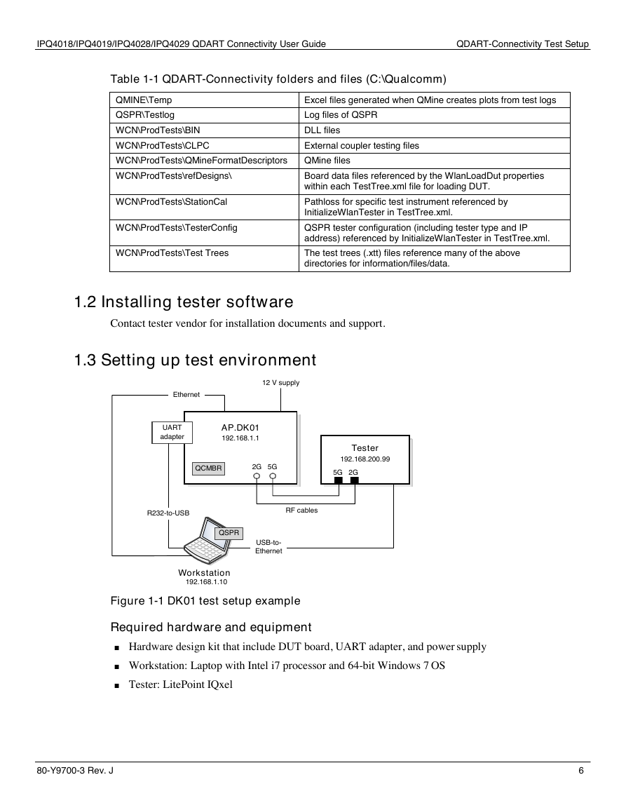
1.3 Setting up test environment
Ethernet
12 V supply
UART
adapter
AP.DK01
192.168.1.1
QCMBR
2G 5G
Tester
192.168.200.99
5G 2G
R232-to-USB
RF cables
QSPR
USB-to-
Ethernet
Workstation
192.168.1.10
Figure 1-1 DK01 test setup example
Required hardware and equipment
■ Hardware design kit that include DUT board, UART adapter, and power supply
■ Workstation: Laptop with Intel i7 processor and 64-bit Windows 7 OS
■ Tester: LitePoint IQxel
80-Y9700-3 Rev. J
6
�
IPQ4018/IPQ4019/IPQ4028/IPQ4029 QDART Connectivity User Guide
QDART-Connectivity Test Setup
IP addresses
■ Workstation QSPR Ethernet port IP: 192.168.1.10
■ Workstation USB2Ethernet port IP: 192.168.200.100
■ LitePoint IP: 192.168.200.99
■ DK01 Ethernet IP: 192.168.1.1
DUT console ports
■ Instance 0 (or device 0): 2390
■ Instance 1 (or device 1): 2391
1.4 Setting up DUT
Following is an example to set up AP.DK01 with IPQ4019.
1. Boot the DUT to get QSDK up and running.
2. Show wireless status.
uci show wireless
If wireless.wifi0.disabled or wireless.wifi1.disabled is 1, set it to 0.
uci set wireless.wifi0.disabled=0
uci set wireless.wifi1.disabled=0
3. Set DUT IP address and commit the address. Make sure the DUT and the workstation are
under the same subnet.
uci set network.lan.ipaddr=192.168.1.1
uci commit network
4. Turn off Wi-Fi.
wifi down
5. Start QCMBR.
/etc/init.d/qcmbr start
This command run Dual Band Dual Concurrent (DBDC) on the DUT using the command:
□ 2 GHz only:
/usr/sbin/Qcmbr -instance 0 -pcie 0
□ 2 GHz and 5 GHz:
/usr/sbin/Qcmbr -instance 0, 1 -pcie 0, 1
Other useful commands
■ Restart QCMBR
/etc/init.d/qcmbr restart
■ Run QCMBR with console prints:
/lib/firmware/IPQ4019/hw.1# kill
/lib/firmware/IPQ4019/hw.1# kill
ps
80-Y9700-3 Rev. J
7
�
IPQ4018/IPQ4019/IPQ4028/IPQ4029 QDART Connectivity User Guide
QDART-Connectivity Test Setup
/usr/sbin/Qcmbr -instance 0 –pcie 0 &
/usr/sbin/Qcmbr –instance 1 –pcie 1 &
1.5 Configuring test tree
Sample test tree is provided in the DP25 package. It is recommended to use QSPR GUI to edit
test tree (*.xtt) and use Notepad++ to modify configuration files (*.xml). During the
configuration, make sure correct file names and paths are provided in the test tree.
1. Download DP25 package from CreatePoint > Hardware Document >
IPQ4018/IPQ4028/IPQ4019/IPQ4029.
2. Copy the sample test tree (*.xtt) to WCN\ProdTests\Test Trees.
3. Configure the test tree parameters in Table 1-2 accordingly.
Table 1-2 Test tree configurations
InitializeWlanTester Parameters
testerConfigFileName
Reference to TesterConfigFile which contains the tester name.
stationCalFileName
Reference to StationCalFile which contains the pathloss information listed in
TxStationCalPath.
TxStationCalPath
RxStationCalPath
Names of the chains defined in the StationCalFile. Following is a naming
example:
BHx_device, where x = chain number, device = LP (LitePoint) or GLDN
(Golden). For example: BH0_LP and BH1_LP
ConnectDutUsingUserTranspportDLL
Type
wlanID
comport
1 QLIB_TARGET_TYPE_APQ
4019
192.168.1.1 (for Remote or Network port)
userTransPortDll
QMSL_WLAN_Transport.dll (Qmissle)
WlanLoadDut
DevDLLName
refDesign
eepFname
ipq4019
ipq4019
C:\\boardData\fakeBoardData_ipq4019.bin
iNVMemOption
5 DataFile
ssid
0x40
1.6 Reference board and BDF mapping
Before running the IPQ40xx reference boards in Mission mode, perform calibration for the
boards first. If reference board is not calibrated, the Host driver in Mission mode cannot select the
correct BDF automatically and always uses boarddata_0/1.bin. In this case, user must copy the
correct BDF to boarddata_0/1.bin according to Table 1-3.
80-Y9700-3 Rev. J
8
�


 2023年江西萍乡中考道德与法治真题及答案.doc
 2012年重庆南川中考生物真题及答案.doc
 2013年江西师范大学地理学综合及文艺理论基础考研真题.doc
 2020年四川甘孜小升初语文真题及答案I卷.doc
 2020年注册岩土工程师专业基础考试真题及答案.doc
 2023-2024学年福建省厦门市九年级上学期数学月考试题及答案.doc
 2021-2022学年辽宁省沈阳市大东区九年级上学期语文期末试题及答案.doc
 2022-2023学年北京东城区初三第一学期物理期末试卷及答案.doc
 2018上半年江西教师资格初中地理学科知识与教学能力真题及答案.doc
 2012年河北国家公务员申论考试真题及答案-省级.doc
 2020-2021学年江苏省扬州市江都区邵樊片九年级上学期数学第一次质量检测试题及答案.doc
 2022下半年黑龙江教师资格证中学综合素质真题及答案.doc