REVIEW QUEsTl0Ns
Chapter2 Diode CircuⅡ s
111
lVhat characteristic of a diodc is used in the dcsign of diode signal proccssing
r
’
〓
c△ cu⒒ s?
n
e
r
t
e
d
曩
躔
p
n
t
o
κ
)
n
.
吵
晋
|uC
10t
Jst
as
en
`i11
Ch
hc
;a1
ler
n-
二 Describc a simp1c ha1f-、 vavc diode rectincr circuit and skctch tllc Output vo1tage
Ⅴersus t1mc.
∶ Describc a siInp1e fuI1-wave diode rcctiner circuit and sketch the output Voltage
Ⅴersus timc.
三 VVhat is the advantage of connecting an RC nlter t。 tllc Output of a diode rccti-
ner circuit?
J Denncr匀 pple vo1tage。 How can the magnitude ofthc ripple voltage be rcduced?
- Describe a simple Zencr diode vo1tage reference circuit。
ˉ
、、厂hat Cfect does the Zcner diodc rcsistance haⅤ e on the voltage referencc circuit
opcration?lDe丘 ne load regulation.
3~ lVhat are the genera1characteristics of diode c1ippcr circuits?
; Dcscribe a sirnpIe diodc c1ippcr circuit that lirnits the negativc portion of a sinu-
soida1input vo1tage to a specincd va1ue。
∶0 V1厂hat are the general charactcristics of diodc c1amper circuits?
l二 lVhat one circuit c1cment, bcsides a diodc, iβ present in a11 diode clamper
cicu⒒ s?
12 Dcscribe the proccdure uscd in the anralysis of a circuit containing t、 vo diodcs
How many initia1assumptions conccming tlle state of the circuit are possib1c?
13 Dcscribe a diode OR1ogic circuit,Compare a1ogic1value at the output com-
pared to a1ogic1va1ue atthe input.Arethey the samc va1ue?
l亠 DcscⅡ be a dodc AND log妃 c虹 cuit Colllpare a log⒗ O value atthe output com-
pared to a logic0Ⅴa1ue atthe input Are they thc samc value?
15 Dcscribe a siFnp1c circuitthat can bc used to tum an IjED on or of、 vith a high
or lo、 v input vo1tage。
PRO:LEMs
「
:Xote∶ In thc№ llowing problems,assume勺 =0unless othcrwis9speoned,]
section2.1 Redfier CIrcu⒒ s
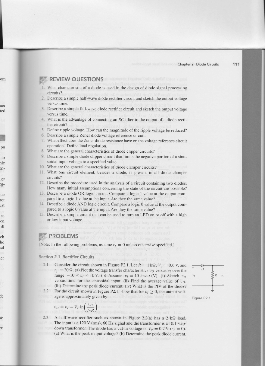
21 Considcr tlle circ缸t shown血 Figu£ P2.1Let R=1kΩ ,Vr/=0,6Y and
I'=20Ω (a)Plot山 e voltage“ ansfer characteⅡ stks vε vesus v'ovcr tllC
△mge-10兰 vr兰 IO V(b)Assumc vF=10sin
ω r(V)。 (i)SkCtch v。
ve1sus time for tllc蚯 nus⒍dd i11ptIt (io Find tlle average valuc of v@.
(iii)DCtC∏nine thc peak diode cuⅡ cnt (iv)What is the PIV of thc diode?
22 For thc circu⒒ shown in Figure P2,1,show that for vJ≡ 0,thC Output volt-
agc is approximatc1y givcn by
Figure P2,1
V@=叻 -
n巧
丶
/
f
l
\
l
J
/竺
w
2.3 A ha1iwave rcctiner such as shown in Figure2,2(a)has a2kΩ load,
Thc inputis a120V(mns),60Hz signal and山 c订ansforlllcr`a10∶ 1step-
down“ aIlsfom⒃⒈Tlle dode h凼 a cut~in volta罗 of‰ =0· 7V(勺 =0),
(a)Whatis the peak output voltagc?(b)Detennnine the pe岔 k diode current。
�
1日 2
Part1 semicondudor Devices and Basic App"cati° ns
2,4
2.5
(c)What is曲 e frac吐 on ω∝cent)of a cyc1e that vε >0。 (Φ Determine the
aVerage output vo1tagc (c)Find the average cuⅡ entin the1oad。
Con蚯 der the brdtteγ char鲈 ng c△ c"t shown血 F熄ure2.4(a)Assume that
yB=9V ys=15Y and
ω =2万 (60).(⑻ DCteⅡ mne the Value of R such
thatthe aVerage battery charging currentis氵 D=0.8A.(b)Find the fraction
of dme thatthe cⅡ ode is conducting。
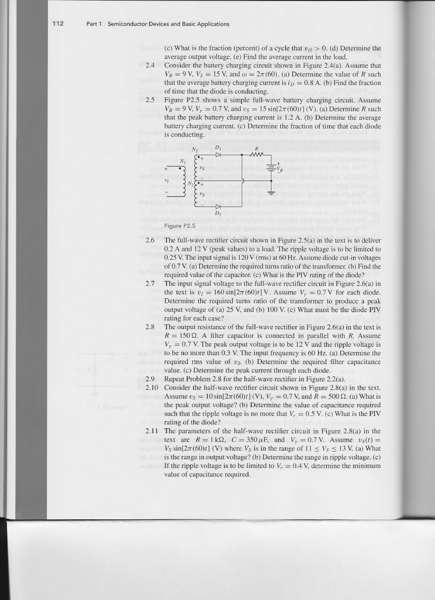
Figure P2.5 sho、 vs a siInp1e fu11-wave battery charging circuit。 Assume
‰ =9、 ‰ =⒍ 7、 and vs=15sin[2万 (60)r]α),(a)Detemine R sLlch
th肫 the peak b·dttcry charging cLlrrent“ ⒈2A.O)Detemine the ax/erage
ba钆 ery ch盯ging cuⅡent.o)Deterlllhe the fracdon oftime that each dode
is conducting.
D1
Ⅳ
1
屿
彐
Figure P2.5
2.6
2,7
28
2.9
2,10
The fu1⒈ waVe recjner c廿 cu⒒ shown h F瑭 ure2.5(⒆ in the text k to delher
0.2A and12V(pe·dk v缸ues)to a1oad.The⒒pp1e vo1tage is to bc1i血 ted to
0.25V Theinputs圯 nal。 120Ⅴ 【l△n9扯 60Hz,Assume dode cut-in voltages
of0.7Vo)Detαmine the req证 red mnsI血 o of曲 e transfom∝ lb)Find the
requ△ ed Value of仇 e capac姒觅 O)Ⅵ△rat o the PIV mung。f仇e山 ode?
The input signa1voltage to the fuⅡ wave recdner circu⒒ in Figure2,6(a)in
the text^vr=160sh⒓ 万“Ol莎 ]Ⅴ .As阢 me‰ =0· 7Ⅴ for each dode。
DeteⅡ nine the required tums rauo of the transfomcr to produce a pe犭 k
output voltage of(ω 25V and(b)100V(c)VVhat must bc thc dodc PIV
rating for each casc?
The output rcsistancc ofthc fu11-wave recunerin F坨 urC26(a)in thC tCxt is
R=150Ω 。An1tcr capac⒒ or is connected in para11c1with R.Assume
‰ =0· 7v ThC pcak output vo1tage`to be12V and山 c ripplc vo1tagc`
to bc no more than0.3V The input frequency is60Hz。 (a)Deter而 nc伍 e
rcquicd rms va1ue of Vs,(b)DeteⅡ 匝ne thc required n1ter capaotance
Va1ue.(c)DeterInine the peak cLlrrent through each diode,
Repeat ProbIem2.8forthe haliwaVe recdnerin F屯 ure2.∝ a)
Consider d1e ha1iwaVe rectiner circuit shown in Figure2.8(a)in the text.
Assume vs=10sin[2万 ∞ Q)扌 ](V),‰ =⒍ 7、 alld R=sO0Ω 。(a)Whatis
the peak output Voltage?(b)Deterrnine the value of capacitance required
such that the ripple voltage is no more that砗 =0,5V。 o)Ⅵ△at is the PIV
rating of the diode?
2.11 The parameters of the ha1⒈ wave rccti丘er circuit in Figure2.8(a)in the
text are R=1kΩ , C=350u只 and ‰ =0·7v Assume vs(莎 )=
V愆 ⒍nlzJT(6⑴ 莎](V)whCre ys is in the range of11兰 ys兰 13Vo)What
o the range in output volt· age?lb)DeteⅡmne由 e range in npple voltage。 rc)
If thc五pple voltagc is to be Ⅱ臼血ed to⒕ =0.4V deteⅡ Ⅲne the血 nimum
va1uc of capacitancc rcquircd.
�
△e thc
c that
such
】Ct1on
sume
such
cragc
diodc
·hvcr
ed to
∶agcs
d tllc
a)in
odc,
peak
PIV
xt is
umc
ge1s
)dhe
1ncc
ιe
x
t
.
洫
i
r
c
d
Ρˉv
the
)=
厂hat
(c)
1um
Chapter2 Diode Circu"s
113
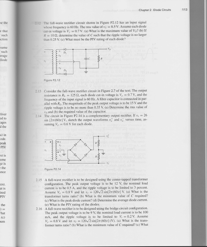
l i 丁he血 l1-wave recti丘 cr circuit shown in Figurc P2,12has an input signa1
示hosc frequency is60IIz,Thc Itns va1ue of vs=8,5V Assume each diode
:ut-in vdtage is‰ =0· 7v.(⒆ Wh·at is山e maximum Ⅶ1uc of%?(bl If
R= 10Ω ,determinc山 e va1uc of(· such that the ripple voltage is no largcr
△m025V(c)What must be the PIV rating of each modc?
%
c一
一
ˉ—
R
+乞
Vs
i
+
丶
一
D
2
门
Figure P2.12
Considcr the fu11-waⅤ e rectincr circuit in Figure27of thc text The output
rcsistancc is Rz=125Ω ,each dodc cut-in voltagc`‰ =07v,and tllc
frcquency ofthe input signa1is60Hz An1ter capacitor is connccted in par-
a11c1witll RL,The n1agnitude oftlle pcak output vo1tage isto be15V and the
Hpple voltage is to bc no more tllan035V(al Det∝ mine the rms valuc of
1· s and(b)the requircd value of the capacitor.
The circuit in Figure P2.14is a comp1cmentaγ output recti丘 cr.If vs==26
sh⒓ 万6Olr]V,sktc· ll tlle outpLlt Wavcforms v产 al△ dv歹 vCrsLls time,a⒌
suΠⅡng‰ =⒍ 6V for cach山 odc
Figure P2.14
215 A fu11-、 vaⅤ e rectiner is to be dcsigncd using the centcr-tappcd transformcr
con丘 guration The peak output Vo1tage is to be 12V thc noΠ Ⅱnal load
cuⅡ ent is to bc05卢、 and tllc ripp1c Ⅴoltagc is to bc1imitcd to3percent.
Asmmc‰ =0.8Ⅴ alld let tf=120√Ξs血 [2万 ∞o)r]V ra)w№ t is tllc
饣aljsformer turns ratio?rb)、 汛严h·dt诋 the minimum value of C required?
(c)Ⅸ′atis the pc迂 酞dode currcnt?(d)DCteⅡ 匝nc山 e avcrage diode cuⅡ ent,
(Cl Ⅵ%atis the PIV rating oftllc dodcs
216 A fuⅡ -wave rectincris to be designed using the bridge circuit connguration。
The pcak output vo1tage is to bc9ˇ ∶thC nomina11oad cuⅡ entis to bc100
mA,and tlle rⅡ ple voltagc is to bc1imitcd to 怖 =02V Assumc
‰ =08v al.d1ct vr=120√ Ξsin[2万 (60)r](V).Q)What k thC trans-
folIller tLlms mto?rb)what。 the minimum valuc of C req诬 ∞d?o)What
�
114
Port1 sen】 icondudor Devices and Basic AppⅡ cations
o the peak diode cuⅡent?ld)DeteⅡ m⒚e the average diode cuⅡ ent.(e)、 、冂Lat
is the PIV ra住 ng ofthe diodes。
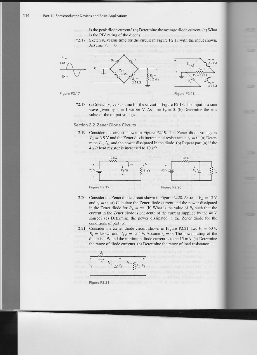
米2.17 sketch v@versus住 me for the circuit in Figure P2.17with the input shown。
A“ume V‰ =0.
Figure P2.17
Figure P2.18
米2.18 (a)Sketch v@versus time for the circu⒒ in Figurc P2.18。 The inputis a sinc
w⒏汜 gi妮n by叻 =10“ nω 莎V As叩 mc‰ =0。 O)Detem血 e the rms
va1ue ofthe output vo1tage
section2.2 zener E)iode(:″ cuits
2.19 Consider曲 c circuit shown in Figure P2.19.The zener diode vo1tage is
yz=3,9V andthe Zener dod0incremental re蛀 stance is△ =0,(a)Detcr-
血ne Jz,Jz,and the po、 ver dsslpated in the山 ode。 (1,)Repeat part o)if the
4kΩ 1oad resistor is increased to10kΩ
12⒑
120Ω
Figure P2.19
Figure P2.20
2.20 Consider me zcner diode circuitshGvn in Figure P2.20.Assume yz=12V
and饯 =0。 (a)Calcu1ate the zcn∝ dode current and the power dssipated
in the zener dode for RL=∞ .(b)W腕 t is the value of RL such that the
current in the zener diode is one-tcnth of the cuⅡ ent supp⒒ ed by the40V
source?O)DeteⅡmne the poWer do蚯 pated in由 e Zener dode for the
conditions of part(b)。
221 Consider the zen∝ 山ode ckcⅡt shown h Figure P2,21.Let yr=60V
Rj=150Ω ,and yz@=15.4V Assume饯 =0。 The power raung of the
dode is4W andthe mh⒒ mum dode cuⅡ entisto be15mA。 o)Det∝mine
the range of diode currents。 (b)Detemine the range of1oad resistance,
Figure P2.21
�
Chapter2 Diode Circuits
115
米222 In thc voltage rcgu1ator circu⒒ in Figure P2,21, yr:=2oˇ 1 Vz=10ˇ ∶
ˉ 0)DCt∝ mhe JI,Jz,alld rr,if
R氵 =222Ω ,and Pz(ma0=400汛
RL=380Ω 。(b)Determine thc valuc of RL that wi11cstab1ish Pz(max)in
tlle m。 de o)RCpc扯 p盯 tlb)if R氵 =175Ω ·
223 A Zencr diode is connectcd in a vo1tage regulator circuit as shown in Fig-
ure P2.21.The zcner vo1tage is yz==1o V and the Zener res^tance is
assumed to be rz=O ra)Determine tlle value of R氵 such that tlle Zen∝
diode rcmains in brcakdown if thc 1oad cuⅡ cnt varies from rL==5o to
500mA and if tl△ c inpLlt volnge v盯 ⒗s from yr=15to20V Assume
rz(m血 )=o.1rz(maxl,rb)Det∝ mine tlle power rat血 g∞ q“∞d for the
zener diode and the1oad resistor.
2,24 Consider伍 e zener chode crcuitin Figure219in the text Assume paralnct∝
valtles of yz@=5.6V (mode v。 ⒒agc when rz≡ o), △ =3Ω , and
R氵 =50Ω ,DcteⅡ mne VI,Jz,r.,and tl.c pow∝ dssipated h the山 ode for
(Θ yPs=10Y Rz=∞
RL=oo;alld ld)yPs=12V RL=200Ω .
;(b)yPs=10Y RL=200Ω
;rc)vPs=12Y
D2,25 Design a vo⒒ agc regu1ator crcuit such as sho、vn in Figure P221 sO tllat
Vz=7.5V mlc zen∝ diode vo1tage is yz=7.5V狨 rz=1oIllA The in-
crclnenta1 山odc resistance is rz==12Ω Tlle no洫 nal supp1y Vo1tage is
⒕ =12v alld tlle nO11nlldl load£ sistaIlce k RL=1kΩ .0)DC℃ Ⅱ匝ne R卜
lb)Ⅱ yr vancs by± 10p∝cellt,calCtll狨e tlle sourcc regula伍on.氓
`at is
tlle vaJiation in output Ⅴoltagc? (c) If RL v缸 Cs ov∝ the rangc of
1kζ2兰 RL兰 oo,what^the variation in output vo1tagc?Detcrl1unc tlle1ordd
regu1ation.
2.26 The perccnt regu1ation ofthe Zencr diode regu1ator shown in Figure2,16is
5percent The zcncr vo1tagc is Vlz@=6V and the zener re蛀 stance is
r之 ==3‘’ Also, the load rcsistancc Ⅴ舶 cs between 500 and 1000Ω , thc
input resistance is R氵 =280Ω ,and the∏1inimum powcr supply vo1tage is
yPs(min)=15V DeteⅡ吐ncthe maximum powcr supp1y vo1tage a11oWed.
扌227 A Vo1tagc rcgu1ator is to havc a nominal output voltage of10、 l Thc speci-
ned zener diodc has a ra伍 ng of1※、has a10V drop at Jz=25111A,and
has a Zencr resistance of rt==5Ω .The input power supply has a non1ina1
va1uc ofˇPs=20V and can vary by=± 25perccnt The output1oad cuⅡ ent
o to Ⅴary betwccn J‘ =0and20mA,o)r tllc minimum Zenσ cuⅡcnt`
to bc Jz=5mA,determinc the rcq“ ℃dRⅡ Φ)DeterIn血 ethc ma虹 mum
variation in output vo1忱 ge.o)Deterrmne tllc perccnt regu1ation
叮 28 ConsⅡ er tllc orcmtin Figurc P2,28Let V%=0ThC⒃ cond盯 y voltagc`
ghcn by vs=⒕ sin c,,莎 ,Wherc炼 =24V The zen∝ 山odc has p盯 amctcrs
yz=16V rat Ⅰz=40mA and rz=2Ω .Determinc R氵 such that the1oad
cm犯nt Can v盯 y ovcrthe nngc40兰 r.兰 40o mA witll Jz(min)=40IllA
and nnd c such thatthc ripp1e voltage is no1arger than1′ 11
‘
⒈
£
Ⅳ
¨e
d
屺
w
屺
)、
thc
1nc
Figure P2.28
�
116
Part1 semicondudor Devices and Basic App"cations
米2,29 Thc secondaΓ
`vo1tage in thc circuitin Figure P2.28is vs==12sin c/,莎
、l The
zener mode has paraltleters yz=8V荻 rz=10o mA alld严 z=O.5Ω 。Let
匕'=0and R氵 =3Ω ,Detcrlll血 e tlle percellt regt11aton for load cuⅡ ellts
bctween JL=0,2and1A Find C such thatthe ripp1e vo1tage is no1arger
than0.8、 1
section2.3 CⅡ pper and Clamper(△ rcuits
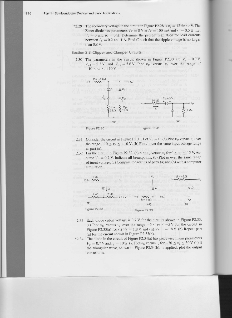
2.30 The parameters in the c△ cot shown in F熄 urc P2· 30a∞ lo=07Y
yzl=⒉ 3、 alld VIz2=⒌ 6VP1ot vo versus vr over山 c range of
-10兰 v'兰 +10V
R=05kΩ
ˇz=3v
Figure P2.30
Figure P2.31
2,31 Consider the circuit in Figurc P2.31,Let Vn/=0(a)P1ot v@versus V∫ ovcr
thc range-10兰 vr兰 +10V.(b)P1ot f10verthc same input vo1tage range
as pa⒒ (a).
2.32 Forthe c立 rcuit in Figurc P232,(a)p1ot vo versus vr for0兰 Vr 兰 15、 l As冖
阢 mC‰ =0· 7v Indicate沮 1b1· cakpoil△ ts tb)Plot rD Ovcr tl△ e saIne ral鸭 e
of订put voltagc.(Θ Compa⒑ thC rcsu1ts ofparts(al and(b)witl△ a computcr
sirnu1ation,
R=4kΩ
+15V tJ
R=4kΩ
(a)
Figure P2.32
Figure P2.33
2.33 Each diodc cut-in vo1tagc is0.7V for the circuits shown in Figurc P2.33。
(a)Plot vo versus vr over the rallge-5兰 vr兰 +5V for the⒍ rcuit h
Figure P2.33(ω for(i)Vl:=1· 8V and Ci)V1B=-18V rb)RepCat pa⒒
(a)for the circuit shown in Figure P2.33(b)
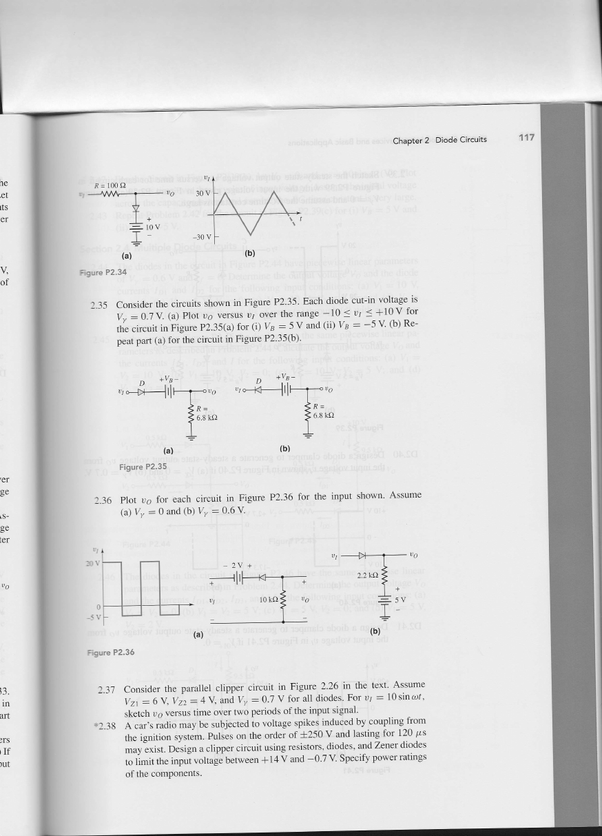
米2,34 The diode in the c△ cuit of Figure P2.34(a)has picce、 visc1inear parameters
‰ =⒍ 7v alld I尸 =10Ω ·o)Plot v@Ⅴ ersus vr for-30兰 tr兰 30V lb)If
曲e trhngu1盯 wave,shown in Figurc P2.34(b),is appⅡ cd,p1ot the output
versus tⅡ ne.
�
ChaPter2 Diode Circuits
R=100Ω
Fˉ gvre P2.34
2· 35
∶;:llⅧ∶莞∮1Ⅰ
peat part(ω br曲 eo∞证t in∏ gu⒑ P2,35(ω 。
忒C;臂i昱畲£圭犭堑苜∴萝∶:甘罕T
(D vr:=5v rdlld C0yB=-5V lb)R⒍
(a)
Figure P2.35
'
0
P1ot Vε for cach circuit in Figure
⑶ ‰ =O alld(b)‰ =⒍ 6v
P2,36 for thc input shown AssumC
=Igure P2.36
237 Considcr the para11e1 c1】 ppcr circuit in Figurc 226 in thC tCxt Assumc
lz1=6、 ‰ 2=4V and‰ =⒍ 7v for rd11⒍ odes For vJ=10sin ωr,
skctch v@versus ti1ne ovcr two pcriods ofthC input signa1,
兴238 A car’ s radio may be sut刂 c∝Cd to voltagc spikes induced by coupling f1· om
the ignition systcm。 Pu1scs on tlle order of=± 250V and1asting for120‘ ‘s
may exist.Dcsign a c1ipper circuit using resistors,diodes,and Zener diodes
to1imittllc input voltage bet△ l,ecn+14V alld一 O.7V Spco卸 poW∝ mtings
of tlle componellts,
h
c
`
c
t
ι
t
s
c
r
Y
o
f
q
g
e
L
s
.
g
e
ι
e
r
;
3
.
血
血
刈
旧
哑
�
118
Part1 semiconductor Devices and Basic App"cations
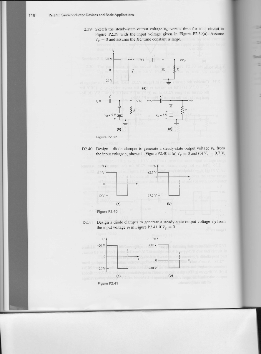
2.39 Sketch the steady-state output vo1tage vo Versus犭Lnc
Figure P2.39 Ⅵ汶曲 the input vo1tage given in Figure
y/=0and assumethe RC ume∞ nstant o large.
for each circuk h
P2.39(0)Assume
Vr
vr o-H
ta)
(
vo 叻 0-ˉ 丬
〓‰
一
V
+
十 ⊥
‰=5v二
Figure P2.39
D2.40 De⒍ gn a dode c1amper to generate a steady-state output vo1tage v@from
the i叩ut vo1tage vr血 own h∏ gure P2.40if0)‰ =0and(b)‰ =0·7v
Vo
+27V
0
-173V
Vr
+10V
0
=10V
(a)
F:gure P2.40
D2.41 De蛀 gn a dodc c1aInper to gcnerate a steady-state output vo⒒ age vo from
the i叫”t vo1tage Vrin Figwe P2.41if‰ =0.
Vr
+20Ⅴ
0
-20V
Figure P2.41
Vo
+30Ⅴ
0
-10V
—
l
I
l
巳
l
■
■
Ι
■
�



 2023年江西萍乡中考道德与法治真题及答案.doc
 2012年重庆南川中考生物真题及答案.doc
 2013年江西师范大学地理学综合及文艺理论基础考研真题.doc
 2020年四川甘孜小升初语文真题及答案I卷.doc
 2020年注册岩土工程师专业基础考试真题及答案.doc
 2023-2024学年福建省厦门市九年级上学期数学月考试题及答案.doc
 2021-2022学年辽宁省沈阳市大东区九年级上学期语文期末试题及答案.doc
 2022-2023学年北京东城区初三第一学期物理期末试卷及答案.doc
 2018上半年江西教师资格初中地理学科知识与教学能力真题及答案.doc
 2012年河北国家公务员申论考试真题及答案-省级.doc
 2020-2021学年江苏省扬州市江都区邵樊片九年级上学期数学第一次质量检测试题及答案.doc
 2022下半年黑龙江教师资格证中学综合素质真题及答案.doc