logo资料库

AB1562_Datasheet.pdf

第1页 / 共109页
第2页 / 共109页
第3页 / 共109页
第4页 / 共109页
第5页 / 共109页
第6页 / 共109页
第7页 / 共109页
第8页 / 共109页
资料共109页,剩余部分请下载后查看
Document Revision History
Features
Table of Contents
List of Figures and Tables
1 System Overview
1.1 Product series
1.2 System architecture
1.3 Platform features overview
1.3.1 Host processor DSP subsystem
1.3.2 Memory summary
1.3.3 Peripheral interfaces summary
1.3.4 Security
1.3.5 Others
1.4 Audio features overview
1.4.1 Audio codec feature overview
1.4.2 Audio other functions feature overview
1.5 Connectivity (Bluetooth) features overview
1.5.1 Bluetooth RF
1.5.2 Bluetooth baseband
1.6 Power management unit (PMU) features overview
1.7 Package
2 Functional Description
2.1 DSP Host Processor
2.1.1 Cadence® HiFi Mini®Audio Engine DSP coprocessor with HiFi EP® extension
2.1.1.1 Cadence® HiFi Mini®Audio Engine DSP coprocessor with HiFi EP® extension
2.1.1.2 Pipeline stages
2.1.2 Cache controller
2.1.2.1 Instruction Cache Details
2.1.2.2 Instruction Cache Details
2.1.3 Local Memory
2.1.4 Memory Management
2.1.5 Interrupt
2.2 Platform description
2.2.1
2.2.2 Boot mode
2.2.3 Trapping and mode selection
2.2.3.1 Trapping pin characteristics
2.2.3.2 Trapping timing diagram
2.2.4 Bus Architecture
2.3 Clock source and structure
2.3.1 Clock architecture
2.3.2 Digitally controlled crystal oscillator
2.3.3 32kHz low-speed internal RC (EOSC32)
2.3.4 Low-power oscillator (LPOSC)
2.3.4.1 Functional description
2.3.4.2 Functional specifications
2.3.5 Phase locked loop
2.3.5.1 Block description
2.3.5.2 Function specifications
2.4 Peripheral description
2.4.1 General purpose input/output (GPIO)
2.4.2 Direct memory access (DMA)
2.4.3 General purpose timer (GPT)
2.4.4 True random number generator (TRNG)
2.4.5 Real time clock (RTC)
2.4.6 Pulse width modulation (PWM)
2.4.7 Inter-integrated circuit controller (I2C)
2.4.8 Universal asynchronous receiver/transmitter (UART)
2.4.9 Serial peripheral interface (SPI)
2.4.9.1 SPI master controller
2.4.10 Serial flash controller (SFC)
2.5 Audio system
2.5.1 General descriptions
2.5.2 Audio codec
2.5.2.1 Audio uplink (Analog part)
2.5.2.1.1 Function description
2.5.2.1.2 Function specifications
2.5.2.2 Audio uplink digital filter
2.5.2.2.1 Overview
2.5.2.2.2 Specifications
2.5.2.3 Audio downlink (Analog part)
2.5.2.3.1 Function description
2.5.2.4 Audio downlink digital filter
2.5.2.4.1 Overview
2.5.2.4.2 Specifications
2.5.2.5 Side-tone filter
2.5.3 Asynchronous sample rate converter
2.5.4 Audio frontend memory interface
2.5.5 Audio inter connection
2.5.6 Audio hardware gain
2.5.7 Audio Up-sampler
2.5.8 Audio Down-sampler
2.5.9 Audio PLL frequency tuner
2.5.10 I2S
2.5.11 Active noise cancellation (ANC)
2.5.11.1 Feedforward ANC
2.5.11.2 Hybrid ANC
2.5.12 Audio system miscellaneous blocks
2.5.12.1 Audio IRQ counters
2.5.12.2 Voice Activity Detection
2.6 Connectivity System
2.6.1 Connectivity features overview
2.6.1.1 Bluetooth RF
2.6.1.2 Bluetooth Baseband
2.6.1.3 Bluetooth Core
2.6.2 Connectivity system
2.6.3 Modem
2.7 Analog Baseband
2.7.1 Low-power oscillator (LPOSC)
2.7.1.1 Functional description
2.7.1.2 Functional specifications
2.7.2 Phase locked loop
2.7.2.1 Block description
2.7.2.2 Function specifications
2.7.3 Auxiliary ADC (AUXADC)
2.7.3.1 Block description
2.7.3.2 Functional specifications
2.7.4 VAD (Voice amplitude detect)
2.7.4.1 Block description
2.7.4.2 Functional specifications
2.8 Capacitive Touch Control
2.8.1 Block description
2.8.2 Functional specifications
3 Bluetooth RF Subsystem
3.1 Bluetooth description
3.2 Functional specifications
3.2.1 Basic data rate – receiver specifications
3.2.2 Basic data rate – transmitter specifications
3.2.3 Enhanced data rate – receiver specifications
3.2.4 Enhanced data rate – transmitter specifications
3.2.5 Bluetooth LE – receiver specifications
3.2.6 Bluetooth LE – transmitter specifications
4 Power Management Unit and Low-Power Control System
4.1 Low-power control system
4.1.1 General descriptions
4.1.2 PMU architecture for low-power operating mode
4.1.3 Power performance summary
4.2 Power Management / Regulation
4.2.1 Introduction
4.2.2 BUCK regulator
4.2.3 LDO regulator
4.2.4 Power management unit (PMU)
4.2.5 Li-ion battery charger
5 Pin Description
5.1 AB1562 and AB1562A
5.1.1 AB1562 and AB1562A ball diagram
5.1.1.1 AB1562 and AB1562A pin coordination
5.1.1.2 AB1562 and AB1562A pin functions
5.1.2 AB1562 and AB1562A pin multiplexing
5.2 AB1561
5.2.1 AB1561 ball diagram
5.2.1.1 AB1561 pin coordination
5.2.1.2 AB1561 pin functions
5.2.2 AB1561 pin multiplexing
6 Electrical Characteristics
6.1 Absolute maximum ratings
6.1.1 AB1562 series
6.2 Power
6.2.1 VDD33 LDO
6.2.2 VRF11 LDO
6.2.3 VDIG18 LDO
6.3 Battery charger
6.4 Electrostatic discharge (ESD) ratings
6.5 Operating conditions
6.5.1 AB1562 series
6.5.1.1 General operating conditions
6.5.1.2 Input or output port characteristics
6.6 Peripheral interface
6.6.1 SPI master interface characteristics
7 Package Information
7.1 AB1562 series mechanical data of the package
loginid=bozzy@szdotop.com,time=2020-04-03 15:05:51,ip=113.89.41.164,doctitle=AB1562_Datasheet.docx,company= AB1562 Datasheet 0.13 Version: Release date: 20 March 2020 FOR bozzy@ szdotop.com USE ONLY AIROHA CONFIDENTIAL This document contains information that is proprietary to Airoha Technology Corp. (“Airoha”) and/or its licensor(s). Airoha cannot grant you permission for any material that is owned by third parties. You may only use or reproduce this document if you have agreed to and been bound by the applicable license agreement with Airoha (“License Agreement”) and been granted explicit permission within the License Agreement (“Permitted User”). If you are not a Permitted User, please cease any access or use of this document immediately. Any unauthorized use, reproduction or disclosure of this document in whole or in part is strictly prohibited. THIS DOCUMENT IS PROVIDED ON AN “AS-IS” BASIS ONLY. AIROHA EXPRESSLY DISCLAIMS ANY AND ALL WARRANTIES OF ANY KIND AND SHALL IN NO EVENT BE LIABLE FOR ANY CLAIMS RELATING TO OR ARISING OUT OF THIS DOCUMENT OR ANY USE OR INABILITY TO USE THEREOF. Specifications contained herein are subject to change without notice. © 2020 Airoha Technology Corp.
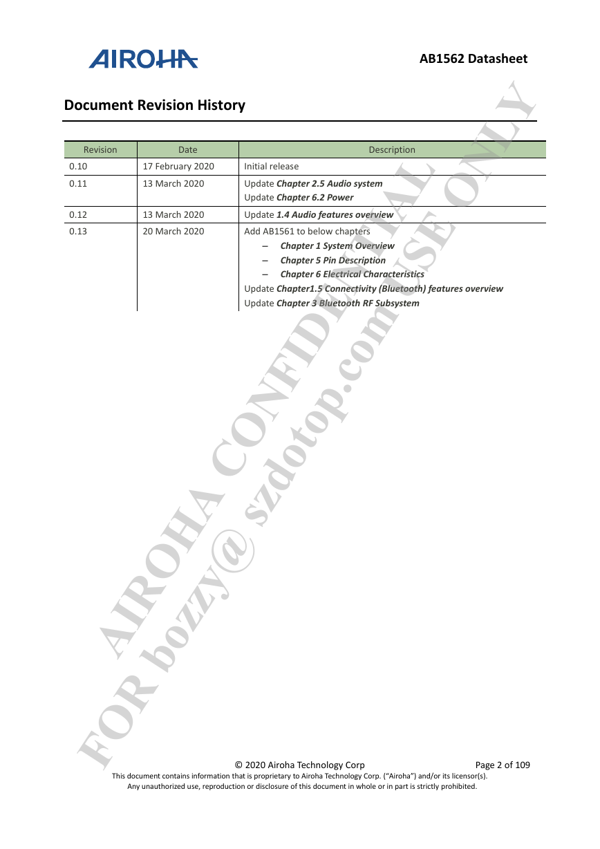
Document Revision History 0.10 0.11 0.12 0.13 AB1562 Datasheet Description 13 March 2020 13 March 2020 Revision Date 20 March 2020 Add AB1561 to below chapters 17 February 2020 Initial release Update 1.4 Audio features overview Update Chapter 2.5 Audio system Update Chapter 6.2 Power Update Chapter1.5 Connectivity (Bluetooth) features overview Update Chapter 3 Bluetooth RF Subsystem – Chapter 1 System Overview – Chapter 5 Pin Description – Chapter 6 Electrical Characteristics FOR bozzy@ szdotop.com USE ONLY AIROHA CONFIDENTIAL This document contains information that is proprietary to Airoha Technology Corp. (“Airoha”) and/or its licensor(s). © 2020 Airoha Technology Corp Page 2 of 109 Any unauthorized use, reproduction or disclosure of this document in whole or in part is strictly prohibited. loginid=bozzy@szdotop.com,time=2020-04-03 15:05:51,ip=113.89.41.164,doctitle=AB1562_Datasheet.docx,company=
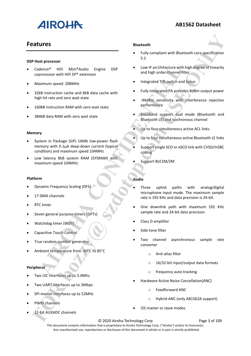
AB1562 Datasheet Engine DSP      Memory Features DSP Host processor  Maximum speed: 208MHz Integrated T/R switch and balun Bluetooth 384kB data RAM with zero wait state Bluetooth LE) and isochronous channel 160kB instruction RAM with zero wait state  Up to four simultaneous active ACL links Fully integrated PA provides 8dBm output power  Up to four simultaneous active Bluetooth LE links  Baseband support dual mode (Bluetooth and Fully compliant with Bluetooth core specification 5.2 Support single SCO or eSCO link with CVSD/mSBC coding Low-IF arc1hitecture with high degree of linearity and high order channel filter -94dBm sensitivity with interference rejection performance Cadence® HiFi Mini®Audio coprocessor with HiFi EP® extension 32kB instruction cache and 8kB data cache with high hit rate and zero wait state Low latency 8kB system RAM (SYSRAM) with maximum speed 104MHz System in Package (SiP) 16Mb low-power flash memory with 0.1µA deep-down current (typical condition) and maximum speed 104MHz FOR bozzy@ szdotop.com USE ONLY AIROHA CONFIDENTIAL uplink Three analog/digital microphone input mode. The maximum sample rate is 192 KHz and data precision is 24-bit. paths with  One downlink path with maximum 192 KHz  Hardware Active Noise Cancellation(ANC) channel asynchronous sample rate o 16/32-bit input/output data formats o Hybrid ANC (only AB1562A support) sample rate and 24-bit data precision. SPI master interfaces up to 52MHz Two UART interfaces up to 3Mbps This document contains information that is proprietary to Airoha Technology Corp. (“Airoha”) and/or its licensor(s).      © 2020 Airoha Technology Corp Page 3 of 109 Class D amplifier Side-tone filter Two I2C interfaces up to 3.4Mhz PWM channels 12-bit AUXADC channels True random number generator Two converter o Anti-alias filter  I2S master or slave modes o frequency auto-tracking Platform  Dynamic Frequency Scaling (DFS) Audio               17 DMA channels  RTC timer  Seven general purpose timers (GPTs)  Watchdog timer (WDT) Capacitive Touch Control  Ambient temperature from -40°C to 85°C Peripheral  Support BLE1M/2M o Feedforward ANC Any unauthorized use, reproduction or disclosure of this document in whole or in part is strictly prohibited. loginid=bozzy@szdotop.com,time=2020-04-03 15:05:51,ip=113.89.41.164,doctitle=AB1562_Datasheet.docx,company=
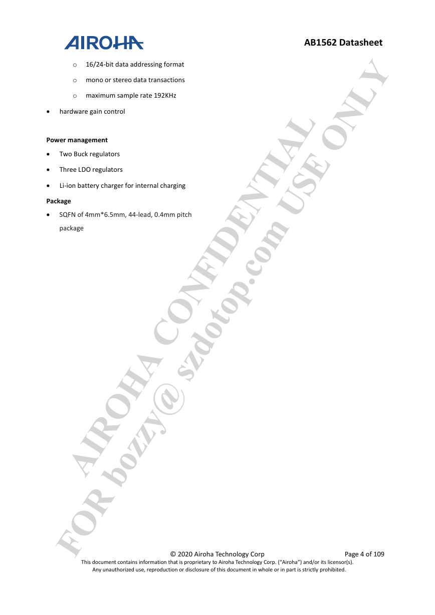
AB1562 Datasheet o maximum sample rate 192KHz Two Buck regulators Three LDO regulators o 16/24-bit data addressing format o mono or stereo data transactions Li-ion battery charger for internal charging SQFN of 4mm*6.5mm, 44-lead, 0.4mm pitch FOR bozzy@ szdotop.com USE ONLY AIROHA CONFIDENTIAL © 2020 Airoha Technology Corp Page 4 of 109      hardware gain control Power management Package package This document contains information that is proprietary to Airoha Technology Corp. (“Airoha”) and/or its licensor(s). Any unauthorized use, reproduction or disclosure of this document in whole or in part is strictly prohibited. loginid=bozzy@szdotop.com,time=2020-04-03 15:05:51,ip=113.89.41.164,doctitle=AB1562_Datasheet.docx,company=
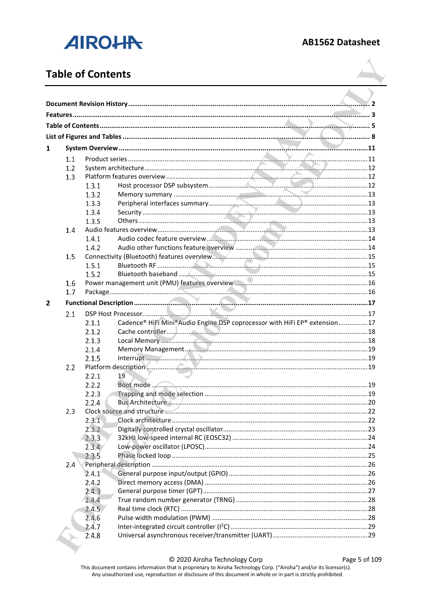
Table of Contents Document Revision History .............................................................................................................................. 2 Features ........................................................................................................................................................... 3 Table of Contents ............................................................................................................................................. 5 List of Figures and Tables ................................................................................................................................. 8 System Overview .................................................................................................................................. 11 Product series ................................................................................................................................... 11 System architecture .......................................................................................................................... 12 Platform features overview .............................................................................................................. 12 Host processor DSP subsystem ....................................................................................... 12 Memory summary .......................................................................................................... 13 Peripheral interfaces summary....................................................................................... 13 Security ........................................................................................................................... 13 Others ............................................................................................................................. 13 Audio features overview................................................................................................................... 13 Audio codec feature overview ........................................................................................ 14 Audio other functions feature overview ........................................................................ 14 Connectivity (Bluetooth) features overview..................................................................................... 15 Bluetooth RF ................................................................................................................... 15 Bluetooth baseband ....................................................................................................... 15 Power management unit (PMU) features overview ......................................................................... 16 Package ............................................................................................................................................. 16 Functional Description .......................................................................................................................... 17 DSP Host Processor ........................................................................................................................... 17 Cadence® HiFi Mini®Audio Engine DSP coprocessor with HiFi EP® extension................ 17 Cache controller .............................................................................................................. 18 Local Memory ................................................................................................................. 18 Memory Management .................................................................................................... 19 Interrupt ......................................................................................................................... 19 Platform description ......................................................................................................................... 19 FOR bozzy@ szdotop.com USE ONLY AIROHA CONFIDENTIAL 19 Boot mode ...................................................................................................................... 19 Trapping and mode selection ......................................................................................... 19 Bus Architecture ............................................................................................................. 20 Clock source and structure ............................................................................................................... 22 Clock architecture ........................................................................................................... 22 Digitally controlled crystal oscillator............................................................................... 23 32kHz low-speed internal RC (EOSC32) .......................................................................... 24 Low-power oscillator (LPOSC) ......................................................................................... 24 Phase locked loop ........................................................................................................... 25 Peripheral description ...................................................................................................................... 26 General purpose input/output (GPIO) ............................................................................ 26 Direct memory access (DMA) ......................................................................................... 26 General purpose timer (GPT) .......................................................................................... 27 True random number generator (TRNG) ........................................................................ 28 Real time clock (RTC) ...................................................................................................... 28 Pulse width modulation (PWM) ..................................................................................... 28 Inter-integrated circuit controller (I2C) ........................................................................... 29 Universal asynchronous receiver/transmitter (UART) .................................................... 29 © 2020 Airoha Technology Corp Page 5 of 109 AB1562 Datasheet This document contains information that is proprietary to Airoha Technology Corp. (“Airoha”) and/or its licensor(s). Any unauthorized use, reproduction or disclosure of this document in whole or in part is strictly prohibited. loginid=bozzy@szdotop.com,time=2020-04-03 15:05:51,ip=113.89.41.164,doctitle=AB1562_Datasheet.docx,company=
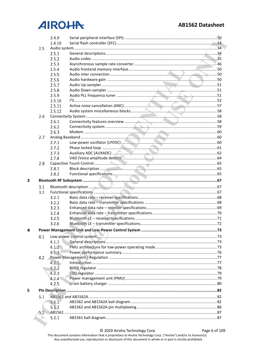
AB1562 Datasheet Serial peripheral interface (SPI) ...................................................................................... 30 Serial flash controller (SFC) ............................................................................................. 34 Audio system .................................................................................................................................... 34 General descriptions ....................................................................................................... 34 Audio codec .................................................................................................................... 35 Asynchronous sample rate converter ............................................................................. 46 Audio frontend memory interface .................................................................................. 50 Audio inter connection ................................................................................................... 50 Audio hardware gain ...................................................................................................... 50 Audio Up-sampler ........................................................................................................... 51 Audio Down-sampler ...................................................................................................... 51 Audio PLL frequency tuner ............................................................................................. 51 I2S .................................................................................................................................... 52 Active noise cancellation (ANC) ...................................................................................... 57 Audio system miscellaneous blocks ................................................................................ 58 Connectivity System ......................................................................................................................... 58 Connectivity features overview ...................................................................................... 58 Connectivity system ........................................................................................................ 59 Modem ........................................................................................................................... 60 Analog Baseband .............................................................................................................................. 60 Low-power oscillator (LPOSC) ......................................................................................... 60 Phase locked loop ........................................................................................................... 61 Auxiliary ADC (AUXADC) ................................................................................................. 62 VAD (Voice amplitude detect) ........................................................................................ 64 Capacitive Touch Control .................................................................................................................. 65 Block description ............................................................................................................ 65 Functional specifications ................................................................................................ 65 Bluetooth RF Subsystem ....................................................................................................................... 67 Bluetooth description ....................................................................................................................... 67 Functional specifications .................................................................................................................. 67 Basic data rate – receiver specifications ......................................................................... 68 Basic data rate – transmitter specifications ................................................................... 68 Enhanced data rate – receiver specifications ................................................................. 69 Enhanced data rate – transmitter specifications ............................................................ 70 Bluetooth LE – receiver specifications ............................................................................ 71 Bluetooth LE – transmitter specifications ....................................................................... 72 Power Management Unit and Low-Power Control System ................................................................... 73 Low-power control system ............................................................................................................... 73 General descriptions ....................................................................................................... 73 PMU architecture for low-power operating mode ......................................................... 73 Power performance summary ........................................................................................ 76 Power Management / Regulation .................................................................................................... 77 Introduction .................................................................................................................... 77 BUCK regulator ............................................................................................................... 78 LDO regulator ................................................................................................................. 79 Power management unit (PMU) ..................................................................................... 79 Li-ion battery charger ..................................................................................................... 80 Pin Description ..................................................................................................................................... 82 AB1562 and AB1562A ....................................................................................................................... 82 AB1562 and AB1562A ball diagram ................................................................................ 82 AB1562 and AB1562A pin multiplexing .......................................................................... 86 AB1561 ............................................................................................................................................. 87 AB1561 ball diagram ....................................................................................................... 87 FOR bozzy@ szdotop.com USE ONLY AIROHA CONFIDENTIAL This document contains information that is proprietary to Airoha Technology Corp. (“Airoha”) and/or its licensor(s). Any unauthorized use, reproduction or disclosure of this document in whole or in part is strictly prohibited. loginid=bozzy@szdotop.com,time=2020-04-03 15:05:51,ip=113.89.41.164,doctitle=AB1562_Datasheet.docx,company= © 2020 Airoha Technology Corp Page 6 of 109
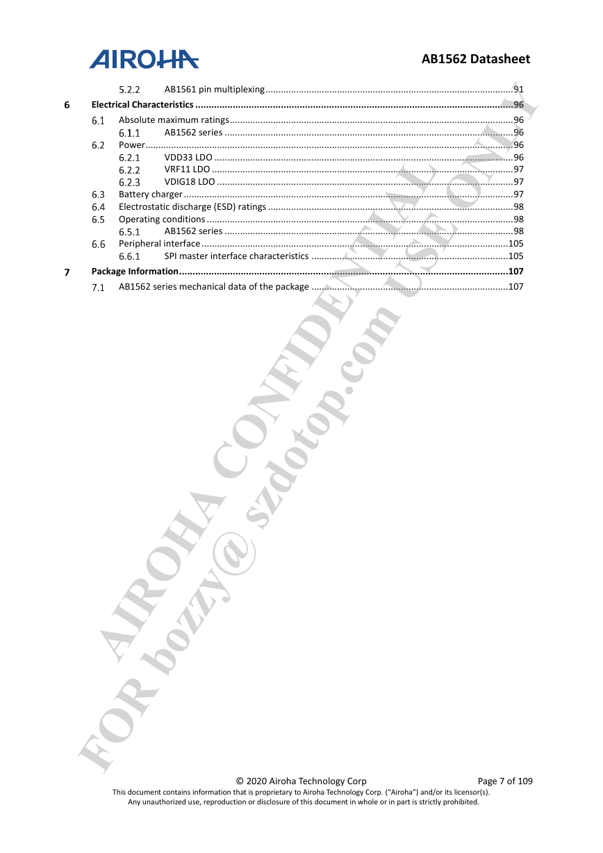
AB1562 Datasheet AB1561 pin multiplexing ................................................................................................. 91 Electrical Characteristics ....................................................................................................................... 96 Absolute maximum ratings ............................................................................................................... 96 AB1562 series ................................................................................................................. 96 Power ................................................................................................................................................ 96 VDD33 LDO ..................................................................................................................... 96 VRF11 LDO ...................................................................................................................... 97 VDIG18 LDO .................................................................................................................... 97 Battery charger ................................................................................................................................. 97 Electrostatic discharge (ESD) ratings ................................................................................................ 98 Operating conditions ........................................................................................................................ 98 AB1562 series ................................................................................................................. 98 Peripheral interface ........................................................................................................................ 105 SPI master interface characteristics ............................................................................. 105 Package Information ........................................................................................................................... 107 AB1562 series mechanical data of the package ............................................................................. 107 FOR bozzy@ szdotop.com USE ONLY AIROHA CONFIDENTIAL © 2020 Airoha Technology Corp Page 7 of 109 This document contains information that is proprietary to Airoha Technology Corp. (“Airoha”) and/or its licensor(s). Any unauthorized use, reproduction or disclosure of this document in whole or in part is strictly prohibited. loginid=bozzy@szdotop.com,time=2020-04-03 15:05:51,ip=113.89.41.164,doctitle=AB1562_Datasheet.docx,company=
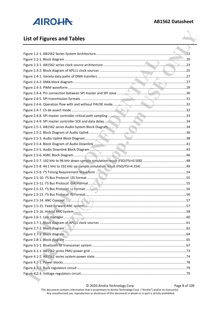
List of Figures and Tables FOR bozzy@ szdotop.com USE ONLY AIROHA CONFIDENTIAL Figure 1.2-1. AB1562 Series System Architecture ................................................................................................. 12 Figure 2.2-1. Block diagram .................................................................................................................................. 20 Figure 2.3-1. AB1562 series clock source architecture ......................................................................................... 23 Figure 2.3-2. Block diagram of APLL1 clock sources ............................................................................................. 25 Figure 2.4-1. Variety data paths of DMA transfers ............................................................................................... 27 Figure 2.4-2. DMA block diagram .......................................................................................................................... 27 Figure 2.4-3. PWM waveform ............................................................................................................................... 29 Figure 2.4-4. Pin connection between SPI master and SPI slave .......................................................................... 30 Figure 2.4-5. SPI transmission formats ................................................................................................................. 31 Figure 2.4-6. Operation flow with and without PAUSE mode ............................................................................... 32 Figure 2.4-7. CS de-assert mode ........................................................................................................................... 32 Figure 2.4-8. SPI master controller critical path sampling .................................................................................... 33 Figure 2.4-9. SPI master controller SCK and data delay ........................................................................................ 34 Figure 2.5-1. AB1562 series Audio System Block Diagram .................................................................................... 34 Figure 2.5-2. Block Diagram of Audio Uplink ........................................................................................................ 36 Figure 2.5-3. Audio Uplink Block Diagram............................................................................................................. 38 Figure 2.5-4. Block Diagram of Audio Downlink ................................................................................................... 41 Figure 2.5-5. Audio Downlink Block Diagram ........................................................................................................ 43 Figure 2.5-6. ASRC Block Diagram ......................................................................................................................... 46 Figure 2.5-7. 192 kHz to 96 kHz down-sample simulation result (FSO/FSI=0.500) ............................................... 48 Figure 2.5-8. 44.1 kHz to 192 kHz up-sample simulation result (FSO/FSI=4.354) ................................................. 49 Figure 2.5-9. I2S Timing Requirement Waveform ................................................................................................. 54 Figure 2.5-10. I2S Bus Protocol: I2S Format .......................................................................................................... 55 Figure 2.5-11. I2S Bus Protocol: EIAJ Format ......................................................................................................... 55 Figure 2.5-12. I2S Bus Protocol: LJ Format ............................................................................................................ 56 Figure 2.5-13. I2S Bus Protocol: RJ Format ............................................................................................................ 56 Figure 2.5-14. ANC Concept .................................................................................................................................. 57 Figure 2.5-15. Feed-forward ANC system ............................................................................................................. 57 Figure 2.5-16. Hybrid ANC system ........................................................................................................................ 58 Figure 2.6-1. Link manager .................................................................................................................................... 60 Figure 2.7-1. Block diagram of APLL1 clock sources ............................................................................................. 61 Figure 2.7-2. Block diagram .................................................................................................................................. 62 Figure 2.7-3. Block diagram .................................................................................................................................. 64 Figure 2.8-1. Block diagram .................................................................................................................................. 65 Figure 3.1-1. Bluetooth RF transceiver system ..................................................................................................... 67 Figure 4.1-1. AB1562 series PMU power grid ....................................................................................................... 73 Figure 4.1-2. AB1562 series system power state .................................................................................................. 74 Figure 4.2-1. Power blocks .................................................................................................................................... 78 Figure 4.2-2. Buck regulators circuit ..................................................................................................................... 79 Figure 4.2-3. Voltage regulators circuit ................................................................................................................. 79 © 2020 Airoha Technology Corp Page 8 of 109 AB1562 Datasheet This document contains information that is proprietary to Airoha Technology Corp. (“Airoha”) and/or its licensor(s). Any unauthorized use, reproduction or disclosure of this document in whole or in part is strictly prohibited. loginid=bozzy@szdotop.com,time=2020-04-03 15:05:51,ip=113.89.41.164,doctitle=AB1562_Datasheet.docx,company=
分享到:
收藏