logo资料库

ISG,CNC内核,Twin cat CNC.pdf

第1页 / 共664页
第2页 / 共664页
第3页 / 共664页
第4页 / 共664页
第5页 / 共664页
第6页 / 共664页
第7页 / 共664页
第8页 / 共664页
资料共664页,剩余部分请下载后查看
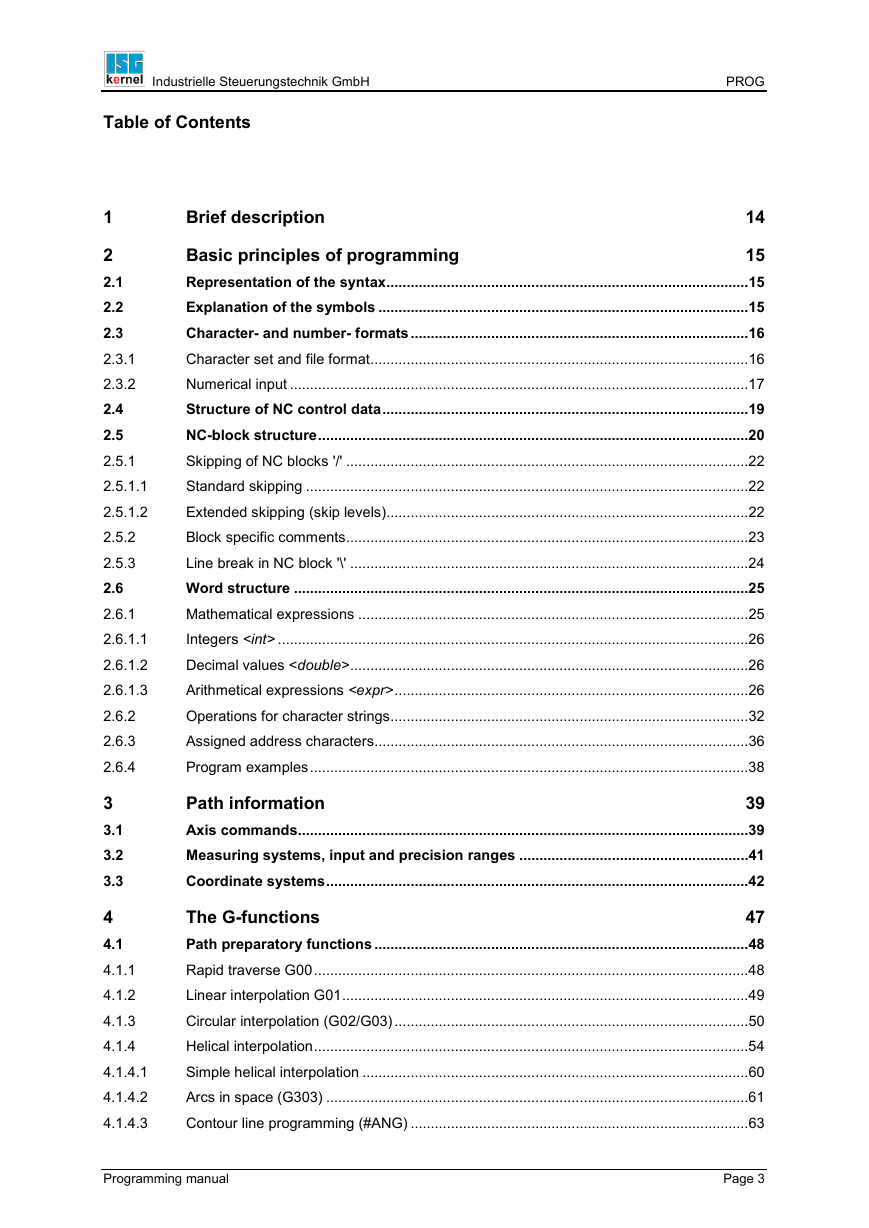
1 Brief description
2 Basic principles of programming
2.1 Representation of the syntax
2.2 Explanation of the symbols
2.3 Character- and number- formats
2.3.1 Character set and file format
2.3.2 Numerical input
2.4 Structure of NC control data
2.5 NC-block structure
2.5.1 Skipping of NC blocks '/'
2.5.1.1 Standard skipping
2.5.1.2 Extended skipping (skip levels)
2.5.2 Block specific comments
2.5.3 Line break in NC block '\'
2.6 Word structure
2.6.1 Mathematical expressions
2.6.1.1 Integers
2.6.1.2 Decimal values
2.6.1.3 Arithmetical expressions
2.6.2 Operations for character strings
2.6.3 Assigned address characters
2.6.4 Program examples
3 Path information
3.1 Axis commands
3.2 Measuring systems, input and precision ranges
3.3 Coordinate systems
4 The G-functions
4.1 Path preparatory functions
4.1.1 Rapid traverse G00
4.1.2 Linear interpolation G01
4.1.3 Circular interpolation (G02/G03)
4.1.4 Helical interpolation
4.1.4.1 Simple helical interpolation
4.1.4.2 Arcs in space (G303)
4.1.4.3 Contour line programming (#ANG)
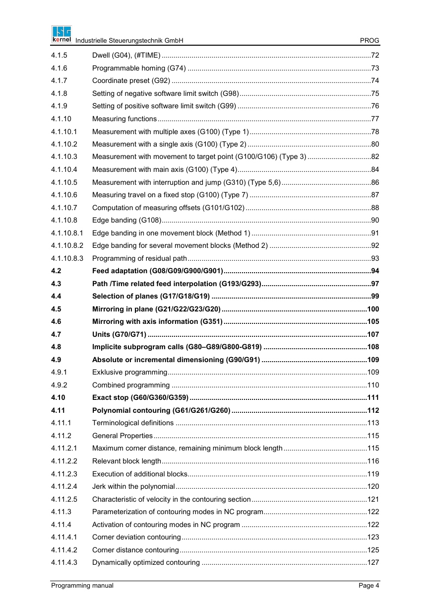
4.1.5 Dwell (G04), (#TIME)
4.1.6 Programmable homing (G74)
4.1.7 Coordinate preset (G92)
4.1.8 Setting of negative software limit switch (G98)
4.1.9 Setting of positive software limit switch (G99)
4.1.10 Measuring functions
4.1.10.1 Measurement with multiple axes (G100) (Type 1)
4.1.10.2 Measurement with a single axis (G100) (Type 2)
4.1.10.3 Measurement with movement to target point (G100/G106) (Type 3)
4.1.10.4 Measurement with main axis (G100) (Type 4)
4.1.10.5 Measurement with interruption and jump (G310) (Type 5,6)
4.1.10.6 Measuring travel on a fixed stop (G100) (Type 7)
4.1.10.7 Computation of measuring offsets (G101/G102)
4.1.10.8 Edge banding (G108)
4.1.10.8.1 Edge banding in one movement block (Method 1)
4.1.10.8.2 Edge banding for several movement blocks (Method 2)
4.1.10.8.3 Programming of residual path
4.2 Feed adaptation (G08/G09/G900/G901)
4.3 Path /Time related feed interpolation (G193/G293)
4.4 Selection of planes (G17/G18/G19)
4.5 Mirroring in plane (G21/G22/G23/G20)
4.6 Mirroring with axis information (G351)
4.7 Units (G70/G71)
4.8 Implicite subprogram calls (G80–G89/G800-G819)
4.9 Absolute or incremental dimensioning (G90/G91)
4.9.1 Exklusive programming
4.9.2 Combined programming
4.10 Exact stop (G60/G360/G359)
4.11 Polynomial contouring (G61/G261/G260)
4.11.1 Terminological definitions
4.11.2 General Properties
4.11.2.1 Maximum corner distance, remaining minimum block length
4.11.2.2 Relevant block length
4.11.2.3 Execution of additional blocks
4.11.2.4 Jerk within the polynomial
4.11.2.5 Characteristic of velocity in the contouring section
4.11.3 Parameterization of contouring modes in NC program
4.11.4 Activation of contouring modes in NC program
4.11.4.1 Corner deviation contouring
4.11.4.2 Corner distance contouring
4.11.4.3 Dynamically optimized contouring
4.11.4.4 Dynamically optimized contouring with lead axis
4.11.4.5 Interim point contouring
4.11.4.6 Dynamically optimized contouring of complete contour
4.11.5 Examples
4.11.6 Remarks
4.12 Corner deceleration
4.12.1 Setting the corner deceleration parameter values
4.12.2 Selection and deselection of corner deceleration (G12/G13)
4.13 Tool radius compensation (G40/G41/G42)
4.14 Selection/deselection methods of tool radius compensation (G138/G139/G237/G238/G239/G05)
4.15 Selection of the transition of tool radius compensation (G25/G26)
4.16 Feedrate adaptation for tool radius compensation (G10/G11)
4.17 Selection/deselection of contour masking by tool radius compensation (G141/G140)
4.18 Zero offsets NPV (G53/G54/...G59)
4.18.1 Enhanced Zero Offset Variables
4.18.2 Adding / Subtracting Offsets
4.18.3 Access to the current zero offset
4.18.4 Default zero offset
4.18.5 Creating zero offset groups
4.18.6 Extended zero offsets (G159)
4.18.7 Axes-related enabling/disabling of zero offset (G160)
4.19 Center point specification for circle definition (G161/G162)
4.20 Radius programming (R, G163)
4.21 Center point offset controlling (G164/G165)
4.21.1 Special function: circle radius compensation in combination with G164
4.22 Feedforward control (G135/G136/G137)
4.23 Weighting of maximum velocity (G128)
4.24 Weighting of rapid traverse velocity (G129)
4.25 Parameterization of acceleration profile
4.25.1 Acceleration weighting (G130/G131/G231)
4.25.2 Weighting the ramp times (G132/G133/G134/G233)
4.26 Machining time or feedrate (G93/G94/G95/G194)
4.27 Inserting of chamfers and roundings (G301/G302)
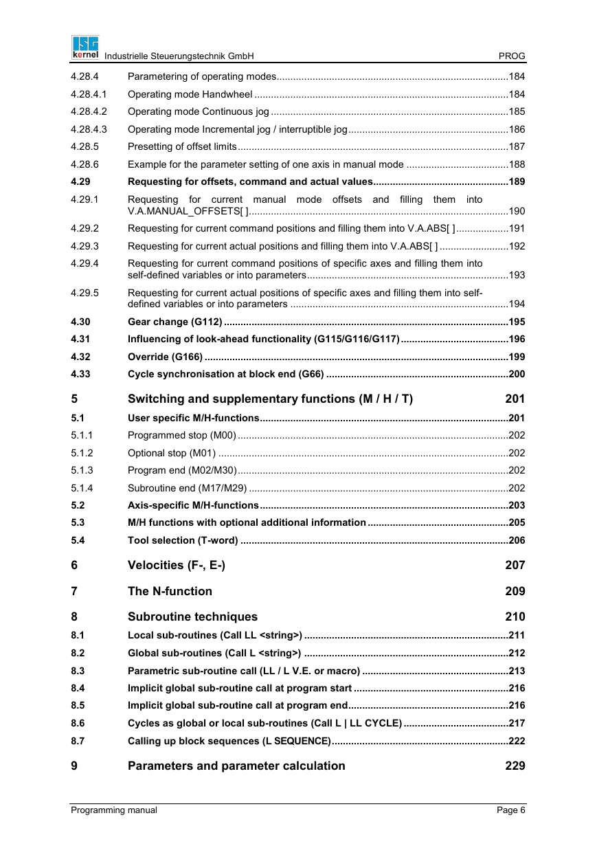
4.27.1 Inserting of chamfers on the example G301
4.27.2 Inserting of roundings on the example G302
4.28 Manual mode
4.28.1 Selection/deselection with parallel interpolation (G201/G202)
4.28.2 Selection without parallel interpolation (G200)
4.28.3 Program end (M02, M30)
4.28.4 Parametering of operating modes
4.28.4.1 Operating mode Handwheel
4.28.4.2 Operating mode Continuous jog
4.28.4.3 Operating mode Incremental jog / interruptible jog
4.28.5 Presetting of offset limits
4.28.6 Example for the parameter setting of one axis in manual mode
4.29 Requesting for offsets, command and actual values
4.29.1 Requesting for current manual mode offsets and filling them into V.A.MANUAL_OFFSETS[ ]
4.29.2 Requesting for current command positions and filling them into V.A.ABS[ ]
4.29.3 Requesting for current actual positions and filling them into V.A.ABS[ ]
4.29.4 Requesting for current command positions of specific axes and filling them into self-defined variables or into parameters
4.29.5 Requesting for current actual positions of specific axes and filling them into self-defined variables or into parameters
4.30 Gear change (G112)
4.31 Influencing of look-ahead functionality (G115/G116/G117)
4.32 Override (G166)
4.33 Cycle synchronisation at block end (G66)
5 Switching and supplementary functions (M / H / T)
5.1 User specific M/H-functions
5.1.1 Programmed stop (M00)
5.1.2 Optional stop (M01)
5.1.3 Program end (M02/M30)
5.1.4 Subroutine end (M17/M29)
5.1.5
5.2 Axis-specific M/H-functions
5.3 M/H functions with optional additional information
5.4 Tool selection (T-word)
6 Velocities (F-, E-)
7 The N-function
8 Subroutine techniques
8.1 Local sub-routines (Call LL )
8.2 Global sub-routines (Call L )
8.3 Parametric sub-routine call (LL / L V.E. or macro)
8.4 Implicit global sub-routine call at program start
8.5 Implicit global sub-routine call at program end
8.6 Cycles as global or local sub-routines (Call L | LL CYCLE)
8.7 Calling up block sequences (L SEQUENCE)
9 Parameters and parameter calculation
9.1 Programming of coordinates by parameters
9.2 Indirect parameters
10 Statements for influencing the NC program flow sequence
10.1 Conditional jumps
10.1.1 The IF - ELSE - branching
10.1.2 The SWITCH-branching
10.1.3 The $GOTO-statement
10.1.3.1 Parametric jump call
10.2 Counting loops
10.3 Loops with running condition
10.3.1 Verification of running condition at the beginning of the loop
10.3.2 Verification of running condition at the end of the loop
10.4 Influencing of loop flow sequences
10.4.1 The $BREAK-statement
10.4.2 The $CONTINUE-statement
11 Special functions
11.1 Axis exchange commands
11.1.1 Standard syntax
11.1.1.1 Requesting of axes
11.1.1.2 Releasing of axes
11.1.1.3 Definition of an axes configuration
11.1.2 Extended Syntax
11.1.2.1 Requesting of axes
11.1.2.2 Releasing of axes
11.1.2.3 Definition of an axes configuration
11.2 Dwell - functionality
11.3 Flushing NC channel
11.4 Inter-block valid comments
11.5 Waiting for event
11.6 Minimum radius for tangential feedrate adaptation
11.7 Suppression of axis offsets
11.8 Settings for measurement
11.8.1 Switching of measurement mode
11.8.2 Extended programming
11.9 Position preset
11.9.1 Deselection of position preset
11.10 Synchronous operation
11.10.1 Programming of axes couplings
11.10.2 Extended programming of axes couplings (SOFT-GANTRY)
11.10.3 Selection/deselection of axes couplings
11.10.4 Inquiring Coupling State and Coupling Number via Variables
11.11 Messages from the NC-Program
11.11.1 Programming a message
11.11.2 Programming the message information
11.11.3 Including the 'Symbolic Character Strings' functionality
11.11.4 Writing messages into a file
11.11.5 Output of additional informations at block end
11.12 Jerk limiting slope
11.12.1 Selection of the operating mode
11.13 Akima- spline interpolation
11.13.1 Selection of spline type
11.13.2 Selection of spline interpolation
11.13.3 Deselection of spline interpolation
11.13.4 Specification of the type of transition
11.13.5 Definition of start tangent
11.13.6 Definition of end tangent
11.14 B- spline interpolation
11.14.1 Selection of spline type
11.14.2 Selection of spline interpolation
11.14.3 Deselection of spline interpolation
11.15 Free form surface operation
11.15.1 Standard HSC programming
11.15.1.1 Available operation modes
11.15.1.2 Additional parameters
11.15.2 Extended HSC programming
11.15.2.1 Trimming a contour
11.15.2.2 Surface machining with surface optimizer
11.15.3 Filter programming
11.16 Writing and reading SERCOS parameters and commands
11.16.1 SERCOS parameters (IDENT)
11.16.1.1 Non-synchronized writing of a parameter (IDENT)
11.16.1.2 Non-synchronized reading of a parameter (IDENT)
11.16.1.3 Synchronized writing of a parameter (IDENT)
11.16.2 SERCOS commands (COMMAND)
11.16.2.1 Non-synchronized writing of a command (COMMAND)
11.16.2.2 Synchronized writing of a command (COMMAND)
11.16.2.3 Non-synchronized waiting of a command (COMMAND)
11.16.2.4 Synchronized waiting of a command (COMMAND)
11.17 Channel synchronization
11.17.1 Sending signals
11.17.2 Clearing broadcast signals
11.17.3 Waiting for signals
11.17.4 RESET handling
11.17.5 Synchronization scenarios
11.18 Rotation in a plane (contour rotation)
11.19 Automatic axis tracking (C-axis tracking)
11.20 User-defined error output
11.21 Time measurement
11.22 Definition of feed axes
11.23 Adaption of the path dynamic limits
11.24 Definition of a minimum block transition velocity
11.25 Writing of machine data
11.26 File operations
11.26.1 Definition of file names
11.26.2 Renaming a file
11.26.3 Deleting a file
11.26.4 Checking the existence of a file
11.27 Restoring of axes configurations and axes couplings
11.27.1 Saving of a current configuration
11.27.2 Loading or restoring of a saved configuration
11.27.3 Deleting of a saved configuration
11.28 Work space/ Protection space monitoring
11.28.1 Definition of control areas
11.28.2 Deselection/ selection of control areas
11.28.3 Deleting of control areas
11.29 Influencing of function forward/backward on path
11.29.1 Omitting of program parts
11.29.2 Clearing of backward storage
11.30 Tool change during active synchronous operation
11.31 Locking of program areas for block search
11.32 Locking of program areas for single step mode
11.33 Programmable path override
11.34 Drive independent switching of drive functions
11.34.1 Synchronous writing
11.34.2 Synchronous waiting for acknowledgement
11.35 Speed-optimized motion control by segmentation
11.36 Enlarging and reducing contours
11.37 Punching and nibbling
11.37.1 Splitting up the travel distance and programming
11.37.2 Further functions
11.37.3 Restrictions
11.38 Control of edge machining
11.39 Switching of dynamic weighting
12 Tool geometry compensation
12.1 Tool length compensation
12.2 Tool radius compensation (TRC)
12.2.1 Direct/ indirect selection (G41/G42) of TRC
12.2.1.1 Direct selection (G41/G42)
12.2.1.2 Indirect selection (G41/G42) with G25
12.2.1.3 Indirect selection (G41/G42) with G26
12.2.2 Direct/ indirect deselection (G40) of TRC
12.2.2.1 Direct deselection (G40)
12.2.2.2 Indirect deselection (G40) with G25
12.2.2.3 Indirect deselection (G40) with G26
12.2.3 Perpendicular selection and deselection (G237) of TRC
12.2.3.1 Technology functions at perpendicular selection/ deselection
12.2.3.2 Technology function in single block
12.2.4 Inner corner selection (G238) of TRC
12.2.4.1 Restrictions of the inner corner selection
12.2.5 Direct selection/deselection (G239) of TRC without a block
12.2.6 Generation of compensation blocks
12.2.7 Behavior during contour change
12.2.8 Behavior during change of tool radius
12.2.9 Selection and deselection of TRC in tangential mode
12.2.10 Limits of TRC
12.2.11 Programmable additional options
13 Variables and calculation of variables
13.1 Axis specific variables (V.A.)
13.2 Spindle specific variables (V.SPDL.)
13.3 Global variables (V.G.)
13.4 Self-defined variables
13.4.1 Global, not valid after part program end (V.P.)
13.4.2 Global, valid after part program end (V.S.)
13.4.3 Local, not valid after part program end (V.L.)
13.5 External variables (V.E.)
14 Spindle programming
14.1 Configuring spindles
14.1.1 Axis parameters
14.1.2 Channel parameters
14.2 Programming in DIN syntax
14.2.1 The spindle M-functions
14.2.1.1 Move spindle (M3, M4, M5)
14.2.1.2 Positioning spindle (M19, *.POS)
14.2.2 Spindle speed (S-word)
14.2.3 Gear changing of spindles (M40 - M45)
14.2.4 Turning functions
14.2.4.1 Cutter radius compensation (G40/G41/G42)
14.2.4.2 Diameter programming (G51/G52)
14.2.4.3 Feedrate per revolution (G95)
14.2.4.4 Constant cutting speed (G96/G97/G196)
14.2.4.5 Thread cutting with endlessly rotating spindle (G33)
14.2.5 Tapping (G63)
14.2.6 C-axis machining
14.2.6.1 Machining modes
14.2.6.1.1 Mode 1: Inclusion of the spindle into the path compound
14.2.6.1.2 Mode 2: Facing
14.2.6.1.3 Mode 3: Lateral surface
14.2.6.2 Switching between C-axis modes
14.2.6.3 Tool offsets during facing and lateral surface machining
14.2.7 Gear change (G112)
14.2.8 Homing (G74)
14.2.9 Override (G167)
14.3 Programming in spindle-specific syntax
14.3.1 The spindle M-functions
14.3.1.1 Move spindle (M3/M4/M5)
14.3.1.2 Positioning spindle (M19, POS)
14.3.2 Spindle speed (REV)
14.3.3 User specific M/H-functions
14.3.4 Homing (G74)
14.3.5 Override (G167)
14.3.6 Releasing/requesting spindle axes (PUTAX/CALLAX)
14.3.7 Acceptance of tool dynamic data (GET_DYNAMIC_DATA/ DEFAULT_DYNAMIC_DATA)
14.3.8 Spindle specific feedforward control (G135, G136, G137)
14.3.9 Spindle feed link (FEED_LINK)
14.3.10 Programmable spindle override (OVERRIDE)
14.4 Change of main spindle
14.5 Synchronous spindle operation
14.6 Cross-block synchronization (Late Sync)
14.6.1 Implicit synchronization
14.6.2 Explicite synchronization
14.7 Synchronization of the spindle M-functions
14.8 PLCopen programming
14.8.1 Command MC_Home
14.8.2 Command MC_MoveAbsolute
14.8.3 Command MC_MoveAdditive
14.8.4 Command MC_MoveRelative
14.8.5 Command MC_MoveSuperImposed
14.8.6 Command MC_MoveVelocity
14.8.7 Command MC_Stop
14.8.8 Command MC_GearIn
14.8.9 Command MC_GearOut
14.8.10 Command MC_Phasing
15 Macros
15.1 Nesting macros
15.2 Use in arithmetic expressions
15.3 Separating address letter and arithmetic expression
15.4 Limitations
16 5-axis-functionality
16.1 Rotation tool center point (RTCP)
16.2 Tool length compensation (TLC)
16.3 Tool orientation (TOOL ORI CS)
16.4 Machine kinematics (KIN ID)
16.5 Positioning without compensation motion (PTP)
16.6 Coordinate systems
16.6.1 Definition of a machining coordinate system (CS)
16.6.2 Definition of a coordinate system for fixture adaptation (ACS)
16.6.3 Linkage of coordinate systems
16.6.4 Effector coordinate system (ECS)
16.6.5 Temporary transition to the machine axes coordinate system (MCS)
16.7 Auxiliary functions for coordinate transformations
16.8 Auxiliary function for the calculation of motion limits within a workpiece coordinate system
17 Programming of modulo axis
17.1 Positioning always on shortest way
18 Extended tool programming
18.1 Description of function
18.1.1 Tool-ID
18.1.2 Tool life monitoring
18.2 Programming commands and variables
18.2.1 Weighting factors for service life and service distance
18.2.2 Reading and deleting of tool life data
18.2.3 Refreshing of tool data
19 Positioning axes
19.1 Independent axes
19.2 Oscillating axes
19.3 Cartesian / kinematic transformation and positioning axes
19.3.1 Positioning and shifts
19.3.2 Restrictions
20 Axis specific programming
20.1 Selection/deselection of axis compensations in NC program
20.2 Distance control (spindle with distance touch probe)
20.3 Programmable axis override
20.4 Programmable acceleration overload
20.5 Synchronization of an axis on a coordinated motion
20.6 Programming an axis polynomial
21 Appendix
21.1 Overview of commands
21.1.1 G-functions (G..)
21.1.2 M-functions (M..)
21.1.3 Functions reserved according to DIN and ISG-extensions
21.1.4 Control block statements ($..)
21.1.5 Additional functions (#..)
21.1.6 Additional axis specific functions ([..])
21.1.7 PLC-Open functions ([MC_..])
21.1.8 Variables programming (V.)
21.1.9 Miscellaneous functions
21.1.10 Migrated NC commands
22 Literature
DOCUMENTATION ISG-kernel Programming manual © Copyright ISG Industrielle Steuerungstechnik GmbH STEP, Gropiusplatz 10 70563 Stuttgart All Rights reserved www.isg-stuttgart.de support@isg-stuttgart.de RELEASE: 05/2018 No parts of this document may be reproduced, transmitted or exploited in any form without the prior permission of Industrielle Steuer- ungstechnik GmbH. Non-observance results in liability for damages. All rights reserved, particularly in the event of patent award or TM-registration.
This programming manual offers a general survey of the commands and functionality of the ISG-KERNEL-SOFTWARE available at the moment. The availability of commands and functionality depends on the configuration and the specific version of the real application.
Industrielle Steuerungstechnik GmbH Table of Contents Brief description PROG 14 1 2 2.1 2.2 2.3 2.3.1 2.3.2 2.4 2.5 2.5.1 2.5.1.1 2.5.1.2 2.5.2 2.5.3 2.6 2.6.1 2.6.1.1 2.6.1.2 2.6.1.3 2.6.2 2.6.3 2.6.4 3 3.1 3.2 3.3 4 4.1 4.1.1 4.1.2 4.1.3 4.1.4 4.1.4.1 4.1.4.2 4.1.4.3 15 Basic principles of programming Representation of the syntax ..........................................................................................15 Explanation of the symbols ............................................................................................15 Character- and number- formats ....................................................................................16 Character set and file format ..............................................................................................16 Numerical input ..................................................................................................................17 Structure of NC control data ...........................................................................................19 NC-block structure ...........................................................................................................20 Skipping of NC blocks '/' ....................................................................................................22 Standard skipping ..............................................................................................................22 Extended skipping (skip levels) ..........................................................................................22 Block specific comments ....................................................................................................23 Line break in NC block '\' ...................................................................................................24 Word structure .................................................................................................................25 Mathematical expressions .................................................................................................25 Integers .....................................................................................................................26 Decimal values ...................................................................................................26 Arithmetical expressions ........................................................................................26 Operations for character strings .........................................................................................32 Assigned address characters .............................................................................................36 Program examples .............................................................................................................38 Path information 39 Axis commands................................................................................................................39 Measuring systems, input and precision ranges .........................................................41 Coordinate systems .........................................................................................................42 The G-functions 47 Path preparatory functions .............................................................................................48 Rapid traverse G00 ............................................................................................................48 Linear interpolation G01 .....................................................................................................49 Circular interpolation (G02/G03) ........................................................................................50 Helical interpolation ............................................................................................................54 Simple helical interpolation ................................................................................................60 Arcs in space (G303) .........................................................................................................61 Contour line programming (#ANG) ....................................................................................63 Programming manual Page 3
Industrielle Steuerungstechnik GmbH PROG Dwell (G04), (#TIME) .........................................................................................................72 4.1.5 Programmable homing (G74) ............................................................................................73 4.1.6 Coordinate preset (G92) ....................................................................................................74 4.1.7 Setting of negative software limit switch (G98) ..................................................................75 4.1.8 Setting of positive software limit switch (G99) ...................................................................76 4.1.9 Measuring functions ...........................................................................................................77 4.1.10 Measurement with multiple axes (G100) (Type 1) .............................................................78 4.1.10.1 Measurement with a single axis (G100) (Type 2) ..............................................................80 4.1.10.2 Measurement with movement to target point (G100/G106) (Type 3) ................................82 4.1.10.3 Measurement with main axis (G100) (Type 4) ...................................................................84 4.1.10.4 Measurement with interruption and jump (G310) (Type 5,6) .............................................86 4.1.10.5 Measuring travel on a fixed stop (G100) (Type 7) .............................................................87 4.1.10.6 Computation of measuring offsets (G101/G102) ...............................................................88 4.1.10.7 4.1.10.8 Edge banding (G108) .........................................................................................................90 4.1.10.8.1 Edge banding in one movement block (Method 1) ............................................................91 4.1.10.8.2 Edge banding for several movement blocks (Method 2) ...................................................92 4.1.10.8.3 Programming of residual path ............................................................................................93 4.2 Feed adaptation (G08/G09/G900/G901) ..........................................................................94 Path /Time related feed interpolation (G193/G293).......................................................97 4.3 Selection of planes (G17/G18/G19) ................................................................................99 4.4 4.5 Mirroring in plane (G21/G22/G23/G20) .........................................................................100 Mirroring with axis information (G351) ........................................................................105 4.6 Units (G70/G71) ..............................................................................................................107 4.7 4.8 Implicite subprogram calls (G80–G89/G800-G819) ....................................................108 Absolute or incremental dimensioning (G90/G91) .....................................................109 4.9 Exklusive programming ....................................................................................................109 4.9.1 4.9.2 Combined programming ..................................................................................................110 Exact stop (G60/G360/G359) .........................................................................................111 4.10 Polynomial contouring (G61/G261/G260) ....................................................................112 4.11 4.11.1 Terminological definitions ................................................................................................113 General Properties ...........................................................................................................115 4.11.2 4.11.2.1 Maximum corner distance, remaining minimum block length ..........................................115 Relevant block length .......................................................................................................116 4.11.2.2 Execution of additional blocks ..........................................................................................119 4.11.2.3 4.11.2.4 Jerk within the polynomial ................................................................................................120 Characteristic of velocity in the contouring section ..........................................................121 4.11.2.5 Parameterization of contouring modes in NC program....................................................122 4.11.3 4.11.4 Activation of contouring modes in NC program ...............................................................122 Corner deviation contouring .............................................................................................123 4.11.4.1 Corner distance contouring ..............................................................................................125 4.11.4.2 4.11.4.3 Dynamically optimized contouring ...................................................................................127 Programming manual Page 4
Industrielle Steuerungstechnik GmbH PROG 4.11.4.4 4.11.4.5 4.11.4.6 4.11.5 4.11.6 4.12 4.12.1 4.12.2 4.13 4.14 4.15 4.16 4.17 4.18 4.18.1 4.18.2 4.18.3 4.18.4 4.18.5 4.18.6 4.18.7 4.19 4.20 4.21 4.21.1 4.22 4.23 4.24 4.25 4.25.1 4.25.2 4.26 4.27 4.27.1 4.27.2 4.28 4.28.1 4.28.2 4.28.3 of tool radius compensation Dynamically optimized contouring with lead axis .............................................................130 Interim point contouring ...................................................................................................131 Dynamically optimized contouring of complete contour ..................................................133 Examples .........................................................................................................................136 Remarks ...........................................................................................................................141 Corner deceleration .......................................................................................................142 Setting the corner deceleration parameter values ...........................................................143 Selection and deselection of corner deceleration (G12/G13) ..........................................144 Tool radius compensation (G40/G41/G42) ..................................................................145 Selection/deselection methods (G138/G139/G237/G238/G239/G05) ...............................................................................145 Selection of the transition of tool radius compensation (G25/G26) .........................145 Feedrate adaptation for tool radius compensation (G10/G11) ..................................146 Selection/deselection of contour masking by tool radius compensation (G141/G140) ....................................................................................................................147 Zero offsets NPV (G53/G54/...G59) ...............................................................................148 Enhanced Zero Offset Variables ......................................................................................149 Adding / Subtracting Offsets ............................................................................................149 Access to the current zero offset .....................................................................................151 Default zero offset ............................................................................................................151 Creating zero offset groups ..............................................................................................152 Extended zero offsets (G159) ..........................................................................................153 Axes-related enabling/disabling of zero offset (G160) .....................................................154 Center point specification for circle definition (G161/G162) .....................................155 Radius programming (R, G163) ....................................................................................156 Center point offset controlling (G164/G165) ...............................................................159 Special function: circle radius compensation in combination with G164 .........................161 Feedforward control (G135/G136/G137) ......................................................................163 Weighting of maximum velocity (G128) .......................................................................164 Weighting of rapid traverse velocity (G129) ................................................................165 Parameterization of acceleration profile .....................................................................166 Acceleration weighting (G130/G131/G231) .....................................................................166 Weighting the ramp times (G132/G133/G134/G233) ......................................................167 Machining time or feedrate (G93/G94/G95/G194) .......................................................170 Inserting of chamfers and roundings (G301/G302) ....................................................171 Inserting of chamfers on the example G301 ....................................................................176 Inserting of roundings on the example G302 ...................................................................178 Manual mode ..................................................................................................................180 Selection/deselection with parallel interpolation (G201/G202) ........................................181 Selection without parallel interpolation (G200) ................................................................183 Program end (M02, M30) .................................................................................................184 Programming manual Page 5
Industrielle Steuerungstechnik GmbH PROG for current manual mode offsets and Parametering of operating modes....................................................................................184 Operating mode Handwheel ............................................................................................184 Operating mode Continuous jog ......................................................................................185 Operating mode Incremental jog / interruptible jog ..........................................................186 Presetting of offset limits ..................................................................................................187 Example for the parameter setting of one axis in manual mode .....................................188 Requesting for offsets, command and actual values.................................................189 Requesting V.A.MANUAL_OFFSETS[ ] ..............................................................................................190 Requesting for current command positions and filling them into V.A.ABS[ ] ...................191 Requesting for current actual positions and filling them into V.A.ABS[ ] .........................192 Requesting for current command positions of specific axes and filling them into self-defined variables or into parameters .........................................................................193 Requesting for current actual positions of specific axes and filling them into self- defined variables or into parameters ...............................................................................194 Gear change (G112) .......................................................................................................195 Influencing of look-ahead functionality (G115/G116/G117) .......................................196 Override (G166) ..............................................................................................................199 Cycle synchronisation at block end (G66) ..................................................................200 filling them into Switching and supplementary functions (M / H / T) 201 User specific M/H-functions ..........................................................................................201 Programmed stop (M00) ..................................................................................................202 Optional stop (M01) .........................................................................................................202 Program end (M02/M30) ..................................................................................................202 Subroutine end (M17/M29) ..............................................................................................202 Axis-specific M/H-functions ..........................................................................................203 M/H functions with optional additional information ...................................................205 Tool selection (T-word) .................................................................................................206 Velocities (F-, E-) The N-function 207 209 Subroutine techniques 210 Local sub-routines (Call LL ) ..........................................................................211 Global sub-routines (Call L ) ..........................................................................212 Parametric sub-routine call (LL / L V.E. or macro) .....................................................213 Implicit global sub-routine call at program start ........................................................216 Implicit global sub-routine call at program end ..........................................................216 Cycles as global or local sub-routines (Call L | LL CYCLE) ......................................217 Calling up block sequences (L SEQUENCE) ................................................................222 4.28.4 4.28.4.1 4.28.4.2 4.28.4.3 4.28.5 4.28.6 4.29 4.29.1 4.29.2 4.29.3 4.29.4 4.29.5 4.30 4.31 4.32 4.33 5 5.1 5.1.1 5.1.2 5.1.3 5.1.4 5.2 5.3 5.4 6 7 8 8.1 8.2 8.3 8.4 8.5 8.6 8.7 9 Parameters and parameter calculation Programming manual 229 Page 6
Industrielle Steuerungstechnik GmbH PROG 9.1 9.2 10 10.1 10.1.1 10.1.2 10.1.3 10.1.3.1 10.2 10.3 10.3.1 10.3.2 10.4 10.4.1 10.4.2 11 11.1 11.1.1 11.1.1.1 11.1.1.2 11.1.1.3 11.1.2 11.1.2.1 11.1.2.2 11.1.2.3 11.2 11.3 11.4 11.5 11.6 11.7 11.8 11.8.1 11.8.2 11.9 11.9.1 11.10 11.10.1 11.10.2 11.10.3 Programming of coordinates by parameters ..............................................................232 Indirect parameters ........................................................................................................233 234 Statements for influencing the NC program flow sequence Conditional jumps ..........................................................................................................236 The IF - ELSE - branching ...............................................................................................236 The SWITCH-branching ...................................................................................................239 The $GOTO-statement ....................................................................................................241 Parametric jump call ........................................................................................................245 Counting loops ...............................................................................................................246 Loops with running condition ......................................................................................248 Verification of running condition at the beginning of the loop ..........................................248 Verification of running condition at the end of the loop ....................................................249 Influencing of loop flow sequences .............................................................................250 The $BREAK-statement ...................................................................................................250 The $CONTINUE-statement ............................................................................................251 Special functions 252 Axis exchange commands ............................................................................................253 Standard syntax ...............................................................................................................254 Requesting of axes ..........................................................................................................254 Releasing of axes.............................................................................................................259 Definition of an axes configuration ...................................................................................261 Extended Syntax ..............................................................................................................264 Requesting of axes ..........................................................................................................265 Releasing of axes.............................................................................................................272 Definition of an axes configuration ...................................................................................274 Dwell - functionality .......................................................................................................279 Flushing NC channel .....................................................................................................279 Inter-block valid comments ..........................................................................................283 Waiting for event ............................................................................................................284 Minimum radius for tangential feedrate adaptation ...................................................285 Suppression of axis offsets ..........................................................................................287 Settings for measurement .............................................................................................288 Switching of measurement mode .....................................................................................288 Extended programming ....................................................................................................289 Position preset ...............................................................................................................292 Deselection of position preset ..........................................................................................292 Synchronous operation .................................................................................................294 Programming of axes couplings .......................................................................................294 Extended programming of axes couplings (SOFT-GANTRY) .........................................296 Selection/deselection of axes couplings ..........................................................................301 Programming manual Page 7
Industrielle Steuerungstechnik GmbH PROG Inquiring Coupling State and Coupling Number via Variables .........................................303 11.10.4 Messages from the NC-Program ..................................................................................304 11.11 Programming a message .................................................................................................305 11.11.1 Programming the message information ...........................................................................308 11.11.2 Including the 'Symbolic Character Strings' functionality ..................................................309 11.11.3 Writing messages into a file .............................................................................................310 11.11.4 Output of additional informations at block end .................................................................311 11.11.5 Jerk limiting slope .........................................................................................................312 11.12 Selection of the operating mode ......................................................................................313 11.12.1 Akima- spline interpolation ...........................................................................................315 11.13 Selection of spline type ....................................................................................................315 11.13.1 Selection of spline interpolation .......................................................................................315 11.13.2 Deselection of spline interpolation ...................................................................................316 11.13.3 Specification of the type of transition ...............................................................................317 11.13.4 Definition of start tangent .................................................................................................318 11.13.5 Definition of end tangent ..................................................................................................318 11.13.6 B- spline interpolation ...................................................................................................321 11.14 Selection of spline type ....................................................................................................321 11.14.1 Selection of spline interpolation .......................................................................................321 11.14.2 Deselection of spline interpolation ...................................................................................322 11.14.3 Free form surface operation .........................................................................................324 11.15 11.15.1 Standard HSC programming ............................................................................................325 11.15.1.1 Available operation modes ...............................................................................................326 11.15.1.2 Additional parameters ......................................................................................................329 Extended HSC programming ...........................................................................................330 11.15.2 11.15.2.1 Trimming a contour ..........................................................................................................332 11.15.2.2 Surface machining with surface optimizer .......................................................................334 Filter programming ...........................................................................................................337 11.15.3 11.16 Writing and reading SERCOS parameters and commands .......................................339 11.16.1 SERCOS parameters (IDENT) ........................................................................................339 11.16.1.1 Non-synchronized writing of a parameter (IDENT) ..........................................................339 11.16.1.2 Non-synchronized reading of a parameter (IDENT) ........................................................340 11.16.1.3 Synchronized writing of a parameter (IDENT) .................................................................341 11.16.2 SERCOS commands (COMMAND) .................................................................................342 11.16.2.1 Non-synchronized writing of a command (COMMAND) ..................................................342 11.16.2.2 Synchronized writing of a command (COMMAND) .........................................................343 11.16.2.3 Non-synchronized waiting of a command (COMMAND) .................................................344 11.16.2.4 Synchronized waiting of a command (COMMAND).........................................................345 Channel synchronization ..............................................................................................347 11.17 Sending signals ................................................................................................................349 11.17.1 11.17.2 Clearing broadcast signals ...............................................................................................351 Programming manual Page 8
分享到:
收藏