TC358743XBG Evaluation Board User Manual Rev 0.2
TC358743XBG
Evaluation Board Reference Manual
Rev.0.2
March 21, 2011
TOSHIBA CORPORATION
Evaluation Board Manual
TOSHIBA CONFIDENTIAL
Page 1 of 33
�
TC358743XBG Evaluation Board User Manual Rev 0.2
Note
HISTORY
Revision
Rev. 0. 1
Rev. 0. 2
Tentative DRAFT
Tentative Release
REFERENCE
1. TC358743XBG Functional Specification
2. TC358743XBG_EVB_SCH.PDF (Main Board Schematics)
3. ET2300 Series BGA socket .PDF
Evaluation Board Manual
TOSHIBA CONFIDENTIAL
Page 2 of 33
�
TC358743XBG Evaluation Board User Manual Rev 0.2
Table of Contents
1.
2.
3.
4.
Overview ...................................................................................................................6
Features ....................................................................................................................6
Board Layout ............................................................................................................8
Installation and Configuration .................................................................................9
4.1. Power Configuration Jumpers/Headers..................................................................9
4.1.1. Power Supplies Configurations............................................................................9
4.1.2. VDDC2 Isolation Jumper JP701 ........................................................................ 11
4.1.3. Other Power Jumpers........................................................................................ 11
4.2. Clock Source Selector [JP605] .............................................................................. 12
4.3. Reset Source Selector............................................................................................ 12
4.4. Test Mode Jumpers ................................................................................................ 13
4.5. I2C Related Jumpers............................................................................................... 13
4.6. I2C EEPROM Related Jumpers............................................................................... 13
4.7. Optional I2C EEPROM U302 for external HDMI DDC debugging.......................... 14
4.8. GPIO Jumper matrix block [JP609] ....................................................................... 14
4.9. GPIO Buffer and Bounce-less Switch Enable Jumpers [JP614-JP619] .............. 14
BGA SOCKET Mounting Area [U201] ............................................................. 15
4.10.
4.11.
IR Detector ....................................................................................................... 15
4.12. On-Board Audio DAC ...................................................................................... 15
4.13. Optional Components ..................................................................................... 15
Debug / Measurement Pins ............................................................................. 16
4.14.
LED Indication and Switches................................................................................. 18
Connector Pin Assignment .................................................................................... 20
6.1. POWER Injection Headers ..................................................................................... 21
6.2. CSI U.FL Connectors.............................................................................................. 21
6.3. Other MIPI Related connectors.............................................................................. 22
6.4. HDMI Related connectors ...................................................................................... 24
6.5. H2C Optional Daughter Card (DC) Connectors .................................................... 25
6.6. Optional Power Sequence Header......................................................................... 27
6.7. I2C User Header....................................................................................................... 27
6.8. IR Debug Header..................................................................................................... 28
6.9. Digital Audio Header............................................................................................... 28
6.10. Main Power Input............................................................................................. 28
Technical Description............................................................................................. 29
7.1. H2C Probing Analysis Headers or Daughter Card (DC) Interface Connectors... 29
7.1.1. HDMI Port Interface J207-J209.......................................................................... 29
7.1.2. MIPI CSI Interface, J203, J204, ......................................................................... 29
7.1.3. Control Port Interface, J205 ............................................................................... 29
7.1.4. Power Port Interface, J206 ................................................................................ 29
7.2. Other MIPI interfaces J401-J414 ............................................................................ 29
7.3. I2C Translator .......................................................................................................... 29
7.4. I2C EEPROM Socket................................................................................................ 30
7.5. DDC EDID I2C EEPROM Test Socket...................................................................... 30
5.
6.
7.
Evaluation Board Manual
TOSHIBA CONFIDENTIAL
Page 3 of 33
�
TC358743XBG Evaluation Board User Manual Rev 0.2
7.6. Reference Clock...................................................................................................... 30
7.7. Power Supplies....................................................................................................... 30
7.8. RESET Circuit ......................................................................................................... 30
7.9. Audio DAC............................................................................................................... 30
Infrared (IR) Detector....................................................................................... 31
7.10.
7.11.
Bounce-less Switches for GPIO testing......................................................... 31
Evaluation Board Manual
TOSHIBA CONFIDENTIAL
Page 4 of 33
�
TC358743XBG Evaluation Board User Manual Rev 0.2
Figure 2-1 H2C-EVB Block Diagram ............................................................................................. 7
Figure 3-1 H2C-EVB Layout Placement........................................................................................ 8
Figure 4-1 H2C-EVB Jumper Locations and Configuration Headers ........................................... 10
Figure 4-2 H2C-EVB Debug and Test Pins/Headers ................................................................... 16
Figure 5-1 H2C-EVB LED Indicators and Switch locations.......................................................... 18
Figure 6-1 Connector Locations.................................................................................................. 20
Table of Figures
Table List
Table 4-1 Configuration Power Measurement Jumper setting [J702-J708].................................... 9
Table 4-2 Other Power related Jumpers.......................................................................................11
Table 4-3 Clock Source Jumper [JP605] ..................................................................................... 12
Table 4-4 Reset Source Selectors [JP610, JP620]...................................................................... 12
Table 4-5 Test Mode Jumpers ..................................................................................................... 13
Table 4-6 I2C Related Jumpers ................................................................................................... 13
Table 4-7 I2C EEPROM Related Jumpers ................................................................................... 14
Table 4-8 GPIO Jumper Block [JP609]........................................................................................ 14
Table 4-9 Enable/Disable Jumpers [JP614-JP619] ..................................................................... 14
Table 4-10 Optional Components................................................................................................ 15
Table 4-11 H2C-EVB Test Pins List ............................................................................................. 17
Table 5-1 H2C-EVB LED List ...................................................................................................... 19
Table 5-2 H2C-EVB Switch List................................................................................................... 19
Table 6-1 H2C Chip Power Headers [J702-J708] for External Power Injection............................ 21
Table 6-2 [J401- J410] ............................................................................................................... 21
Table 6-3 J411/J412 RJ-45 type Jacks........................................................................................ 22
Table 6-4 J413 MMC SENSOR FPC Type Connector ................................................................. 22
Table 6-5 J414 SAMTEC Connector ........................................................................................... 23
Table 6-6 HDMI Connector J301................................................................................................. 24
Table 6-7 JP301 for HPD Testing/Debug..................................................................................... 24
Table 6-8 [J203, J204] CSI Related Headers (4 lane MIPI) ........................................................ 25
Table 6-9 [J207, J208, J209] HDMI Related Headers................................................................. 25
Table 6-10 [J206] Power Port Header ........................................................................................ 26
Table 6-11 [J205] Control Port Header ....................................................................................... 26
Table 6-12 [J701] Power Sequence Header............................................................................... 27
Table 6-13 [J604] I2C User Header ............................................................................................ 27
Table 6-14 [J503] IR Debug Header........................................................................................... 28
Table 6-15 [J501] Digital Audio Port Access Header................................................................... 28
Table 6-16 [J700] Main Power Input (2.1mm)............................................................................. 28
Evaluation Board Manual
TOSHIBA CONFIDENTIAL
Page 5 of 33
�
TC358743XBG Evaluation Board User Manual Rev 0.2
1. Overview
This manual describes the setup and configuration options of the TC358743XBG evaluation
board (H2C-EVB). The H2C-EVB allows evaluation of the TC358743XBG (or chip DUT) HDMI to
CSI interface.
For evaluation through the MIPI interface, this evaluation board connects directly to a
MACH/PUMA FPGA Platform via U.FL to SMA connectors with the MACH/PUMA SMA Break-out-
Board (BoB). There are also connectors to allow connection to the MMC EVB via the dual lane CSI
sensor FPC port.
For evaluation through the HDMI interface, this board connects directly to any HDMI source via
a standard 19 pin HDMI 1.3 cable.
This document is updated as appropriate.
2. Features
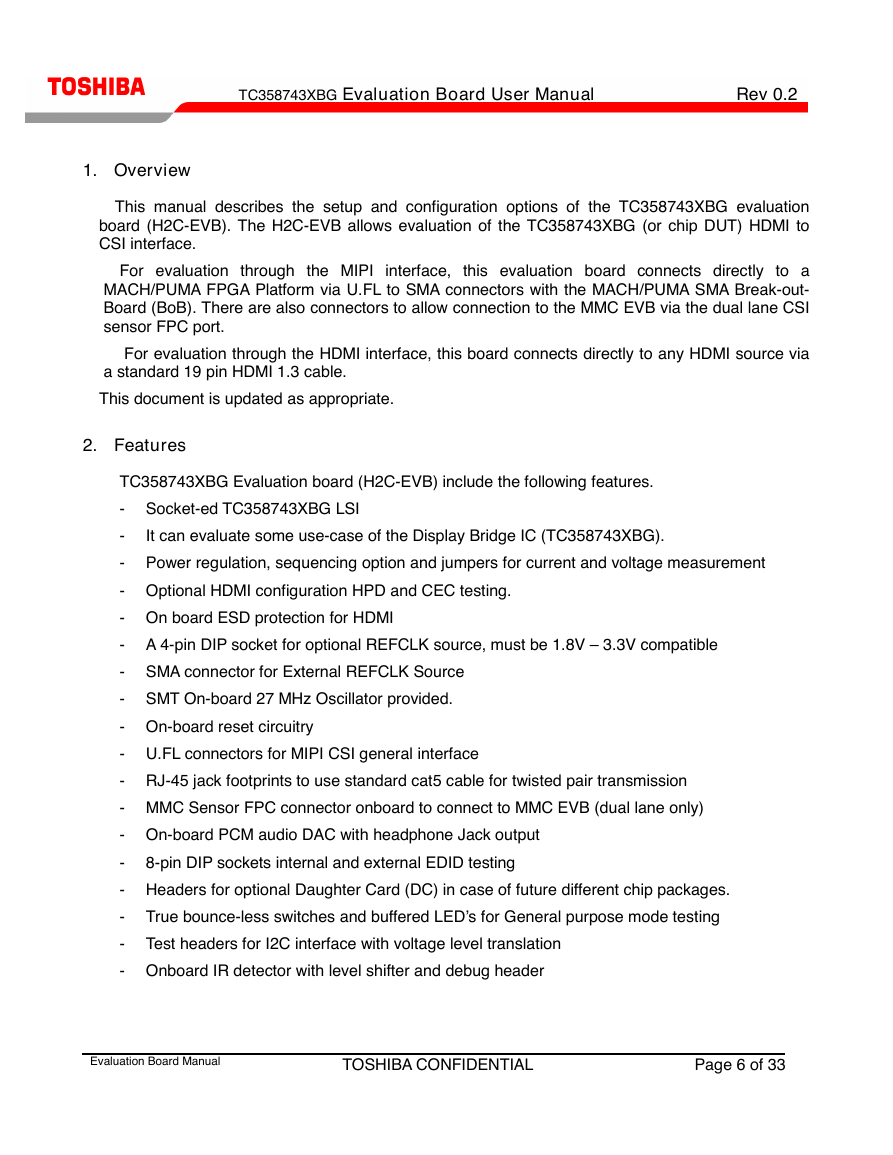
It can evaluate some use-case of the Display Bridge IC (TC358743XBG).
TC358743XBG Evaluation board (H2C-EVB) include the following features.
- Socket-ed TC358743XBG LSI
-
- Power regulation, sequencing option and jumpers for current and voltage measurement
- Optional HDMI configuration HPD and CEC testing.
- On board ESD protection for HDMI
- A 4-pin DIP socket for optional REFCLK source, must be 1.8V – 3.3V compatible
- SMA connector for External REFCLK Source
- SMT On-board 27 MHz Oscillator provided.
- On-board reset circuitry
- U.FL connectors for MIPI CSI general interface
- RJ-45 jack footprints to use standard cat5 cable for twisted pair transmission
- MMC Sensor FPC connector onboard to connect to MMC EVB (dual lane only)
- On-board PCM audio DAC with headphone Jack output
- 8-pin DIP sockets internal and external EDID testing
- Headers for optional Daughter Card (DC) in case of future different chip packages.
- True bounce-less switches and buffered LED’s for General purpose mode testing
- Test headers for I2C interface with voltage level translation
- Onboard IR detector with level shifter and debug header
Evaluation Board Manual
TOSHIBA CONFIDENTIAL
Page 6 of 33
�
TC358743XBG Evaluation Board User Manual Rev 0.2
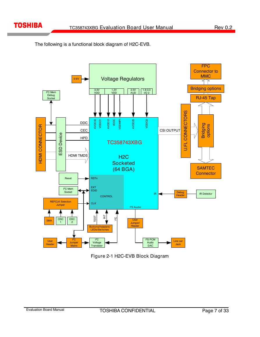
The following is a functional block diagram of H2C-EVB.
5-6V
Voltage Regulators
3.3V
VDD
1.2V
VDD
2.5V
AUD
1.8-3.3
I/O 2
I2C Mem
Debug
Socket
FPC
Connector to
MMC
Bridging options
RJ-45 Tap
DDC
CEC
HPD
HDMI TMDS
i
e
c
v
e
D
D
S
E
R
O
T
C
E
N
N
O
C
I
M
D
H
3
3
D
D
V
A
I
1
O
D
D
V
C
D
D
V
2
1
D
D
V
A
I
I
P
M
D
D
V
5
2
D
D
V
A
I
2
O
D
D
V
CSI OUTPUT
TC358743XBG
H2C
Socketed
(64 BGA)
S
R
O
T
C
E
N
N
O
C
L
F
U
.
i
g
n
g
d
i
r
B
s
n
o
i
t
p
o
SAMTEC
Connector
IR
Debug
Header
IR Detector
Reset
I2C Mem
Socket
REFCLK Selection
Jumper
SMA
OSC
1
OSC
2
RSTn
EXT
EDID
CLK
CONTROL
T
S
E
T
T
N
I
C
2
I
Buttons/headers/
LEDs/Switches
I2S Audio
User
Jumper/
Header
User
Header
I2C
Jumper
Matrix
I2C
Voltage
Translator
I2S PCM
Audio
DAC
Line out
Jack
Figure 2-1 H2C-EVB Block Diagram
Evaluation Board Manual
TOSHIBA CONFIDENTIAL
Page 7 of 33
�
TC358743XBG Evaluation Board User Manual Rev 0.2
3. Board Layout
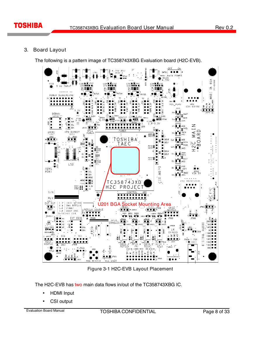
The following is a pattern image of TC358743XBG Evaluation board (H2C-EVB).
U201 BGA Socket Mounting Area
Figure 3-1 H2C-EVB Layout Placement
The H2C-EVB has two main data flows in/out of the TC358743XBG IC.
• HDMI Input
• CSI output
Evaluation Board Manual
TOSHIBA CONFIDENTIAL
Page 8 of 33
�


 2023年江西萍乡中考道德与法治真题及答案.doc
 2012年重庆南川中考生物真题及答案.doc
 2013年江西师范大学地理学综合及文艺理论基础考研真题.doc
 2020年四川甘孜小升初语文真题及答案I卷.doc
 2020年注册岩土工程师专业基础考试真题及答案.doc
 2023-2024学年福建省厦门市九年级上学期数学月考试题及答案.doc
 2021-2022学年辽宁省沈阳市大东区九年级上学期语文期末试题及答案.doc
 2022-2023学年北京东城区初三第一学期物理期末试卷及答案.doc
 2018上半年江西教师资格初中地理学科知识与教学能力真题及答案.doc
 2012年河北国家公务员申论考试真题及答案-省级.doc
 2020-2021学年江苏省扬州市江都区邵樊片九年级上学期数学第一次质量检测试题及答案.doc
 2022下半年黑龙江教师资格证中学综合素质真题及答案.doc