2009 International Conference on Networks Security, Wireless Communications and Trusted Computing
2009 International Conference on Networks Security, Wireless Communications and Trusted Computing
C-MAC: A TDMA-based MAC Protocol for Underwater Acoustic Sensor
Networks
Yutao Ma, Zhongwen Guo, Yuan Feng, Mingxing Jiang,Guanglei Feng
Department of Computer Science, Ocean university of China
{ mac863,guozhw,fengyuan, jiangmingxing,llc863}@ouc.edu.cn
Abstract
Different from terrestrial wireless networks that use
radio channel, underwater networks utilize acoustic
channel, which poses great research challenges in
medium access control (MAC) protocol design due to
its low available bandwidth and high propagation
delay characteristics. In addition, the high bit-error,
high transmission energy cost, and complex multi-path
effects in underwater environment make it even harder.
In this paper, a suitable MAC protocol, named C-MAC
(cellular MAC)
sensor
networks (UWANs) is proposed. C-MAC is a TDMA-
based MAC protocol, which divides networks into
many cells. Each cell is distributed a time slot; nodes
in a cell, can only transmit packets in the cell’s time
slot. Experiments show the protocol can avoid collision,
minimize the energy consumption, and increase the
throughput efficiency.
for underwater acoustic
1. Introduction
speaking,
[1]. Generally
efficiency of many civil
UWANs are expected to have a significant impact
and military
on the
applications
traditional
terrestrial wireless networks utilize the radio channel.
Due to the high rate of absorption of radio in the water,
we prefer acoustic in the underwater environment [2, 3].
But
the special characteristic of acoustic brings
tremendous challenges to not only the application of
UWANs but also the design of the system [4, 5, 6].
First of all,
the extremely low speed of sound in
underwater causes its propagation delay to be very high
(about 0.67msec/m). This is very high compared to
terrestrial wireless networks which are often assumed
negligible propagation delay. Secondly, it suffers from
high bit error rate and significant attenuation which
depends on frequency, so the available bandwidth is
particular limited. In addition, it is difficult to predict
978-0-7695-3610-1/09 $25.00 © 2009 IEEE
978-0-7695-3610-1/09 $25.00 © 2009 IEEE
DOI 10.1109/NSWCTC.2009.130
DOI 10.1109/NSWCTC.2009.130
728
728
the underwater environment which is changing all the
time.
inefficient.
FAMA is
Recently a lot of MAC protocols have been
proposed that attempt
to supply sufficient systems
despite the special characteristic of UWANs. PCAP
uses RTS-CTS handshake mechanism to avoid
collision [7]. PCAP allows senders to do other actions
while waiting for the CTS frame from receiver. When
the throughput of PCAP
offered load increases,
becomes
Slotted
also
handshaking based protocol which uses time slot to
avoid collision [8]. All frames can only be transmitted
at the beginning of each time slot. Nodes must be
synchronized in slotted FAMA. The long slot length
requirement reduces the throughout of the protocol. In
[9] the author proposed a distributed, energy efficient
protocol based on CSMA. It allows node to sleep in the
long propagation time, and synchronization is also
needed. Its main problem is that it assumes latency
constant. In [10] the author proposed Aloha-CA which
uses a short advance notification packet (NTF) as the
pre-engagement of dada packet. Similar with other
Aloha protocols, when offered load is very high, good
performance of protocol becomes unavailable.
2Protocol description
This dissertation is talking about a MAC protocol
based on TDMA. Time is segmented into many cycles
which are repeated continuously, and each cycle
consists of seven time slots. A time slot is made up of
data transfer phase and protection phase. The length of
protection phases is equal
to the largest expected
propagation delay in the network. Each data transfer
phase is long enough to transmit a maximum length
packet.
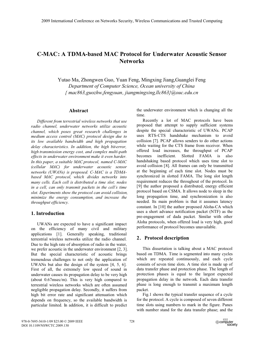
Fig.1 shows the typical transfer sequence of a cycle
for the protocol. A cycle is composed of seven different
time slots using numbers to mark in the figure. Panes
with number stand for the data transfer phase; and the
�
gray areas between each two neighboring panes are
protection phase. A data transfer phase and the
following protection phase make up of a time slot; the
numbers on panes stand for numbers of time slot. The
whole time is made up of a series of cycles, and each
cycle is a group of seven data transfer phases and seven
protection phases.
Fig.1. Sequence of the protocol
Using a TDMA-based MAC protocol
requires
nodes to maintain synchronization with their neighbors.
Because of the huge and varying acoustic propagation
delays, synchronization is very essential for a node in
order to predict when it has to send and when to
receive. We
obtain
synchronization with their neighbors through the use of
higher quality clocks and synchronization protocols. In
addition, the long time slots minimize the effect of
clock drift and synchronization inaccuracy.
assume
nodes
that
can
D 7
L
the shortest distance (using D to express) between the
the distance
nodes in same time slot. Obviously,
is
ensure
the
reliable
communication without collisions, D needs to meet
the restriction of
(where R is the communication
2!
range), so
.
RD 2!
R
In order
to
L
.
7
7
2.2 The decision of time slot
Nodes’
time slots
should be decided before
transmitting packet. Suppose that each node only
knows its own position. After being deployed, the sink
sends time decision frame which includes the position
of the sink. Nodes which receive the frame become
active nodes. Then they extract the position of the sink
from the frame, and decide their own time slots by the
relative position to the sink. Specific methods will be
introduced later. Each active node will transmit the
time decision frame in own time slot once. The process
will not stop until each node has transmitted the frame
successfully. By this way, the time slot of all nodes
could be decided quickly.
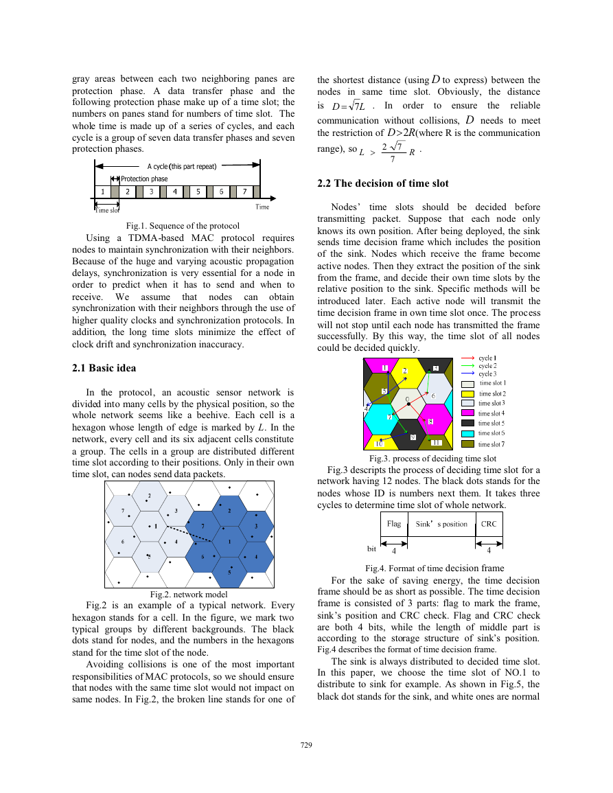
2.1 Basic idea
In the protocol, an acoustic sensor network is
divided into many cells by the physical position, so the
whole network seems like a beehive. Each cell is a
hexagon whose length of edge is marked by L. In the
network, every cell and its six adjacent cells constitute
a group. The cells in a group are distributed different
time slot according to their positions. Only in their own
time slot, can nodes send data packets.
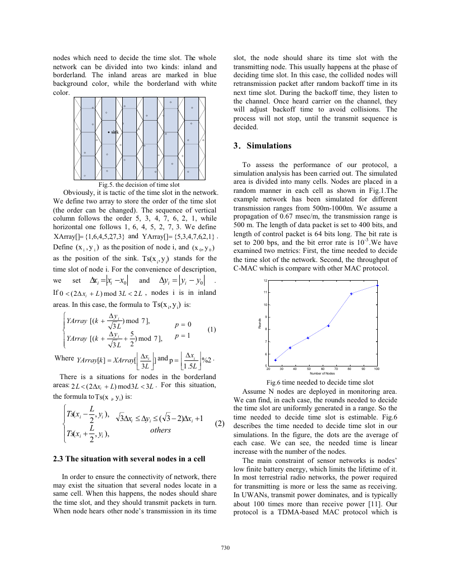
Fig.3. process of deciding time slot
Fig.3 descripts the process of deciding time slot for a
network having 12 nodes. The black dots stands for the
nodes whose ID is numbers next them. It takes three
cycles to determine time slot of whole network.
Fig.2. network model
Fig.2 is an example of a typical network. Every
hexagon stands for a cell. In the figure, we mark two
typical groups by different backgrounds. The black
dots stand for nodes, and the numbers in the hexagons
stand for the time slot of the node.
Avoiding collisions is one of the most important
responsibilities of MAC protocols, so we should ensure
that nodes with the same time slot would not impact on
same nodes. In Fig.2, the broken line stands for one of
729729
Fig.4. Format of time decision frame
For the sake of saving energy, the time decision
frame should be as short as possible. The time decision
frame is consisted of 3 parts: flag to mark the frame,
sink’s position and CRC check. Flag and CRC check
are both 4 bits, while the length of middle part is
according to the storage structure of sink’s position.
Fig.4 describes the format of time decision frame.
The sink is always distributed to decided time slot.
In this paper, we choose the time slot of NO.1 to
distribute to sink for example. As shown in Fig.5, the
black dot stands for the sink, and white ones are normal
�
nodes which need to decide the time slot. The whole
network can be divided into two kinds: inland and
borderland. The inland areas are marked in blue
background color, while the borderland with white
color.
Fig.5. the decision of time slot
and
,7,3}
{1,6,4,5,2
)y,
i
Obviously, it is tactic of the time slot in the network.
We define two array to store the order of the time slot
(the order can be changed). The sequence of vertical
column follows the order 5, 3, 4, 7, 6, 2, 1, while
horizontal one follows 1, 6, 4, 5, 2, 7, 3. We define
XArray[]
,2,1}
(x
Define
)y,
0
as the position of the sink.
stands for the
time slot of node i. For the convenience of description,
y
we
.
i
If
is in inland
0
areas. In this case, the formula to
� '
x
0x
x
i
i
�'�
L
L
3mod
as the position of node i, and
'
y
i
, nodes i
{5,3,4,7,6
(x
YArray[]
and
L
set
2(
Ts(x
Ts(x
)y,
i
0y
is:
�
xi
�
2
)
.
0
i
i
)y,
i
i
°°
®
°
°
¯
YArray
[(
k
YArray
[(
k
�
�
'
y
i
L
3
'
y
i
L
3
Where
YArray
k
][
XArray
[
)
],7mod
5
2
)
�
],7mod
p
p
0
1
(1)
« '
«¬
3
x
i
L
»
»¼
]
and
p
« '
xi
«¬
L
5.1
»
»¼
.
2%
There is a situations for nodes in the borderland
. For this situation,
�
3
L
L
L
)
)y,
i
i
3mod
is:
d'd'
x
3
i
y
)23(
�'�
1
x
i
i
others
(2)
2
L
areas:
�'�
x
2(
i
the formula to
Ts(x
yL
,
2
L
2
xTs
(
°
i
®
°
xTs
(
¯
i
y
i
�
�
,
i
),
),
2.3 The situation with several nodes in a cell
In order to ensure the connectivity of network, there
may exist the situation that several nodes locate in a
same cell. When this happens, the nodes should share
the time slot, and they should transmit packets in turn.
When node hears other node’s transmission in its time
730730
the node should share its time slot with the
slot,
transmitting node. This usually happens at the phase of
deciding time slot. In this case, the collided nodes will
retransmission packet after random backoff time in its
next time slot. During the backoff time, they listen to
the channel. Once heard carrier on the channel, they
will adjust backoff
time to avoid collisions. The
process will not stop, until the transmit sequence is
decided.
3Simulations
To assess the performance of our protocol, a
simulation analysis has been carried out. The simulated
area is divided into many cells. Nodes are placed in a
random manner in each cell as shown in Fig.1.The
example network has been simulated for different
transmission ranges from 500m-1000m. We assume a
propagation of 0.67 msec/m, the transmission range is
500 m. The length of data packet is set to 400 bits, and
length of control packet is 64 bits long. The bit rate is
set to 200 bps, and the bit error rate is 10-3.We have
examined two metrics: First, the time needed to decide
the time slot of the network. Second, the throughput of
C-MAC which is compare with other MAC protocol.
s
d
n
u
o
R
12
11
10
9
8
7
6
5
20
30
40
50
60
70
80
90
100
Number of Nodes
Fig.6 time needed to decide time slot
Assume N nodes are deployed in monitoring area.
We can find, in each case, the rounds needed to decide
the time slot are uniformly generated in a range. So the
time needed to decide time slot is estimable. Fig.6
describes the time needed to decide time slot in our
simulations. In the figure, the dots are the average of
each case. We can see,
the needed time is linear
increase with the number of the nodes.
The main constraint of sensor networks is nodes’
low finite battery energy, which limits the lifetime of it.
In most terrestrial radio networks, the power required
for transmitting is more or less the same as receiving.
In UWANs, transmit power dominates, and is typically
about 100 times more than receive power [11]. Our
protocol is a TDMA-based MAC protocol which is
�
communications,”
[1]Ian F.Akyildiz, Dario Pompili, and Tommaso Melodia.
“State of the Art
in Protocol Research for Underwater
Acoustic Sensor Networks,” WUWNet’06, pages 7-16, 2006.
[2]]M. Stojanovic, J. G. Proakis, Ed. John Wiley and Sons
“Acoustic (underwater) communications,” in Encyclopedia
of Telecommunications,2003.
[3]J.G.Proakis, E.M. Sozer, J.A.Rice, and M.Stojanovic,
“Shallow water acoustic networks,” IEEE Communications
Magazine, pp. 114–119, Nov. 2001.
[4]I.F.Akyildiz, D.Pompili, and T.Melodia, “Underwater
Acoustic Sensor Networks: Research Challenges,” Ad Hoc
Networks (Elsevier), vol. 3, no. 3, pp. 257–279, May 2005.
[5]A.B.Baggeroer, “Acoustic telemetry - An overview,”
IEEE Journal of Oceanic Engineering, vol. 9, pp. 229-235,
1984.
[6]M.Stojanovic, “Recent advances in high-speed underwater
acoustic
IEEE Journal of Oceanic
Engineering, vol. 21, no. 2, pp. 125-136, 1996.
[7]Xiaoxing Guo, Michael R. and Frater, Michael J. Ryan.
“A Propagation-delay-tolerant Collision Avoidance Protocol
for Underwater Acoustic Sensor Networks,”
In proc.
MTS/IEEE OCEANS’06, 2006.
[8]M.Molins and M.Stojanovic, “Slotted FAMA: a MAC
Protocol for Underwater Acoustic Networks,” in Proc. of
MTS/IEEE Conference
for Ocean
Engineering, Science and Technology (OCEANS), Boston,
MA, Sept. 2006.
[9]V.Rodoplu and M.K.Park. “An energy-efficient MAC
protocol for underwater wireless acoustic networks,” In Proc.
MTS/IEEE OCEANS’05. 2:1198-1203, 2005.
[10]Chirdchoo, N.Soh, and K.C.Chua. “Aloha-Based MAC
Protocols with Collision Avoidance for Underwater Acoustic
Networks,” Infocom 2007, pages 2271-2275, may 2007.
[11]J.Partan,
Practical
Issues
WUWNet, 2006.
and B.N.Levine.“A Survey of
In. Proc.
in Underwater Networks,”
and
Exhibition
J.Kurose,
inherently collision free since a set of time slots are
prearranged. And it can save energy by allowing nodes
to turn off the radio to rule out
idle listening. In
addition, our protocol dose not need control packets.
For these reasons, C-MAC saves the energy compare to
contention based protocol.
t
u
p
h
g
u
o
r
h
T
0.5
0.45
0.4
0.35
0.3
0.25
0.2
0.15
0.1
0.05
0
0
Slotted FAMA
C-MAC
0.5
1
1.5
2
2.5
3
3.5
4
4.5
5
Offered load
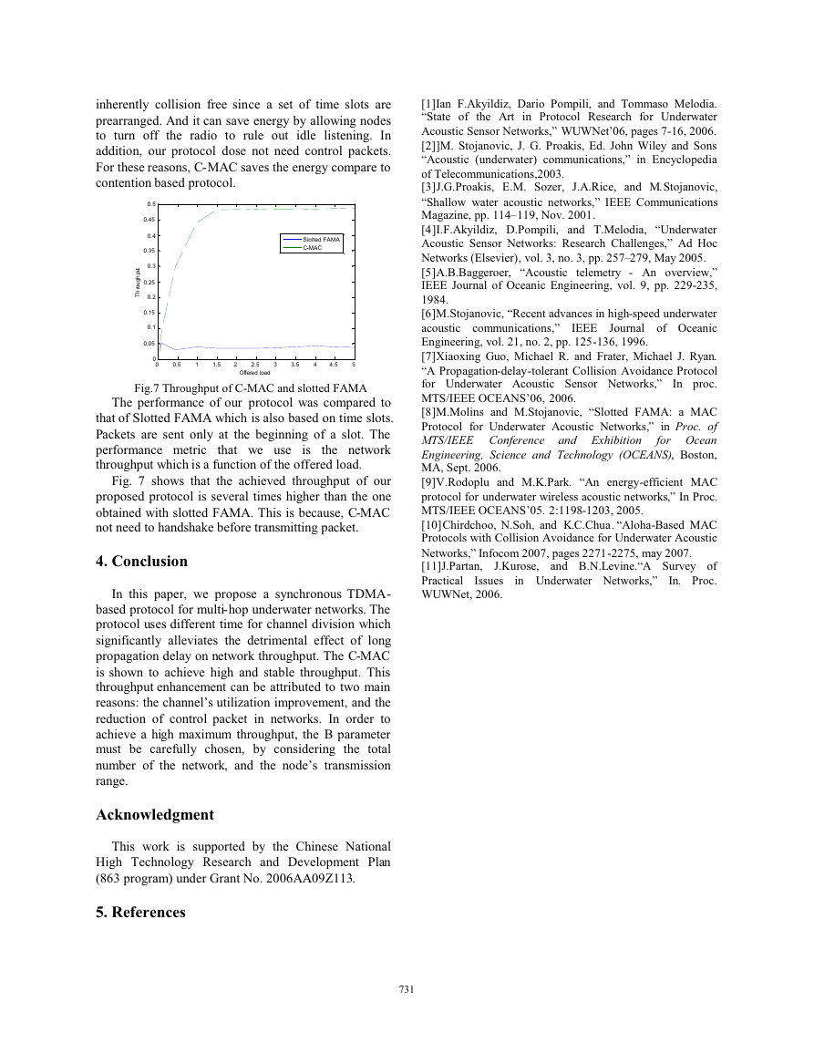
Fig.7 Throughput of C-MAC and slotted FAMA
The performance of our protocol was compared to
that of Slotted FAMA which is also based on time slots.
Packets are sent only at the beginning of a slot. The
performance metric that we use is
the network
throughput which is a function of the offered load.
Fig. 7 shows that the achieved throughput of our
proposed protocol is several times higher than the one
obtained with slotted FAMA. This is because, C-MAC
not need to handshake before transmitting packet.
4. Conclusion
In this paper, we propose a synchronous TDMA-
based protocol for multi-hop underwater networks. The
protocol uses different time for channel division which
significantly alleviates the detrimental effect of long
propagation delay on network throughput. The C-MAC
is shown to achieve high and stable throughput. This
throughput enhancement can be attributed to two main
reasons: the channel’s utilization improvement, and the
reduction of control packet in networks. In order to
achieve a high maximum throughput, the B parameter
must be carefully chosen, by considering the total
number of the network, and the node’s transmission
range.
Acknowledgment
This work is supported by the Chinese National
High Technology Research and Development Plan
(863 program) under Grant No. 2006AA09Z113.
5. References
731731
�


 2023年江西萍乡中考道德与法治真题及答案.doc
 2012年重庆南川中考生物真题及答案.doc
 2013年江西师范大学地理学综合及文艺理论基础考研真题.doc
 2020年四川甘孜小升初语文真题及答案I卷.doc
 2020年注册岩土工程师专业基础考试真题及答案.doc
 2023-2024学年福建省厦门市九年级上学期数学月考试题及答案.doc
 2021-2022学年辽宁省沈阳市大东区九年级上学期语文期末试题及答案.doc
 2022-2023学年北京东城区初三第一学期物理期末试卷及答案.doc
 2018上半年江西教师资格初中地理学科知识与教学能力真题及答案.doc
 2012年河北国家公务员申论考试真题及答案-省级.doc
 2020-2021学年江苏省扬州市江都区邵樊片九年级上学期数学第一次质量检测试题及答案.doc
 2022下半年黑龙江教师资格证中学综合素质真题及答案.doc