Chapter 1. Document Overview
1.1 Specification Objective
1.2 Terms and Acronyms
1.3 Reference Documents
Chapter 2. CCIX Overview
2.1 Introduction
2.2 Topologies
2.3 CCIX Architecture Model
2.3.1 Components of the CCIX Architecture
2.3.2 Port Aggregation
2.3.3 CCIX Extended Data Rate Physical Layer
2.4 CCIX Management Framework
2.5 RAS Architecture
2.6 Address Translation Service
2.7 Signaling Hosts from Accelerators
2.8 Establishing Trust with a CCIX Accelerator
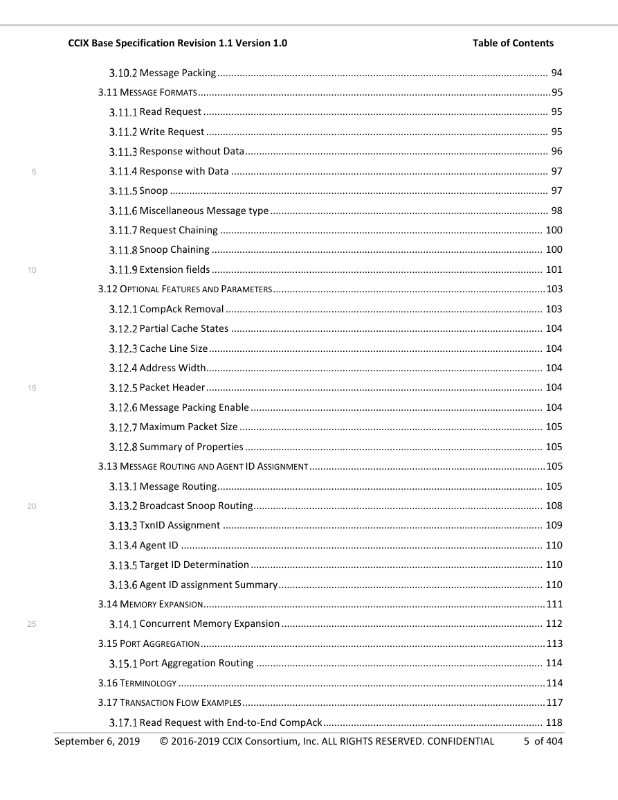
Chapter 3. Protocol Layer
3.1 Introduction
3.1.1 CCIX Agents
3.1.2 Discovery and Enumeration
3.1.3 Topologies
3.1.3.1 Fully Connected
3.1.3.2 Tree
3.1.3.3 Multi-Dimensional Array
3.2 Message Fields
3.2.1 Request Message
3.2.2 Snoop Message
3.2.3 Response Message
3.2.4 Field Descriptions
3.3 Coherence protocol
3.3.1 Cache States
3.3.2 Request Types
3.3.2.1 Read Transactions
3.3.2.2 Dataless Transactions
3.3.2.3 Write Transactions
3.3.2.4 Atomic Transactions
3.3.2.5 ReqOp Encoding
3.3.3 Request Responses
3.3.3.1 ReqRespOp Encoding
3.3.4 Snoop Requests
3.3.4.1 Snoop Data Return
3.3.4.2 SnpOp Encoding
3.3.5 Snoop Responses
3.3.5.1 SnpRespOp encoding
3.3.5.2 Snoop Response for Unique Clean and Unique Dirty states
3.3.6 MiscOp Encoding
3.3.7 Protocol Error Report
3.3.8 Request Cache State Transitions
3.3.9 State Transitions at Snoopee
3.3.10 Silent Cache State Transitions
3.3.11 Controlling the use of Evict and WriteEvictFull transactions
3.3.12 Simultaneous Outstanding Requests
3.3.13 Request to Snoop Hazard
3.3.13.1 At the Port Interface Labeled CCIX-R
3.3.13.2 At the Port Interface labeled CCIX-H
3.3.13.3 WriteBackPtlUD Request Hazard
3.4 Transaction Structure
3.4.1 Request Transactions
3.4.1.1 Fully Coherent Read Transactions
3.4.1.2 Non-coherent and IO Coherent Read Transactions
3.4.1.3 Dataless Transactions without CompAck
3.4.1.4 Dataless Transactions with CompAck
3.4.1.5 Write Transactions
3.4.1.6 Atomic Transactions
3.4.2 Snoop Transactions
3.4.2.1 Snoop without Data response
3.4.2.2 Snoop with Data Response
3.4.2.3 Misc Transactions
3.5 Address, Control, and Data
3.5.1 Address and Data Alignment
3.5.2 Request Attributes
3.5.2.1 Device
3.5.2.2 Normal Memory
3.5.3 Permitted Memory Type for Requests
3.5.4 Data and Byte Enables
3.5.4.1 Data Fields
3.5.4.2 Normal Memory
3.5.4.3 Device
3.5.4.4 Data Location Examples
3.5.4.5 Byte Enables
3.6 Ordering
3.6.1 Multi-copy Atomicity
3.6.2 Completion Response and Ordering
3.6.3 CompAck
3.6.4 Comp and Outstanding CompAck Dependency
3.7 Flow control and protocol credits
3.7.1 Protocol Credits
3.7.2 Credit Exchange
3.7.2.1 Independent Credit Exchange
3.7.2.2 Packet Header Credit Grant
3.7.2.3 Credit Exchange Rules
3.7.2.4 Agent IDs in Credit Exchange Messages
3.8 Miscellaneous Messages
3.8.1 Uncredited Misc Messages
3.8.2 Credited Misc Messages
3.8.3 ID Namespace
3.8.4 Extension Fields in Misc Message
3.9 Error Handling
3.9.1 Error Classification
3.10 Packet Header
3.10.1 Packet Header
3.10.1.1 PCIe Compatible Header
3.10.1.2 Optimized Header
3.10.1.3 Packet Header Length field
3.10.2 Message Packing
3.10.2.1 Message Packing Enable
3.10.2.2 Maximum Packet Size
3.10.2.3 Combining Properties for Multiple Interfaces
3.11 Message Formats
3.11.1 Read Request
3.11.2 Write Request
3.11.3 Response without Data
3.11.4 Response with Data
3.11.5 Snoop
3.11.6 Miscellaneous Message type
3.11.6.1 Credited Misc message
3.11.6.2 Uncredited Misc message
3.11.6.3 Credit Exchange
3.11.6.4 NOP Message
3.11.6.5 PER Message
3.11.7 Request Chaining
3.11.8 Snoop Chaining
3.11.9 Extension fields
3.11.9.1 Extension Type 0 – Additional Information
3.12 Optional Features and Parameters
3.12.1 CompAck Removal
3.12.2 Partial Cache States
3.12.3 Cache Line Size
3.12.4 Address Width
3.12.5 Packet Header
3.12.6 Message Packing Enable
3.12.7 Maximum Packet Size
3.12.8 Summary of Properties
3.13 Message Routing and Agent ID Assignment
3.13.1 Message Routing
3.13.1.1 Address Routed Messages
3.13.1.2 TgtID Assignment
3.13.1.3 ID Routed Messages
3.13.2 Broadcast Snoop Routing
3.13.2.1 Broadcast Snoop Forwarding
3.13.3 TxnID Assignment
3.13.4 Agent ID
3.13.5 Target ID Determination
3.13.6 Agent ID assignment Summary
3.14 Memory Expansion
3.14.1 Concurrent Memory Expansion
3.15 Port Aggregation
3.15.1 Port Aggregation Routing
3.16 Terminology
3.17 Transaction Flow Examples
3.17.1 Read Request with End-to-End CompAck
3.17.2 Read Request with an Early CompAck
3.17.3 Write Request
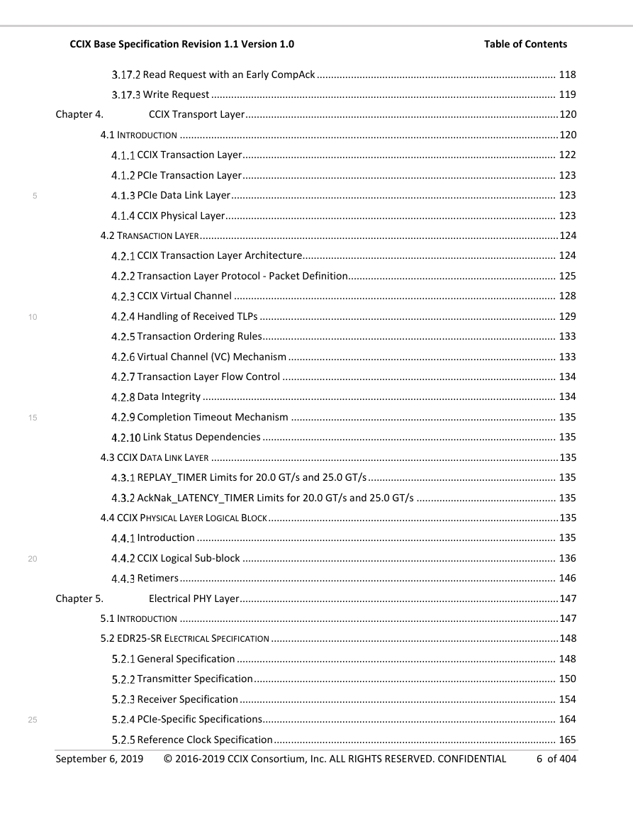
Chapter 4. CCIX Transport Layer
4.1 Introduction
4.1.1 CCIX Transaction Layer
4.1.2 PCIe Transaction Layer
4.1.3 PCIe Data Link Layer
4.1.4 CCIX Physical Layer
4.2 Transaction Layer
4.2.1 CCIX Transaction Layer Architecture
4.2.2 Transaction Layer Protocol - Packet Definition
4.2.2.1 CCIX Transaction Layer Packets
4.2.2.1.1 PCIe Compatible TLP Format
4.2.2.1.2 Optimized TLP format
4.2.2.2 Support for Multiple Protocol Messages in one CCIX TLP
4.2.2.3 Use of PCIe Compatible or Optimized TLP formats
4.2.3 CCIX Virtual Channel
4.2.4 Handling of Received TLPs
4.2.5 Transaction Ordering Rules
4.2.6 Virtual Channel (VC) Mechanism
4.2.7 Transaction Layer Flow Control
4.2.8 Data Integrity
4.2.9 Completion Timeout Mechanism
4.2.10 Link Status Dependencies
4.3 CCIX Data Link Layer
4.3.1 REPLAY_TIMER Limits for 20.0 GT/s and 25.0 GT/s
4.3.2 AckNak_LATENCY_TIMER Limits for 20.0 GT/s and 25.0 GT/s
4.4 CCIX Physical Layer Logical Block
4.4.1 Introduction
4.4.2 CCIX Logical Sub-block
4.4.2.1 CCIX Extended Speed Mode (ESM)
4.4.2.2 CCIX PHY Types
4.4.2.3 ESM Operation
4.4.2.3.1 ESM Operational Mechanisms
4.4.2.3.2 ESM Operation Example
4.4.2.3.2.1 Initial Link-Up to 25.0 GT/s ESM Operation
4.4.3 Retimers
Chapter 5. Electrical PHY Layer
5.1 Introduction
5.2 EDR25-SR Electrical Specification
5.2.1 General Specification
5.2.1.1 Line Rate
5.2.1.2 Line Coding
5.2.1.3 Crosstalk
5.2.1.4 Baud Rate Tolerance
5.2.1.5 AC Coupling Capacitor
5.2.1.6 Target Bit Error Rate
5.2.1.7 Reference Model
5.2.2 Transmitter Specification
5.2.2.1 Driver Termination
5.2.2.2 Differential Return Loss of Transmitter
5.2.2.3 Common Mode Output Return Loss
5.2.2.4 Transmitter PLL Bandwidth and Peaking
5.2.2.5 TX Voltage Parameters
5.2.2.5.1 Signal Definition
5.2.2.5.2 Transmitter AC Specification
5.2.2.5.3 Transmitter Equalization
5.2.2.5.4 TX Equalization Presets
5.2.2.5.5 Measuring Presets at EDR25-SR PHY
5.2.2.5.6 EIEOS and VTX-EIEOS-FS and VTX-EIEOS-RS Limit
5.2.2.6 TX Timing Parameters
5.2.2.6.1 Jitter Parameters
5.2.2.6.2 De-Embedding the Breakout Channel for TX Jitter Measurement
5.2.2.6.3 Behavioral CDR Characteristics
5.2.3 Receiver Specification
5.2.3.1 Receiver Termination
5.2.3.2 Differential Return Loss of Receiver
5.2.3.3 Common Return Loss of Receiver
5.2.3.4 Common Receiver Parameters
5.2.3.5 Jitter Tolerance
5.2.3.6 Receiver Stressed Eye Specification
5.2.3.6.1 Breakout and Replica Channels
5.2.3.6.2 Calibration Channel Insertion Loss Characteristics
5.2.3.6.3 Post Processing Procedures
5.2.3.6.4 Behavioral Rx Package Models
5.2.3.6.5 Behavioral CDR Model
5.2.3.6.6 Behavioral CTLE
5.2.3.6.7 Behavioral DFE
5.2.3.7 Calibration Stress Eye for Jitter Tolerance
5.2.3.7.1 Procedure to Calibrate Stressed Eye
5.2.3.7.2 Procedure for Testing Rx DUT
5.2.3.7.3 Waveform Post Processing Tool Requirements
5.2.3.8 Receiver Refclk Modes
5.2.4 PCIe-Specific Specifications
5.2.4.1 Electrical Idle
5.2.4.2 Receiver Detection
5.2.4.3 Receiver Margining
5.2.4.4 Link Training for TX EQ with Back Channel
5.2.5 Reference Clock Specification
5.2.5.1 Reference Clock Electrical Specification
5.2.5.2 Reference Clock Compliance Measurement
5.2.5.3 CDR and PLL Bandwidth and Peaking for Reference Clock Compliance
5.2.6 Channel Compliance
5.2.6.1 Channel Compliance Methodology
5.2.6.1.1 Using Internal EW/EH with reference receiver
5.2.6.1.2 Behavioral CTLE
5.2.6.1.3 Behavioral Transmitter and Receiver Package Models (Informative)
5.2.6.1.4 Behavior Transmitter Parameters
5.2.6.2 Frequency Domain Response for Channel Compliance (Informative)
5.2.6.2.1 Insertion Loss Between Reference Point Tdie and Rdie (Informative)
5.2.6.2.2 Differential Return Loss of Channel (Informative)
5.2.6.2.3 Insertion Loss Deviation (Informative)
5.2.6.2.4 Integrated Crosstalk Noise (Informative)
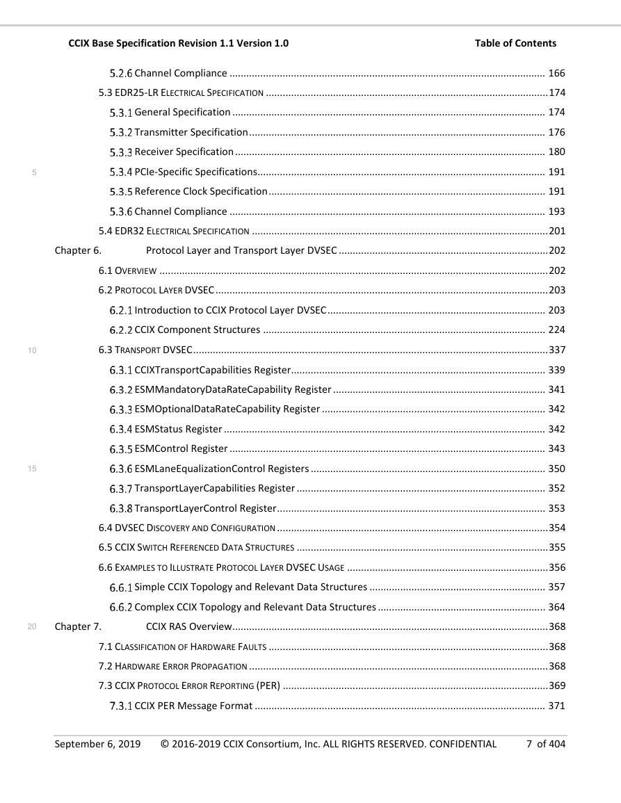
5.3 EDR25-LR Electrical Specification
5.3.1 General Specification
5.3.1.1 Line Rate
5.3.1.2 Line Coding
5.3.1.3 Crosstalk
5.3.1.4 Baud Rate Tolerance
5.3.1.5 AC Coupling Capacitor
5.3.1.6 Target Bit Error Rate
5.3.1.7 Reference Model
5.3.2 Transmitter Specification
5.3.2.1 Driver Termination
5.3.2.2 Differential Return Loss of Transmitter
5.3.2.3 Common Mode Output Return Loss
5.3.2.4 Transmitter PLL Bandwidth and Peaking
5.3.2.5 TX Voltage Parameters
5.3.2.5.1 Signal Definition
5.3.2.5.2 Transmitter AC Specification
5.3.2.5.3 Transmitter Equalization
5.3.2.5.4 TX Equalization Presets
5.3.2.5.5 Measuring Presets at EDR25-LR PHY
5.3.2.5.6 EIEOS and VTX-EIEOS-FS and VTX-EIEOS-RS Limit
5.3.2.6 TX Timing Parameters
5.3.2.6.1 Jitter Parameters
5.3.2.6.2 De-Embedding the Breakout Channel for TX Jitter Measurement
5.3.2.6.3 Behavioral CDR Characteristics
5.3.3 Receiver Specification
5.3.3.1 Receiver Termination
5.3.3.2 Differential Return Loss of Receiver
5.3.3.3 Common Return Loss of Receiver
5.3.3.4 Common Receiver Parameters
5.3.3.5 Jitter Tolerance
5.3.3.6 Receiver Stressed Eye Specification
5.3.3.6.1 Breakout and Replica Channels
5.3.3.6.2 Calibration Channel Insertion Loss Characteristics
5.3.3.6.3 Post Processing Procedures
5.3.3.6.4 Behavioral Rx Package Models
5.3.3.6.5 Behavioral CDR Model
5.3.3.6.6 Behavioral CTLE
5.3.3.6.7 Behavioral DFE
5.3.3.7 Calibration Stress Eye for Jitter Tolerance
5.3.3.7.1 Procedure to Calibrate Stressed Eye
5.3.3.7.2 Procedure for Testing Rx DUT
5.3.3.7.3 Waveform Post Processing Tool Requirements
5.3.3.8 Receiver Refclk Modes
5.3.4 PCIe-Specific Specifications
5.3.4.1 Electrical Idle
5.3.4.2 Receiver Detection
5.3.4.3 Receiver Margining
5.3.4.4 Link Training for TX EQ with back channel
5.3.5 Reference Clock Specification
5.3.5.1 Reference Clock Electrical Specification
5.3.5.2 Reference Clock Compliance measurement
5.3.5.3 CDR and PLL Bandwidth and Peaking for Reference Clock Compliance
5.3.6 Channel Compliance
5.3.6.1 Channel Compliance Methodology
5.3.6.1.1 Using Internal EW/EH with reference receiver
5.3.6.1.2 Behavioral CTLE
5.3.6.1.3 Behavioral Transmitter and Receiver Package Models For LR (Informative)
5.3.6.1.4 Behavior Transmitter Parameters
5.3.6.2 Frequency Domain Response for Channel Compliance (Informative)
5.3.6.2.1 Insertion Loss between reference point Tdie and Rdie (Informative)
5.3.6.2.2 Differential Return Loss of Channel (Informative)
5.3.6.2.3 Insertion Loss Deviation (Informative)
5.3.6.2.4 Integrated Crosstalk Noise (Informative)
5.4 EDR32 Electrical Specification
Chapter 6. Protocol Layer and Transport Layer DVSEC
6.1 Overview
6.2 Protocol Layer DVSEC
6.2.1 Introduction to CCIX Protocol Layer DVSEC
6.2.1.1 Location of CCIX Protocol Layer DVSEC
6.2.1.2 PCIe Function Level Reset (FLR)
6.2.1.3 PCIe ARI and SR-IOV
6.2.1.4 CCIX Protocol Layer DVSEC Header
6.2.1.5 Sequence for Capabilities & Status and Control Structures
6.2.1.5.1 Sequence for Multiport CCIX Devices
6.2.1.6 Capabilities & Status Structure and Control Structure
6.2.1.7 Version Numbers and their impact on data structure definition
6.2.1.8 CCIX Topology creation via Address Space and CCIX AgentID name space allocation
6.2.1.8.1 Global ID Map (G-IDM)
6.2.1.8.2 Global RA-to-HA System Address Map (G-RSAM)
6.2.1.8.3 Global HA-to-SA System Address Map (G-HSAM)
6.2.1.8.4 CCIX Device view of G-IDM, G-RSAM, and G-HSAM
6.2.1.9 CCIX Component Address and ID based routing tables
6.2.2 CCIX Component Structures
6.2.2.1 Common Structures
6.2.2.1.1 Common Capabilities & Status Data Structures
6.2.2.1.2 Common Control Data Structures
6.2.2.1.2.1 Snoop Request Hash Mask
6.2.2.1.2.2 CCIX Software Services Portal
6.2.2.2 IDM Table Structure
6.2.2.2.1 IDM Table Usage by CCIX Components
6.2.2.2.2 Routing of Responses for CCIX AgentIDs with CCIX Port Aggregation
6.2.2.2.3 Routing of Snoop Requests for CCIX Devices with CCIX Port Aggregation
6.2.2.2.4 Routing of Snoop Responses for CCIX Devices that support Mesh Topologies
6.2.2.3 SAM Table Structure
6.2.2.3.1 Common SAM Entry
6.2.2.3.2 Hash Mask
6.2.2.3.3 Aggregated Port Selection Function
6.2.2.3.4 SAM Table Usage and Restrictions for CCIX Components
6.2.2.4 Memory Pool and BAT Structures
6.2.2.4.1 Memory Pool Capabilities & Status Structure
6.2.2.4.2 BAT Control Structure
6.2.2.4.2.1 BAT Base Address Type Control Entry
6.2.2.4.2.2 BAT Fixed Offset Type Control Entry
6.2.2.4.3 Relation between HA Memory Pool Structures and HBAT Entry Structures
6.2.2.5 CCIX Port Structures
6.2.2.5.1 CCIX Port Capabilities & Status Register
6.2.2.5.2 CCIX Port Control Register
6.2.2.5.3 PSAM Entry
6.2.2.6 CCIX Link Structures
6.2.2.6.1 CCIX Link Capabilities & Status Structure
6.2.2.6.2 CCIX Link Control Structure
6.2.2.6.2.1 CCIX Link Attribute Control Structure
6.2.2.6.2.1.1 Broadcast Forward Control Vector
6.2.2.6.2.2 CCIX Link TransportID Map Entry
6.2.2.7 Home Agent Structures
6.2.2.7.1 Home Agent Capabilities & Status Structure
6.2.2.7.2 Home Agent Control Structure
6.2.2.8 Request Agent Structures
6.2.2.8.1 Request Agent Capabilities & Status Structure
6.2.2.8.2 Request Agent Control Structure
6.2.2.9 Slave Agent Structures
6.2.2.9.1 Slave Agent Capabilities & Status Structure
6.2.2.9.2 Slave Agent Control Structure
6.2.2.10 AF Properties Stuctures
6.2.2.10.1 AF Properties Capabilities & Status Structure
6.2.2.10.1.1 RA Reference Index Structure
6.2.2.10.1.2 AF Reference Index Structure
6.2.2.10.1.3 AF to RA Binding Capability Structure
6.2.2.10.2 AF to RA Properties Control Structure
6.2.2.10.2.1 AF to RA Binding Control Entries
6.3 Transport DVSEC
6.3.1 CCIXTransportCapabilities Register
6.3.2 ESMMandatoryDataRateCapability Register
6.3.3 ESMOptionalDataRateCapability Register
6.3.4 ESMStatus Register
6.3.5 ESMControl Register
6.3.5.1 Rules for Programming ESM Fields
6.3.6 ESMLaneEqualizationControl Registers
6.3.7 TransportLayerCapabilities Register
6.3.8 TransportLayerControl Register
6.4 DVSEC Discovery and Configuration
6.5 CCIX Switch Referenced Data Structures
6.6 Examples to Illustrate Protocol Layer DVSEC Usage
6.6.1 Simple CCIX Topology and Relevant Data Structures
6.6.1.1 Simple CCIX Topology and Associated SAM and BAT Data Structures
6.6.2 Complex CCIX Topology and Relevant Data Structures
6.6.2.1 Complex Topology and Associated Number of SAM Entries
Chapter 7. CCIX RAS Overview
7.1 Classification of Hardware Faults
7.2 Hardware Error Propagation
7.3 CCIX Protocol Error Reporting (PER)
7.3.1 CCIX PER Message Format
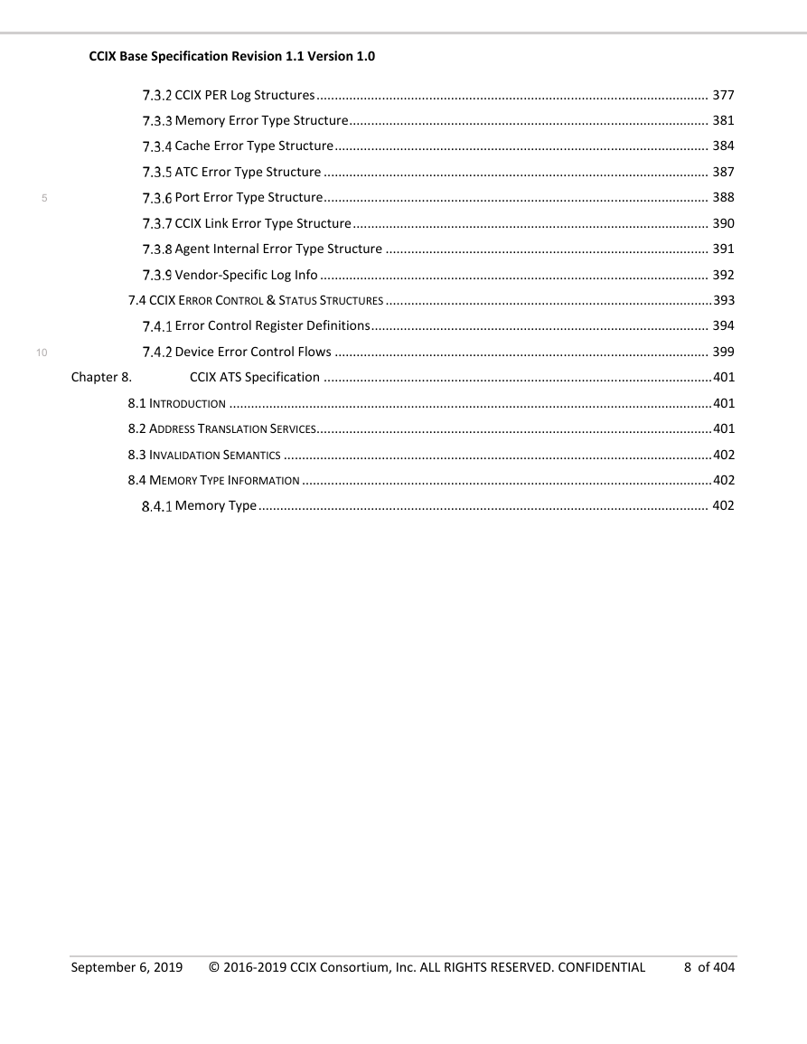
7.3.2 CCIX PER Log Structures
7.3.2.1 CCIX PER Log Header
7.3.2.2 Overwrite / Overflow Rules in Multiple Error Scenarios
7.3.3 Memory Error Type Structure
7.3.4 Cache Error Type Structure
7.3.5 ATC Error Type Structure
7.3.6 Port Error Type Structure
7.3.7 CCIX Link Error Type Structure
7.3.8 Agent Internal Error Type Structure
7.3.9 Vendor-Specific Log Info
7.4 CCIX Error Control & Status Structures
7.4.1 Error Control Register Definitions
7.4.2 Device Error Control Flows
7.4.2.1 Error Masking Rules
7.4.2.2 Recommended Flow for Enabling Errors at Boot
7.4.2.3 Guidelines for Dynamic Error Mask Updates
Chapter 8. CCIX ATS Specification
8.1 Introduction
8.2 Address Translation Services
8.3 Invalidation Semantics
8.4 Memory Type Information
8.4.1 Memory Type


 2023年江西萍乡中考道德与法治真题及答案.doc
 2012年重庆南川中考生物真题及答案.doc
 2013年江西师范大学地理学综合及文艺理论基础考研真题.doc
 2020年四川甘孜小升初语文真题及答案I卷.doc
 2020年注册岩土工程师专业基础考试真题及答案.doc
 2023-2024学年福建省厦门市九年级上学期数学月考试题及答案.doc
 2021-2022学年辽宁省沈阳市大东区九年级上学期语文期末试题及答案.doc
 2022-2023学年北京东城区初三第一学期物理期末试卷及答案.doc
 2018上半年江西教师资格初中地理学科知识与教学能力真题及答案.doc
 2012年河北国家公务员申论考试真题及答案-省级.doc
 2020-2021学年江苏省扬州市江都区邵樊片九年级上学期数学第一次质量检测试题及答案.doc
 2022下半年黑龙江教师资格证中学综合素质真题及答案.doc