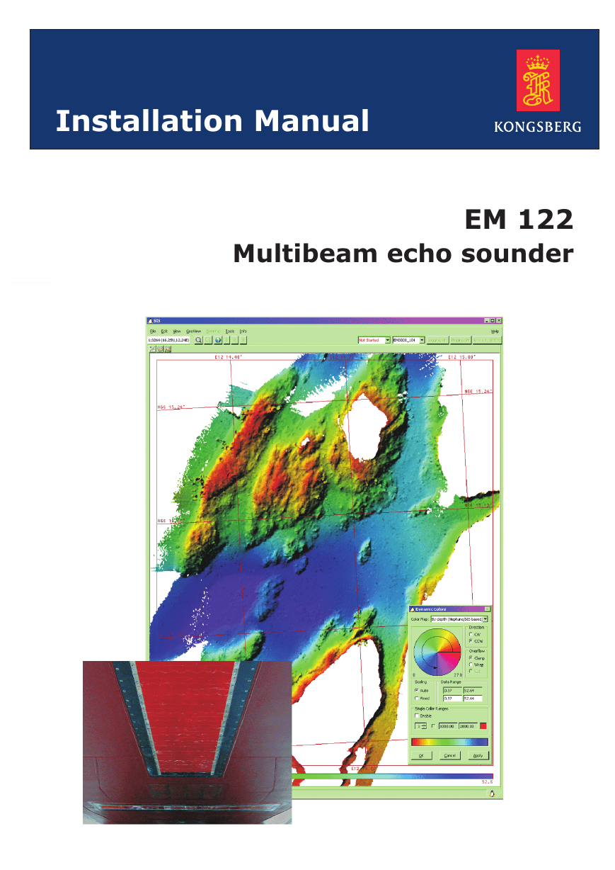
Installation Manual
EM 122
Multibeam echo sounder
�
�
EM 122
Installation Manual
This manual provides you with the basic information
required to install the EM 122 Multibeam echo sounder
system.
For more detailed information about the practical use of
the product, refer to the EM 122 Multibeam echo sounder
Operator manual.
317669/A
May 2008
�
Document history
Document number: 317669
Rev. A
May 2008
First version.
Copyright
©2008 Kongsberg Maritime AS
The information contained in this document remains the sole property of Kongsberg Maritime AS. No part
of this document may be copied or reproduced in any form or by any means, and the information contained
within it is not to be communicated to a third party, without the prior written consent of Kongsberg
Maritime AS. The document, or any part of it, may not be translated to any other language without the
written approval from Kongsberg Maritime AS.
Disclaimer
Kongsberg Maritime AS endeavours to ensure that all information in this document is correct and fairly
stated, but does not accept liability for any errors or omissions.
Warning
The equipment to which this manual applies must only be used for the purpose for which it was
designed. Improper use or maintenance may cause damage to the equipment and/or injury to personnel.
The user must be familiar with the contents of the appropriate manuals before attempting to install,
operate or work on the equipment.
Kongsberg Maritime AS disclaims any responsibility for damage or injury caused by improper
installation, use or maintenance of the equipment.
Support
If you require maintenance on your equipment, contact Kongsberg Maritime AS using the following
address:km.hydrographic.support@kongsberg.com. If you need other information about this product, or
any other Kongsberg Maritime AS products, visit http://www.km.kongsberg.com.
Kongsberg Maritime AS
Strandpromenaden 50
P.O.Box 111
N-3191 Horten,
Norway
Telephone: +47 33 02 38 00
Telefax: +47 33 04 47 53
www.kongsberg.com
subsea@kongsberg.com
�
Installation Manual
Table of contents
2.2
2.3
2.4
3
3.1
1
ABOUT THIS MANUAL ....................................................... 9
2
EM 122............................................................................ 10
2.1 Brief system description.........................................................................................10
Transducer arrays........................................................................................ 10
2.1.1
Transceiver Unit ......................................................................................... 11
2.1.2
Preamplifier Unit ........................................................................................ 11
2.1.3
Tx Junction Box(es).................................................................................... 11
2.1.4
Operator Station ......................................................................................... 11
2.1.5
Scope of supply ......................................................................................................13
Supply conditions...................................................................................................14
2.3.1
Equipment responsibility............................................................................. 14
Project management.................................................................................... 14
2.3.2
2.3.3
Installation, supervision and commissioning ................................................. 15
Installation requirements ........................................................................................17
2.4.1
Power supply.............................................................................................. 17
Environmental requirements........................................................................ 17
2.4.2
Noise sources ............................................................................................. 17
2.4.3
2.4.4
Dry docking ............................................................................................... 17
Wiring........................................................................................................ 18
2.4.5
2.4.6
Warranty .................................................................................................... 18
TRANSDUCER ARRAYS .................................................... 19
Installation principles .............................................................................................19
Basic description ........................................................................................ 19
3.1.1
3.1.2
Installation philosophy ................................................................................ 19
3.2 Locating the transducer array .................................................................................21
The boundary water layer ............................................................................ 21
3.2.1
Propeller noise............................................................................................ 21
3.2.2
Noise from protruding objects on the hull..................................................... 22
3.2.3
3.2.4
Summary.................................................................................................... 23
Installation steps.....................................................................................................24
Steel conduits .........................................................................................................27
Logistics and references .............................................................................. 27
3.4.1
3.4.2
Procedure................................................................................................... 27
3.5 Casings ...................................................................................................................29
Logistics and references .............................................................................. 29
Procedure................................................................................................... 29
3.6 Mounting frames ....................................................................................................29
Logistics and references .............................................................................. 30
Procedures ................................................................................................. 30
3.6.1
3.6.2
3.5.1
3.5.2
3.3
3.4
317669/A
3
�
Kongsberg EM 122
4.1.1
4.1.2
5.3
3.7 Transducer modules................................................................................................32
Logistics and references .............................................................................. 32
3.7.1
3.7.2
Procedure................................................................................................... 32
4
INSTALLATION EXAMPLES .............................................. 35
4.1 Transducer blister ...................................................................................................35
Logistics and references .............................................................................. 35
Procedure................................................................................................... 35
4.2 Gondola ..................................................................................................................36
Flush mount............................................................................................................36
4.3
4.4
Fairing ....................................................................................................................37
5
SYSTEM UNITS................................................................ 38
5.1 Operator station ......................................................................................................38
5.2 Transceiver Unit .....................................................................................................39
Location..................................................................................................... 39
5.2.1
General information.................................................................................... 41
5.2.2
Logistics .................................................................................................... 42
5.2.3
Procedure................................................................................................... 42
5.2.4
Surface preservation.................................................................................... 43
5.2.5
5.2.6
Internal connections.................................................................................... 44
Preamplifier Unit ....................................................................................................45
5.3.1
Scope......................................................................................................... 45
Location..................................................................................................... 45
5.3.2
General information.................................................................................... 45
5.3.3
5.3.4
Logistics .................................................................................................... 46
Procedures ................................................................................................. 46
5.3.5
5.4 Tx Junction Box(es) ...............................................................................................50
Location..................................................................................................... 51
Logistics .................................................................................................... 51
Procedures ................................................................................................. 51
Surface preservation.................................................................................... 52
5.5 Remote Control Junction Box ................................................................................52
Scope......................................................................................................... 52
5.5.1
Location..................................................................................................... 52
5.5.2
General information.................................................................................... 52
5.5.3
Logistics .................................................................................................... 52
5.5.4
5.5.5
Procedures ................................................................................................. 53
6
TECHNICAL SPECIFICATIONS ......................................... 55
6.1
Interfaces ................................................................................................................55
6.2
Physical specifications............................................................................................56
6.3
Power requirements................................................................................................57
6.4 Environmental and EMC specifications .................................................................58
5.4.1
5.4.2
5.4.3
5.4.4
4
317669/A
�
Installation Manual
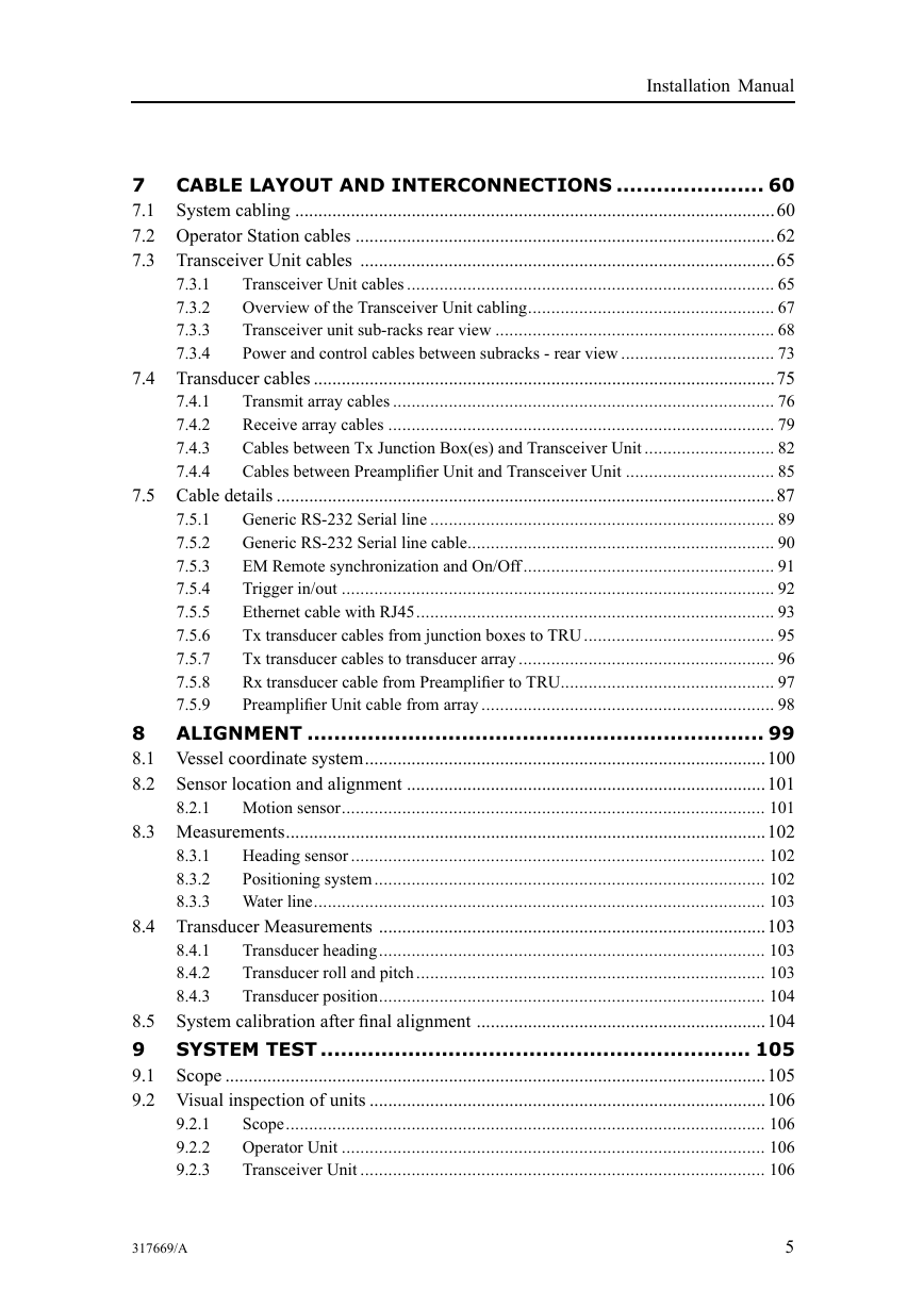
7.3.1
7.3.2
7.3.3
7.3.4
7.4.1
7.4.2
7.4.3
7.4.4
CABLE LAYOUT AND INTERCONNECTIONS ...................... 60
7
7.1
System cabling .......................................................................................................60
7.2 Operator Station cables ..........................................................................................62
7.3 Transceiver Unit cables .........................................................................................65
Transceiver Unit cables ............................................................................... 65
Overview of the Transceiver Unit cabling..................................................... 67
Transceiver unit sub-racks rear view ............................................................ 68
Power and control cables between subracks - rear view ................................. 73
7.4 Transducer cables ...................................................................................................75
Transmit array cables .................................................................................. 76
Receive array cables ................................................................................... 79
Cables between Tx Junction Box(es) and Transceiver Unit ............................ 82
Cables between Preamplifier Unit and Transceiver Unit ................................ 85
7.5 Cable details ...........................................................................................................87
Generic RS-232 Serial line .......................................................................... 89
7.5.1
Generic RS-232 Serial line cable.................................................................. 90
7.5.2
EM Remote synchronization and On/Off...................................................... 91
7.5.3
Trigger in/out ............................................................................................. 92
7.5.4
Ethernet cable with RJ45............................................................................. 93
7.5.5
Tx transducer cables from junction boxes to TRU......................................... 95
7.5.6
Tx transducer cables to transducer array ....................................................... 96
7.5.7
Rx transducer cable from Preamplifier to TRU.............................................. 97
7.5.8
7.5.9
Preamplifier Unit cable from array ............................................................... 98
ALIGNMENT .................................................................... 99
8
8.1 Vessel coordinate system......................................................................................100
Sensor location and alignment .............................................................................101
8.2
8.2.1
Motion sensor........................................................................................... 101
8.3 Measurements.......................................................................................................102
Heading sensor ......................................................................................... 102
Positioning system.................................................................................... 102
Water line................................................................................................. 103
8.4 Transducer Measurements ...................................................................................103
Transducer heading................................................................................... 103
8.4.1
Transducer roll and pitch........................................................................... 103
8.4.2
8.4.3
Transducer position................................................................................... 104
System calibration after final alignment ..............................................................104
8.5
SYSTEM TEST ................................................................ 105
9
9.1
Scope ....................................................................................................................105
9.2 Visual inspection of units .....................................................................................106
Scope....................................................................................................... 106
Operator Unit ........................................................................................... 106
Transceiver Unit ....................................................................................... 106
8.3.1
8.3.2
8.3.3
9.2.1
9.2.2
9.2.3
317669/A
5
�
Kongsberg EM 122
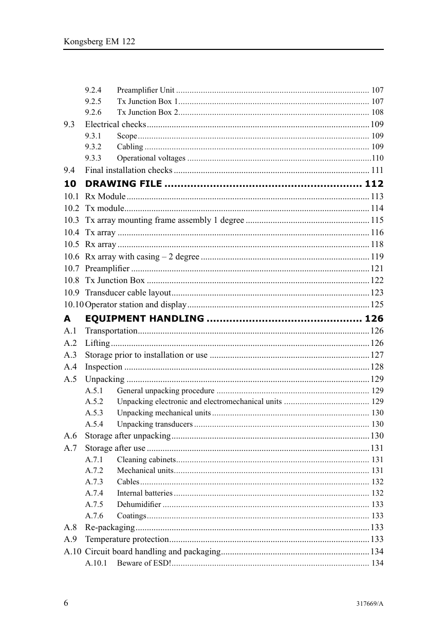
9.2.4
9.2.5
9.2.6
Preamplifier Unit ...................................................................................... 107
Tx Junction Box 1..................................................................................... 107
Tx Junction Box 2..................................................................................... 108
9.3 Electrical checks...................................................................................................109
Scope....................................................................................................... 109
9.3.1
Cabling .................................................................................................... 109
9.3.2
9.3.3
Operational voltages ..................................................................................110
Final installation checks ....................................................................................... 111
9.4
10 DRAWING FILE ............................................................. 112
10.1 Rx Module............................................................................................................ 113
10.2 Tx module............................................................................................................. 114
10.3 Tx array mounting frame assembly 1 degree ....................................................... 115
10.4 Tx array ................................................................................................................ 116
10.5 Rx array ................................................................................................................ 118
10.6 Rx array with casing – 2 degree ........................................................................... 119
10.7 Preamplifier ..........................................................................................................121
10.8 Tx Junction Box ...................................................................................................122
10.9 Transducer cable layout........................................................................................123
10.10Operator station and display.................................................................................125
A
EQUIPMENT HANDLING ................................................ 126
A.1 Transportation.......................................................................................................126
A.2 Lifting...................................................................................................................126
A.3 Storage prior to installation or use .......................................................................127
A.4 Inspection .............................................................................................................128
A.5 Unpacking ............................................................................................................129
General unpacking procedure .................................................................... 129
Unpacking electronic and electromechanical units ...................................... 129
Unpacking mechanical units ...................................................................... 130
Unpacking transducers .............................................................................. 130
A.6 Storage after unpacking........................................................................................130
A.7 Storage after use ...................................................................................................131
A.7.1
Cleaning cabinets...................................................................................... 131
A.7.2 Mechanical units....................................................................................... 131
Cables...................................................................................................... 132
A.7.3
Internal batteries ....................................................................................... 132
A.7.4
A.7.5
Dehumidifier ............................................................................................ 133
Coatings................................................................................................... 133
A.7.6
A.8 Re-packaging........................................................................................................133
A.9 Temperature protection.........................................................................................133
A.10 Circuit board handling and packaging..................................................................134
A.10.1 Beware of ESD!........................................................................................ 134
A.5.1
A.5.2
A.5.3
A.5.4
6
317669/A
�




 2023年江西萍乡中考道德与法治真题及答案.doc
 2012年重庆南川中考生物真题及答案.doc
 2013年江西师范大学地理学综合及文艺理论基础考研真题.doc
 2020年四川甘孜小升初语文真题及答案I卷.doc
 2020年注册岩土工程师专业基础考试真题及答案.doc
 2023-2024学年福建省厦门市九年级上学期数学月考试题及答案.doc
 2021-2022学年辽宁省沈阳市大东区九年级上学期语文期末试题及答案.doc
 2022-2023学年北京东城区初三第一学期物理期末试卷及答案.doc
 2018上半年江西教师资格初中地理学科知识与教学能力真题及答案.doc
 2012年河北国家公务员申论考试真题及答案-省级.doc
 2020-2021学年江苏省扬州市江都区邵樊片九年级上学期数学第一次质量检测试题及答案.doc
 2022下半年黑龙江教师资格证中学综合素质真题及答案.doc