logo资料库

通用电气变压器保护说明书(英文版).pdf

第1页 / 共568页
第2页 / 共568页
第3页 / 共568页
第4页 / 共568页
第5页 / 共568页
第6页 / 共568页
第7页 / 共568页
第8页 / 共568页
资料共568页,剩余部分请下载后查看
Title Page
Addendum
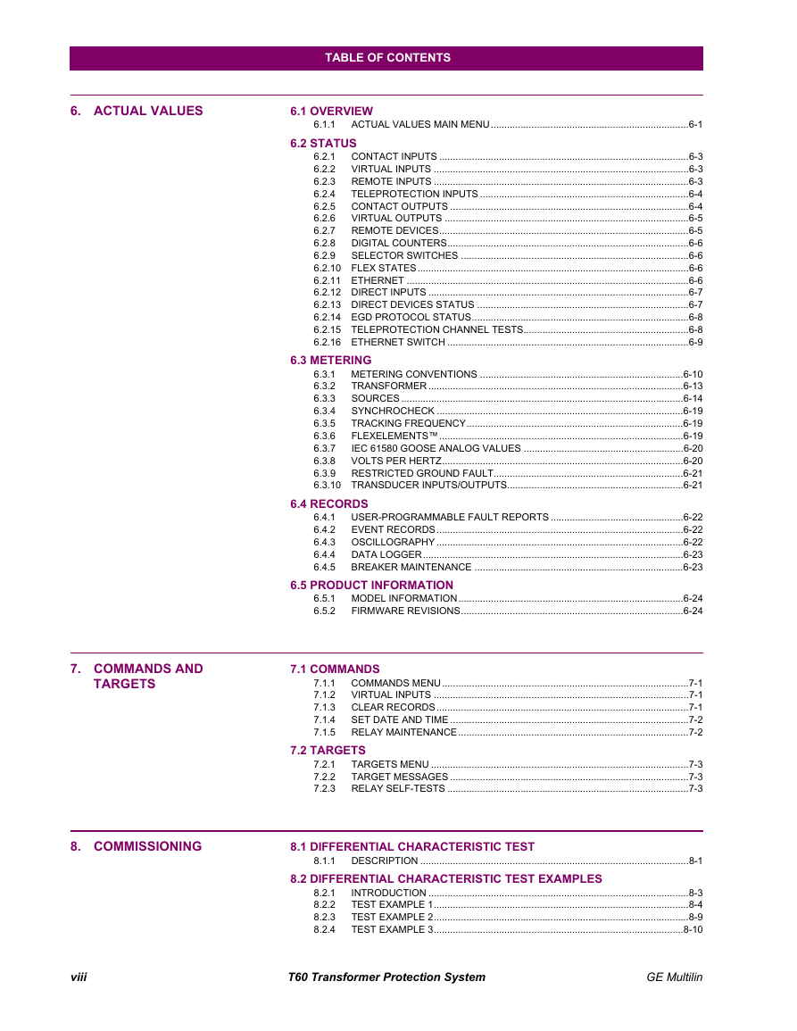
Table of Contents
Getting Started
Important Procedures
1.1.1 Cautions and Warnings
1.1.2 Inspection Checklist
UR Overview
1.2.1 Introduction to the UR
1.2.2 Hardware Architecture
a) UR Basic Design
b) UR Signal Types
c) UR Scan Operation
1.2.3 Software Architecture
1.2.4 Important Concepts
EnerVista UR Setup Software
1.3.1 PC Requirements
1.3.2 Installation
1.3.3 Configuring the T60 for Software Access
a) Overview
b) Configuring Serial Communications
c) Configuring Ethernet Communications
1.3.4 Using the Quick Connect Feature
a) Using Quick Connect via the Front Panel RS232 Port
b) Using Quick Connect via the Rear Ethernet Ports
1.3.5 Connecting to the T60 Relay
UR Hardware
1.4.1 Mounting and Wiring
1.4.2 Communications
1.4.3 Faceplate Display
Using the Relay
1.5.1 Faceplate Keypad
1.5.2 Menu Navigation
1.5.3 Menu Hierarchy
1.5.4 Relay Activation
1.5.5 Relay Passwords
1.5.6 FlexLogic™ Customization
1.5.7 Commissioning
Product Description
Introduction
2.1.1 Overview
2.1.2 Ordering
2.1.3 Replacement modules
Specifications
2.2.1 Protection Elements
2.2.2 User-Programmable Elements
2.2.3 Monitoring
2.2.4 Metering
2.2.5 Inputs
2.2.6 Power Supply
2.2.7 Outputs
2.2.8 Communications
2.2.9 Inter-Relay Communications
2.2.10 Environmental
2.2.11 Type Tests
2.2.12 Production Tests
2.2.13 Approvals
2.2.14 Maintenance
Hardware
Description
3.1.1 Panel Cutout
a) Horizontal Units
b) Vertical Units
3.1.2 Module Withdrawal and Insertion
3.1.3 Rear Terminal Layout
Wiring
3.2.1 Typical Wiring
3.2.2 Dielectric Strength
3.2.3 Control Power
3.2.4 CT/VT Modules
3.2.5 Contact Inputs/Outputs
3.2.6 Transducer Inputs/Outputs
3.2.7 RS232 Faceplate Port
3.2.8 CPU Communication Ports
a) Options
b) RS485 Ports
c) 10Base-FL and 100Base-FX Fiber Optic Ports
3.2.9 IRIG-B
Direct Input/Output Communications
3.3.1 Description
3.3.2 Fiber: LED and ELED Transmitters
3.3.3 Fiber-Laser Transmitters
3.3.4 G.703 Interface
a) Description
b) G.703 Selection Switch Procedures
c) G.703 Octet Timing
d) G.703 Timing Modes
e) G.703 Test Modes
3.3.5 RS422 Interface
a) Description
b) Two-channel Application via Multiplexers
c) Transmit Timing
d) Receive Timing
3.3.6 RS422 and Fiber Interface
3.3.7 G.703 and Fiber Interface
3.3.8 IEEE C37.94 Interface
3.3.9 C37.94SM Interface
Managed Ethernet Switch Modules
3.4.1 Overview
3.4.2 Managed Ethernet Switch Module Hardware
3.4.3 Managed Switch LED Indicators
3.4.4 Configuring the Managed Ethernet Switch Module
a) Configuring the Switch Module IP Settings
b) Saving the Ethernet Switch Settings to a Settings File
c) Uploding Ethernet Switch Settings Files to the Module
Human Interfaces
EnerVista UR Setup Software Interface
4.1.1 Introduction
4.1.2 Creating a Site List
4.1.3 EnerVista UR Setup Overview
a) Engaging a Device
b) Using Settings Files
c) Creating and Editing FlexLogic™
d) Viewing Actual Values
e) Viewing Triggered Events
f) File Support
g) Firmware Upgrades
4.1.4 EnerVista UR Setup Main Window
Extended EnerVista UR Setup Features
4.2.1 Settings Templates
a) Enabling the Settings Template
b) Editing the Settings Template
c) Adding Password Protection to a Template
d) Viewing the Settings Template
e) Removing the Settings Template
4.2.2 Securing and Locking FlexLogic™ Equations
a) Locking FlexLogic™ Equation Entries
b) Locking FlexLogic™ Equations to a Serial Number
4.2.3 Settings File Traceability
a) Settings File Traceability Information
b) Online Device Traceability Information
c) Additional Traceability Rules
Faceplate Interface
4.3.1 Faceplate
a) Enhanced Faceplate
b) Standard Faceplate
4.3.2 LED Indicators
a) Enhanced Faceplate
b) Standard Faceplate
4.3.3 Custom Labeling of LEDs
a) Enhanced Faceplate
b) Standard Faceplate
4.3.4 Display
4.3.5 Keypad
4.3.6 Breaker Control
a) Introduction
b) Control Mode Selection and Monitoring
c) Faceplate (User Key) Control
d) Control of Two Breakers
e) Control of One Breaker
4.3.7 Menus
a) Navigation
b) Hierarchy
c) Example Menu Navigation
4.3.8 Changing Settings
a) Entering Numerical Data
b) Entering Enumeration Data
c) Entering Alphanumeric Text
d) Activating the Relay
e) Entering Initial Passwords
f) Changing Existing Password
g) Invalid Password Entry
Settings
Overview
5.1.1 Settings Main Menu
5.1.2 Introduction to Elements
5.1.3 Introduction to AC Sources
a) Background
b) CT/VT Module Configuration
c) CT/VT Input Channel Configuration
Product Setup
5.2.1 Security
a) Main Menu
b) Local Passwords
c) Remote Passwords
d) Access Supervision
5.2.2 Display Properties
5.2.3 Clear Relay Records
5.2.4 Communications
a) Main Menu
b) Serial Ports
c) Network
d) Modbus Protocol
e) DNP Protocol
f) DNP / IEC 60870-5-104 Point Lists
g) IEC 61850 Protocol
h) Web Server HTTP Protocol
i) TFTP Protocol
j) IEC 60870-5-104 Protocol
k) SNTP Protocol
l) EGD Protocol
m) Ethernet Switch
5.2.5 Modbus User Map
5.2.6 Real Time Clock
5.2.7 User-Programmable Fault Report
5.2.8 Oscillography
a) Main Menu
b) Digital Channels
c) Analog Channels
5.2.9 Data Logger
5.2.10 Demand
5.2.11 User-Programmable LEDs
a) Main Menu
b) LED Test
c) Trip and Alarm LEDs
d) User-Programmable LED 1(48)
5.2.12 User-Programmable Self Tests
5.2.13 Control Pushbuttons
5.2.14 User-Programmable Pushbuttons
5.2.15 Flex State Parameters
5.2.16 User-Definable Displays
a) Main Menu
b) User Display 1(16)
5.2.17 Direct Inputs/Outputs
a) Main Menu
b) CRC Alarm 1(2)
c) Unreturned Messages Alarm 1(2)
5.2.18 Teleprotection
5.2.19 Installation
System Setup
5.3.1 AC Inputs
a) Current Banks
b) Voltage Banks
5.3.2 Power System
5.3.3 Signal Sources
5.3.4 Transformer
a) Main Menu
b) General Transformer Settings
c) Windings 1 to 4
d) Phase Relationships of Three-Phase Transformers
e) Magnitude Compensation
f) Phase and Zero Sequence Compensation
g) Magnitude, Phase Angle, and Zero Sequence Compensation
h) Differential and Restraint Current Calculations
i) Transformer Windings between Two Breakers
j) Transformer Thermal Inputs
5.3.5 Breakers
5.3.6 Disconnect Switches
5.3.7 FlexCurves™
a) Settings
b) FlexCurve™ Configuration with EnerVista UR Setup
c) Recloser Curve Editing
d) Example
e) Standard Recloser Curves
FlexLogic™
5.4.1 Introduction to FlexLogic™
5.4.2 FlexLogic™ Rules
5.4.3 FlexLogic™ Evaluation
5.4.4 FlexLogic™ Example
5.4.5 FlexLogic™ Equation Editor
5.4.6 FlexLogic™ Timers
5.4.7 FlexElements™
5.4.8 Non-Volatile Latches
Grouped Elements
5.5.1 Overview
5.5.2 Setting Group
5.5.3 Distance
a) Common Distance Settings
b) Phase Distance
c) Ground Distance
5.5.4 Power Swing Detect
5.5.5 Load Encroachment
5.5.6 Transformer Elements
a) Main Menu
b) Percent Differential
c) Instantaneous Differential
d) Hottest-Spot Temperature
e) Aging Factor
f) Loss of Life
5.5.7 Phase Current
a) Main Menu
b) Inverse TOC Characteristics
c) Phase Time Overcurrent
d) Phase Instantaneous Overcurrent
e) Phase Directional Overcurrent
5.5.8 Neutral Current
a) Main Menu
b) Neutral Time Overcurrent
c) Neutral Instantaneous Overcurrent
d) Neutral Directional Overcurrent
5.5.9 Ground Current
a) Main Menu
b) Ground Time Overcurrent
c) Ground Instantaneous Overcurrent
d) Restricted Ground Fault
5.5.10 Voltage Elements
a) Main Menu
b) Phase Undervoltage
c) Phase Overvoltage
d) Neutral Overvoltage
e) Auxiliary Undervoltage
f) Auxiliary Overvoltage
g) Volts Per Hertz
Control Elements
5.6.1 Overview
5.6.2 Setting Groups
5.6.3 Selector Switch
5.6.4 Underfrequency
5.6.5 Overfrequency
5.6.6 Synchrocheck
5.6.7 Digital Elements
5.6.8 Digital Counters
5.6.9 Monitoring Elements
a) Main Menu
b) Breaker Arcing Current
c) VT Fuse Failure
5.6.10 Trip Bus
Inputs/Outputs
5.7.1 Contact Inputs
5.7.2 Virtual Inputs
5.7.3 Contact Outputs
a) Digital Outputs
b) Latching Outputs
5.7.4 Virtual Outputs
5.7.5 Remote Devices
a) Remote Inputs/Outputs Overview
b) Local Devices: ID of Device for Transmitting GSSE Messages
c) Remote Devices - ID of Device for Receiving GSSE Messages
5.7.6 Remote Inputs
5.7.7 Remote Outputs
a) DNA Bit Pairs
b) UserSt Bit Pairs
5.7.8 Resetting
5.7.9 Direct Inputs/Outputs
a) Direct inputs
b) Direct outputs
c) Application examples
5.7.10 Teleprotection Inputs/Outputs
a) Overview
b) Teleprotection Inputs
c) Teleprotection Outputs
Transducer Inputs/Outputs
5.8.1 dcmA Inputs
5.8.2 RTD Inputs
5.8.3 dcmA Outputs
Testing
5.9.1 Test Mode
5.9.2 Force Contact Inputs
5.9.3 Force Contact Outputs
Actual Values
Overview
6.1.1 Actual Values Main Menu
Status
6.2.1 Contact Inputs
6.2.2 Virtual Inputs
6.2.3 Remote Inputs
6.2.4 Teleprotection Inputs
6.2.5 Contact Outputs
6.2.6 Virtual Outputs
6.2.7 Remote Devices
a) Status
b) Statistics
6.2.8 Digital Counters
6.2.9 Selector Switches
6.2.10 Flex States
6.2.11 Ethernet
6.2.12 Direct Inputs
6.2.13 Direct Devices Status
6.2.14 EGD Protocol Status
a) Fast Exchange
b) Slow Exchange
6.2.15 Teleprotection Channel Tests
6.2.16 Ethernet Switch
Metering
6.3.1 Metering Conventions
a) Power and Energy
b) Phase Angles
c) Symmetrical Components
6.3.2 Transformer
a) Differential and Restraint Currents
b) Thermal Elements
6.3.3 Sources
a) Main Menu
b) Phase current metering
c) Ground current metering
d) Phase voltage metering
e) Auxiliary voltage metering
f) Power metering
g) Energy metering
h) Demand metering
i) Frequency metering
j) Current harmonics and THD metering
6.3.4 Synchrocheck
6.3.5 Tracking Frequency
6.3.6 FlexElements™
6.3.7 IEC 61580 GOOSE Analog Values
6.3.8 Volts Per Hertz
6.3.9 Restricted Ground Fault
6.3.10 Transducer Inputs/Outputs
Records
6.4.1 User-Programmable Fault Reports
6.4.2 Event Records
6.4.3 Oscillography
6.4.4 Data Logger
6.4.5 Breaker Maintenance
Product Information
6.5.1 Model Information
6.5.2 Firmware Revisions
Commands and Targets
Commands
7.1.1 Commands Menu
7.1.2 Virtual Inputs
7.1.3 Clear Records
7.1.4 Set Date and Time
7.1.5 Relay Maintenance
Targets
7.2.1 Targets Menu
7.2.2 Target Messages
7.2.3 Relay Self-Tests
a) Description
b) Major Self-Test Error Messages
c) Minor Self-Test Error Messages
Commissioning
Differential Characteristic Test
8.1.1 Description
a) Overview
b) Minimum Pickup
c) Slope 1 / Breakpoint 1
d) Slope 2 / Breakpoint 2
Differential Characteristic Test Examples
8.2.1 Introduction
8.2.2 Test Example 1
a) Description
b) Test for Zero Differential Current
c) Minimum Pickup Test
d) Slope 1 Test
e) Intermediate Curve Between Breakpoint 1 and Breakpoint 2
f) Slope 2 Test
g) Summary
8.2.3 Test Example 2
8.2.4 Test Example 3
8.2.5 Test Example 4
Inrush Inhibit Test
8.3.1 Inrush Inhibit Test Procedure
Overexcitation Inhibit Test
8.4.1 Overexcitation Inhibit Test Procedure
Frequency Element Tests
8.5.1 Testing Underfreqency and Overfrequency Elements
Commissioning Test Tables
8.6.1 Differential Restraint Tests
8.6.2 Inrush Inhibit Tests
8.6.3 Overexcitation Inhibit Tests
Appendices
FlexAnalog Parameters
Parameter List
A.1.1 FlexAnalog List
Modbus Communications
Modbus RTU Protocol
A.1.1 Introduction
A.1.2 Physical Layer
A.1.3 Data Link Layer
A.1.4 CRC-16 Algorithm
Modbus Function Codes
A.2.1 Supported Function Codes
A.2.2 Read Actual Values or Settings (Function Code 03/04h)
A.2.3 Execute Operation (Function Code 05h)
A.2.4 Store Single Setting (Function Code 06h)
A.2.5 Store Multiple Settings (Function Code 10h)
A.2.6 Exception Responses
File Transfers
A.3.1 Obtaining Relay Files via Modbus
a) Description
b) Other Protocols
c) Comtrade, Oscillography, and Data Logger Files
d) Reading Oscillography Files
e) Reading Data Logger Files
f) Reading Event Recorder Files
A.3.2 Modbus Password Operation
Memory Mapping
A.4.1 Modbus Memory Map
A.4.2 Data Formats
IEC 61850 Communications
Overview
B.1.1 Introduction
B.1.2 Communication Profiles
Server Data Organization
B.2.1 Overview
B.2.2 GGIO1: Digital Status Values
B.2.3 GGIO2: Digital Control Values
B.2.4 GGIO3: Digital Status and Analog Values from Received GOOSE Data
B.2.5 GGIO4: Generic Analog Measured Values
B.2.6 MMXU: Analog Measured Values
B.2.7 Protection and Other Logical Nodes
Server Features and Configuration
B.3.1 Buffered/Unbuffered Reporting
B.3.2 File Transfer
B.3.3 Timestamps and Scanning
B.3.4 Logical Device Name
B.3.5 Location
B.3.6 Logical Node Name Prefixes
B.3.7 Connection Timing
B.3.8 Non-IEC 61850 Data
B.3.9 Communication Software Utilities
Generic Substation Event Services: GSSE and GOOSE
B.4.1 Overview
B.4.2 GSSE Configuration
B.4.3 Fixed GOOSE
B.4.4 Configurable GOOSE
B.4.5 Ethernet MAC Address for GSSE/GOOSE
B.4.6 GSSE ID and GOOSE ID Settings
IEC 61850 Implementation via EnerVista UR Setup
B.5.1 Overview
B.5.2 Configuring IEC 61850 Settings
B.5.3 About ICD Files
B.5.4 Creating an ICD file with EnerVista UR Setup
B.5.5 About SCD Files
B.5.6 Importing an SCD File with EnerVista UR Setup
ACSI Conformance
B.6.1 ACSI Basic Conformance Statement
B.6.2 ACSI Models Conformance Statement
B.6.3 ACSI Services Conformance Statement
Logical Nodes
B.7.1 Logical Nodes Table
IEC 60870-5-104 Comms.
IEC 60870-5-104 Protocol
C.1.1 Interoperability Document
C.1.2 Point List
DNP Communications
Device Profile Document
D.1.1 DNP V3.00 Device Profile
D.1.2 Implementation Table
DNP Point Lists
D.2.1 Binary Input Points
D.2.2 Binary and Control Relay Output
D.2.3 Counters
D.2.4 Analog Inputs
Miscellaneous
Change Notes
E.1.1 Revision History
E.1.2 Changes to the T60 Manual
Abbreviations
E.2.1 Standard Abbreviations
Warranty
E.3.1 GE Multilin Warranty
Index
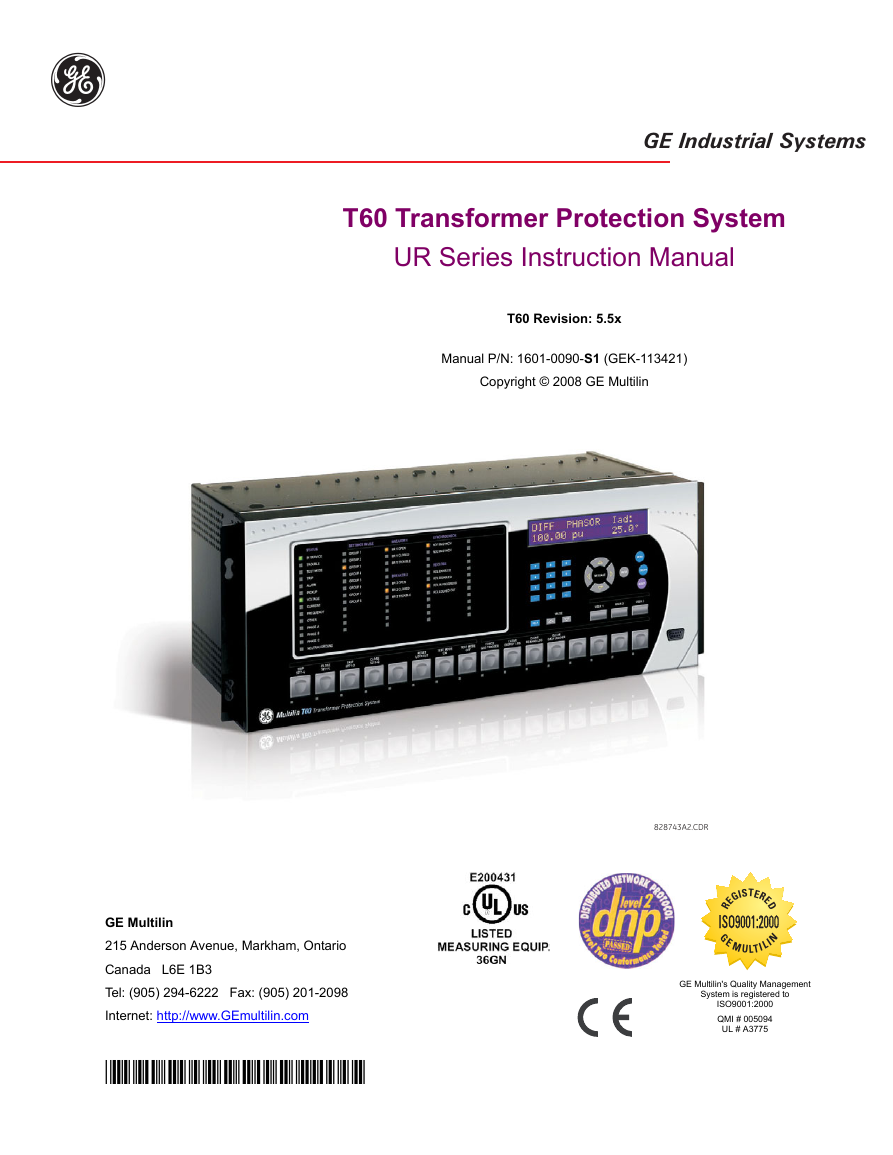
Title Page g GE Industrial Systems T60 Transformer Protection System UR Series Instruction Manual T60 Revision: 5.5x Manual P/N: 1601-0090-S1 (GEK-113421) Copyright © 2008 GE Multilin 828743A2.CDR GE Multilin 215 Anderson Avenue, Markham, Ontario Canada L6E 1B3 Tel: (905) 294-6222 Fax: (905) 201-2098 Internet: http://www.GEmultilin.com *1601-0090-S1* D E I S TER RE G ISO9001:2000 EMUL T I LIN G GE Multilin's Quality Management System is registered to ISO9001:2000 QMI # 005094 UL # A3775
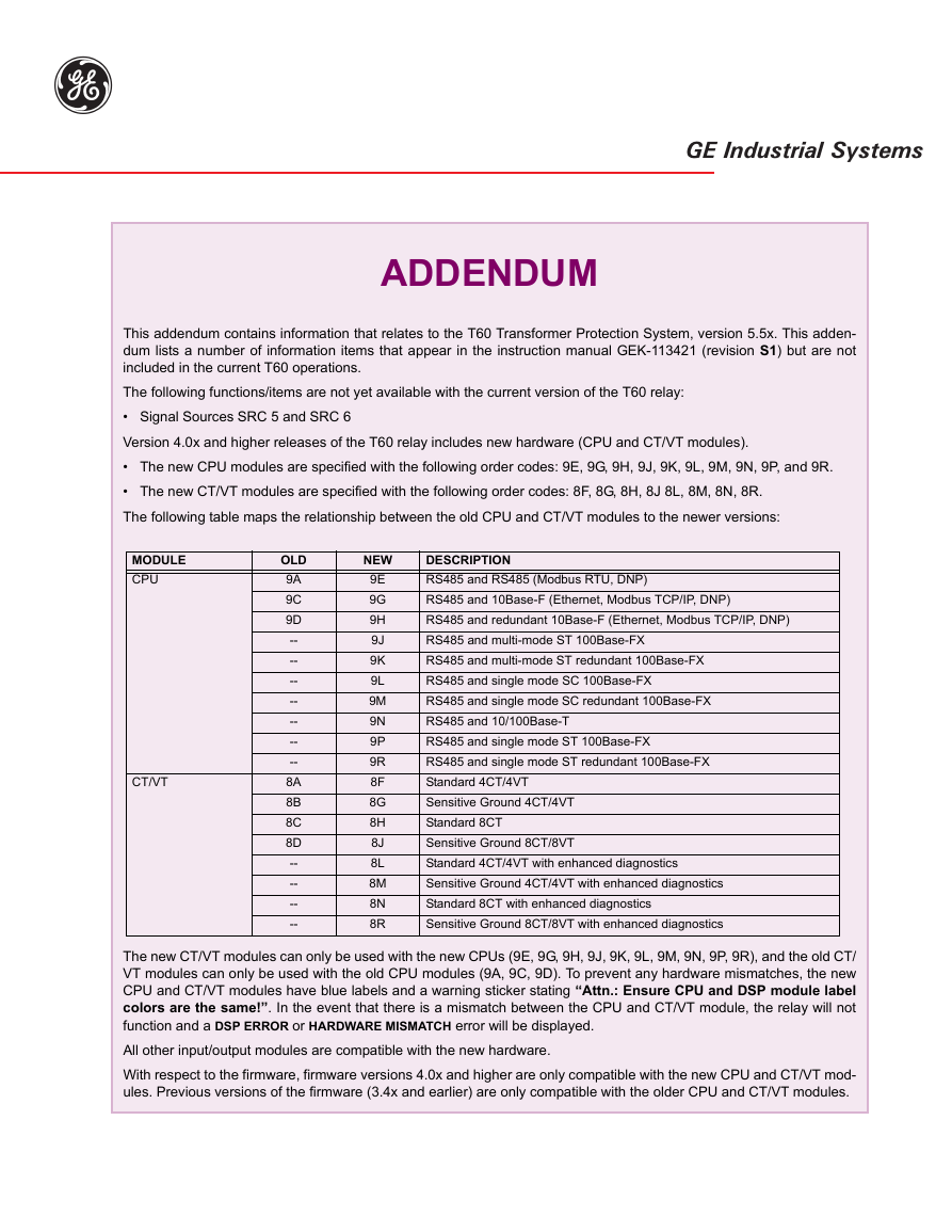
Addendum g GE Industrial Systems ADDENDUM This addendum contains information that relates to the T60 Transformer Protection System, version 5.5x. This adden- dum lists a number of information items that appear in the instruction manual GEK-113421 (revision S1) but are not included in the current T60 operations. The following functions/items are not yet available with the current version of the T60 relay: • Signal Sources SRC 5 and SRC 6 Version 4.0x and higher releases of the T60 relay includes new hardware (CPU and CT/VT modules). • The new CPU modules are specified with the following order codes: 9E, 9G, 9H, 9J, 9K, 9L, 9M, 9N, 9P, and 9R. • The new CT/VT modules are specified with the following order codes: 8F, 8G, 8H, 8J 8L, 8M, 8N, 8R. The following table maps the relationship between the old CPU and CT/VT modules to the newer versions: MODULE CPU CT/VT OLD 9A 9C 9D -- -- -- -- -- -- -- 8A 8B 8C 8D -- -- -- -- NEW 9E 9G 9H 9J 9K 9L 9M 9N 9P 9R 8F 8G 8H 8J 8L 8M 8N 8R DESCRIPTION RS485 and RS485 (Modbus RTU, DNP) RS485 and 10Base-F (Ethernet, Modbus TCP/IP, DNP) RS485 and redundant 10Base-F (Ethernet, Modbus TCP/IP, DNP) RS485 and multi-mode ST 100Base-FX RS485 and multi-mode ST redundant 100Base-FX RS485 and single mode SC 100Base-FX RS485 and single mode SC redundant 100Base-FX RS485 and 10/100Base-T RS485 and single mode ST 100Base-FX RS485 and single mode ST redundant 100Base-FX Standard 4CT/4VT Sensitive Ground 4CT/4VT Standard 8CT Sensitive Ground 8CT/8VT Standard 4CT/4VT with enhanced diagnostics Sensitive Ground 4CT/4VT with enhanced diagnostics Standard 8CT with enhanced diagnostics Sensitive Ground 8CT/8VT with enhanced diagnostics The new CT/VT modules can only be used with the new CPUs (9E, 9G, 9H, 9J, 9K, 9L, 9M, 9N, 9P, 9R), and the old CT/ VT modules can only be used with the old CPU modules (9A, 9C, 9D). To prevent any hardware mismatches, the new CPU and CT/VT modules have blue labels and a warning sticker stating “Attn.: Ensure CPU and DSP module label colors are the same!”. In the event that there is a mismatch between the CPU and CT/VT module, the relay will not function and a DSP ERROR or HARDWARE MISMATCH error will be displayed. All other input/output modules are compatible with the new hardware. With respect to the firmware, firmware versions 4.0x and higher are only compatible with the new CPU and CT/VT mod- ules. Previous versions of the firmware (3.4x and earlier) are only compatible with the older CPU and CT/VT modules.
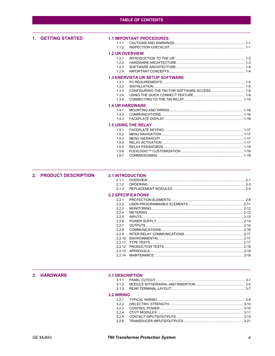
Table of Contents 1. GETTING STARTED 2. PRODUCT DESCRIPTION TABLE OF CONTENTS 1.1 IMPORTANT PROCEDURES 1.1.1 1.1.2 CAUTIONS AND WARNINGS ........................................................................... 1-1 INSPECTION CHECKLIST ................................................................................ 1-1 1.2 UR OVERVIEW INTRODUCTION TO THE UR ........................................................................... 1-2 HARDWARE ARCHITECTURE ......................................................................... 1-3 SOFTWARE ARCHITECTURE.......................................................................... 1-4 IMPORTANT CONCEPTS ................................................................................. 1-4 1.2.1 1.2.2 1.2.3 1.2.4 1.3.1 1.3.2 1.3.3 1.3.4 1.3.5 1.3 ENERVISTA UR SETUP SOFTWARE PC REQUIREMENTS ........................................................................................ 1-5 INSTALLATION.................................................................................................. 1-5 CONFIGURING THE T60 FOR SOFTWARE ACCESS .................................... 1-6 USING THE QUICK CONNECT FEATURE....................................................... 1-9 CONNECTING TO THE T60 RELAY............................................................... 1-15 1.4 UR HARDWARE 1.4.1 MOUNTING AND WIRING............................................................................... 1-16 COMMUNICATIONS........................................................................................ 1-16 1.4.2 1.4.3 FACEPLATE DISPLAY .................................................................................... 1-16 1.5 USING THE RELAY 1.5.1 FACEPLATE KEYPAD..................................................................................... 1-17 1.5.2 MENU NAVIGATION ....................................................................................... 1-17 1.5.3 MENU HIERARCHY ........................................................................................ 1-17 RELAY ACTIVATION....................................................................................... 1-17 1.5.4 RELAY PASSWORDS ..................................................................................... 1-18 1.5.5 1.5.6 FLEXLOGIC™ CUSTOMIZATION................................................................... 1-18 COMMISSIONING ........................................................................................... 1-19 1.5.7 2.1 INTRODUCTION 2.1.1 2.1.2 2.1.3 OVERVIEW........................................................................................................ 2-1 ORDERING........................................................................................................ 2-3 REPLACEMENT MODULES ............................................................................. 2-5 2.2 SPECIFICATIONS PROTECTION ELEMENTS ............................................................................... 2-8 2.2.1 2.2.2 USER-PROGRAMMABLE ELEMENTS........................................................... 2-11 2.2.3 MONITORING.................................................................................................. 2-12 2.2.4 METERING ...................................................................................................... 2-13 2.2.5 INPUTS ............................................................................................................ 2-13 POWER SUPPLY ............................................................................................ 2-14 2.2.6 OUTPUTS ........................................................................................................ 2-14 2.2.7 COMMUNICATIONS........................................................................................ 2-16 2.2.8 2.2.9 INTER-RELAY COMMUNICATIONS............................................................... 2-17 2.2.10 ENVIRONMENTAL .......................................................................................... 2-17 2.2.11 TYPE TESTS ................................................................................................... 2-17 2.2.12 PRODUCTION TESTS .................................................................................... 2-18 2.2.13 APPROVALS ................................................................................................... 2-18 2.2.14 MAINTENANCE ............................................................................................... 2-18 3. HARDWARE 3.1 DESCRIPTION 3.1.1 PANEL CUTOUT ............................................................................................... 3-1 3.1.2 MODULE WITHDRAWAL AND INSERTION ..................................................... 3-5 REAR TERMINAL LAYOUT............................................................................... 3-7 3.1.3 3.2 WIRING 3.2.1 3.2.2 3.2.3 3.2.4 3.2.5 3.2.6 TYPICAL WIRING.............................................................................................. 3-9 DIELECTRIC STRENGTH ............................................................................... 3-10 CONTROL POWER ......................................................................................... 3-10 CT/VT MODULES ............................................................................................ 3-11 CONTACT INPUTS/OUTPUTS ....................................................................... 3-13 TRANSDUCER INPUTS/OUTPUTS................................................................ 3-21 GE Multilin T60 Transformer Protection System v
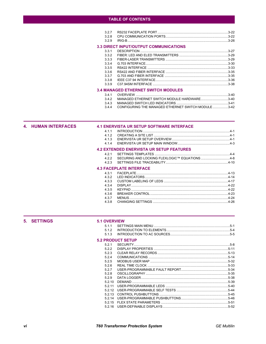
TABLE OF CONTENTS 3.2.7 3.2.8 3.2.9 RS232 FACEPLATE PORT..............................................................................3-22 CPU COMMUNICATION PORTS.....................................................................3-22 IRIG-B...............................................................................................................3-26 3.3 DIRECT INPUT/OUTPUT COMMUNICATIONS 3.3.1 3.3.2 3.3.3 3.3.4 3.3.5 3.3.6 3.3.7 3.3.8 3.3.9 DESCRIPTION .................................................................................................3-27 FIBER: LED AND ELED TRANSMITTERS ......................................................3-29 FIBER-LASER TRANSMITTERS .....................................................................3-29 G.703 INTERFACE...........................................................................................3-30 RS422 INTERFACE .........................................................................................3-33 RS422 AND FIBER INTERFACE .....................................................................3-35 G.703 AND FIBER INTERFACE ......................................................................3-35 IEEE C37.94 INTERFACE................................................................................3-36 C37.94SM INTERFACE ...................................................................................3-38 3.4 MANAGED ETHERNET SWITCH MODULES 3.4.1 OVERVIEW ......................................................................................................3-40 3.4.2 MANAGED ETHERNET SWITCH MODULE HARDWARE..............................3-40 3.4.3 MANAGED SWITCH LED INDICATORS .........................................................3-41 CONFIGURING THE MANAGED ETHERNET SWITCH MODULE.................3-42 3.4.4 4.1 ENERVISTA UR SETUP SOFTWARE INTERFACE INTRODUCTION ................................................................................................4-1 CREATING A SITE LIST ....................................................................................4-1 ENERVISTA UR SETUP OVERVIEW................................................................4-1 ENERVISTA UR SETUP MAIN WINDOW..........................................................4-3 4.1.1 4.1.2 4.1.3 4.1.4 4.2.1 4.2.2 4.2.3 4.2 EXTENDED ENERVISTA UR SETUP FEATURES SETTINGS TEMPLATES ...................................................................................4-4 SECURING AND LOCKING FLEXLOGIC™ EQUATIONS ................................4-8 SETTINGS FILE TRACEABILITY.....................................................................4-10 4.3 FACEPLATE INTERFACE FACEPLATE.....................................................................................................4-13 4.3.1 LED INDICATORS............................................................................................4-14 4.3.2 CUSTOM LABELING OF LEDS .......................................................................4-17 4.3.3 DISPLAY...........................................................................................................4-22 4.3.4 KEYPAD ...........................................................................................................4-22 4.3.5 4.3.6 BREAKER CONTROL ......................................................................................4-23 4.3.7 MENUS.............................................................................................................4-24 4.3.8 CHANGING SETTINGS ...................................................................................4-26 5.1 OVERVIEW 5.1.1 5.1.2 5.1.3 SETTINGS MAIN MENU ....................................................................................5-1 INTRODUCTION TO ELEMENTS......................................................................5-4 INTRODUCTION TO AC SOURCES..................................................................5-5 4. HUMAN INTERFACES 5. SETTINGS 5.2 PRODUCT SETUP SECURITY..........................................................................................................5-8 5.2.1 DISPLAY PROPERTIES ..................................................................................5-11 5.2.2 CLEAR RELAY RECORDS ..............................................................................5-13 5.2.3 5.2.4 COMMUNICATIONS ........................................................................................5-14 5.2.5 MODBUS USER MAP ......................................................................................5-32 REAL TIME CLOCK .........................................................................................5-33 5.2.6 USER-PROGRAMMABLE FAULT REPORT....................................................5-34 5.2.7 5.2.8 OSCILLOGRAPHY ...........................................................................................5-35 5.2.9 DATA LOGGER................................................................................................5-38 5.2.10 DEMAND ..........................................................................................................5-39 5.2.11 USER-PROGRAMMABLE LEDS .....................................................................5-40 5.2.12 USER-PROGRAMMABLE SELF TESTS .........................................................5-44 5.2.13 CONTROL PUSHBUTTONS ............................................................................5-45 5.2.14 USER-PROGRAMMABLE PUSHBUTTONS....................................................5-46 5.2.15 FLEX STATE PARAMETERS ..........................................................................5-51 5.2.16 USER-DEFINABLE DISPLAYS ........................................................................5-52 vi T60 Transformer Protection System GE Multilin
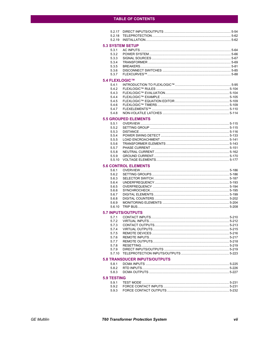
TABLE OF CONTENTS 5.2.17 DIRECT INPUTS/OUTPUTS ........................................................................... 5-54 5.2.18 TELEPROTECTION......................................................................................... 5-62 5.2.19 INSTALLATION................................................................................................ 5-62 5.3 SYSTEM SETUP 5.4 FLEXLOGIC™ 5.3.1 5.3.2 5.3.3 5.3.4 5.3.5 5.3.6 5.3.7 5.4.1 5.4.2 5.4.3 5.4.4 5.4.5 5.4.6 5.4.7 5.4.8 AC INPUTS ...................................................................................................... 5-64 POWER SYSTEM............................................................................................ 5-66 SIGNAL SOURCES ......................................................................................... 5-67 TRANSFORMER ............................................................................................. 5-69 BREAKERS...................................................................................................... 5-81 DISCONNECT SWITCHES ............................................................................. 5-85 FLEXCURVES™.............................................................................................. 5-88 INTRODUCTION TO FLEXLOGIC™............................................................... 5-95 FLEXLOGIC™ RULES .................................................................................. 5-104 FLEXLOGIC™ EVALUATION........................................................................ 5-104 FLEXLOGIC™ EXAMPLE ............................................................................. 5-105 FLEXLOGIC™ EQUATION EDITOR ............................................................. 5-109 FLEXLOGIC™ TIMERS................................................................................. 5-109 FLEXELEMENTS™ ....................................................................................... 5-110 NON-VOLATILE LATCHES ........................................................................... 5-114 5.5 GROUPED ELEMENTS OVERVIEW.................................................................................................... 5-115 5.5.1 SETTING GROUP ......................................................................................... 5-115 5.5.2 DISTANCE ..................................................................................................... 5-116 5.5.3 POWER SWING DETECT ............................................................................. 5-133 5.5.4 LOAD ENCROACHMENT.............................................................................. 5-141 5.5.5 TRANSFORMER ELEMENTS ....................................................................... 5-143 5.5.6 PHASE CURRENT ........................................................................................ 5-151 5.5.7 NEUTRAL CURRENT.................................................................................... 5-162 5.5.8 5.5.9 GROUND CURRENT..................................................................................... 5-170 5.5.10 VOLTAGE ELEMENTS.................................................................................. 5-177 5.6 CONTROL ELEMENTS OVERVIEW.................................................................................................... 5-186 5.6.1 SETTING GROUPS ....................................................................................... 5-186 5.6.2 SELECTOR SWITCH..................................................................................... 5-187 5.6.3 UNDERFREQUENCY.................................................................................... 5-193 5.6.4 OVERFREQUENCY ...................................................................................... 5-194 5.6.5 SYNCHROCHECK......................................................................................... 5-195 5.6.6 DIGITAL ELEMENTS..................................................................................... 5-199 5.6.7 5.6.8 DIGITAL COUNTERS .................................................................................... 5-202 5.6.9 MONITORING ELEMENTS ........................................................................... 5-204 5.6.10 TRIP BUS....................................................................................................... 5-208 5.7 INPUTS/OUTPUTS 5.7.1 CONTACT INPUTS........................................................................................ 5-210 5.7.2 VIRTUAL INPUTS.......................................................................................... 5-212 5.7.3 CONTACT OUTPUTS.................................................................................... 5-213 5.7.4 VIRTUAL OUTPUTS...................................................................................... 5-215 5.7.5 REMOTE DEVICES ....................................................................................... 5-216 5.7.6 REMOTE INPUTS.......................................................................................... 5-217 5.7.7 REMOTE OUTPUTS...................................................................................... 5-218 5.7.8 RESETTING................................................................................................... 5-219 5.7.9 DIRECT INPUTS/OUTPUTS ......................................................................... 5-219 5.7.10 TELEPROTECTION INPUTS/OUTPUTS ...................................................... 5-223 5.8 TRANSDUCER INPUTS/OUTPUTS DCMA INPUTS .............................................................................................. 5-225 RTD INPUTS.................................................................................................. 5-226 DCMA OUTPUTS .......................................................................................... 5-227 TEST MODE .................................................................................................. 5-231 FORCE CONTACT INPUTS .......................................................................... 5-231 FORCE CONTACT OUTPUTS ...................................................................... 5-232 5.9 TESTING 5.8.1 5.8.2 5.8.3 5.9.1 5.9.2 5.9.3 GE Multilin T60 Transformer Protection System vii
6. ACTUAL VALUES 7. COMMANDS AND TARGETS 8. COMMISSIONING TABLE OF CONTENTS 6.1 OVERVIEW 6.1.1 ACTUAL VALUES MAIN MENU.........................................................................6-1 6.2 STATUS CONTACT INPUTS ............................................................................................6-3 6.2.1 VIRTUAL INPUTS ..............................................................................................6-3 6.2.2 REMOTE INPUTS ..............................................................................................6-3 6.2.3 TELEPROTECTION INPUTS .............................................................................6-4 6.2.4 CONTACT OUTPUTS ........................................................................................6-4 6.2.5 VIRTUAL OUTPUTS ..........................................................................................6-5 6.2.6 REMOTE DEVICES............................................................................................6-5 6.2.7 DIGITAL COUNTERS.........................................................................................6-6 6.2.8 6.2.9 SELECTOR SWITCHES ....................................................................................6-6 6.2.10 FLEX STATES....................................................................................................6-6 6.2.11 ETHERNET ........................................................................................................6-6 6.2.12 DIRECT INPUTS ................................................................................................6-7 6.2.13 DIRECT DEVICES STATUS ..............................................................................6-7 6.2.14 EGD PROTOCOL STATUS................................................................................6-8 6.2.15 TELEPROTECTION CHANNEL TESTS.............................................................6-8 6.2.16 ETHERNET SWITCH .........................................................................................6-9 6.3 METERING 6.3.1 METERING CONVENTIONS ...........................................................................6-10 TRANSFORMER ..............................................................................................6-13 6.3.2 SOURCES ........................................................................................................6-14 6.3.3 SYNCHROCHECK ...........................................................................................6-19 6.3.4 TRACKING FREQUENCY................................................................................6-19 6.3.5 6.3.6 FLEXELEMENTS™..........................................................................................6-19 IEC 61580 GOOSE ANALOG VALUES ...........................................................6-20 6.3.7 VOLTS PER HERTZ.........................................................................................6-20 6.3.8 6.3.9 RESTRICTED GROUND FAULT......................................................................6-21 6.3.10 TRANSDUCER INPUTS/OUTPUTS.................................................................6-21 6.4 RECORDS 6.4.1 6.4.2 6.4.3 6.4.4 6.4.5 USER-PROGRAMMABLE FAULT REPORTS .................................................6-22 EVENT RECORDS...........................................................................................6-22 OSCILLOGRAPHY ...........................................................................................6-22 DATA LOGGER................................................................................................6-23 BREAKER MAINTENANCE .............................................................................6-23 6.5 PRODUCT INFORMATION 6.5.1 MODEL INFORMATION...................................................................................6-24 6.5.2 FIRMWARE REVISIONS..................................................................................6-24 7.1 COMMANDS 7.1.1 7.1.2 7.1.3 7.1.4 7.1.5 7.2.1 7.2.2 7.2.3 7.2 TARGETS COMMANDS MENU...........................................................................................7-1 VIRTUAL INPUTS ..............................................................................................7-1 CLEAR RECORDS.............................................................................................7-1 SET DATE AND TIME ........................................................................................7-2 RELAY MAINTENANCE.....................................................................................7-2 TARGETS MENU ...............................................................................................7-3 TARGET MESSAGES ........................................................................................7-3 RELAY SELF-TESTS .........................................................................................7-3 8.1 DIFFERENTIAL CHARACTERISTIC TEST 8.1.1 DESCRIPTION ...................................................................................................8-1 8.2 DIFFERENTIAL CHARACTERISTIC TEST EXAMPLES 8.2.1 8.2.2 8.2.3 8.2.4 INTRODUCTION ................................................................................................8-3 TEST EXAMPLE 1..............................................................................................8-4 TEST EXAMPLE 2..............................................................................................8-9 TEST EXAMPLE 3............................................................................................8-10 viii T60 Transformer Protection System GE Multilin
分享到:
收藏