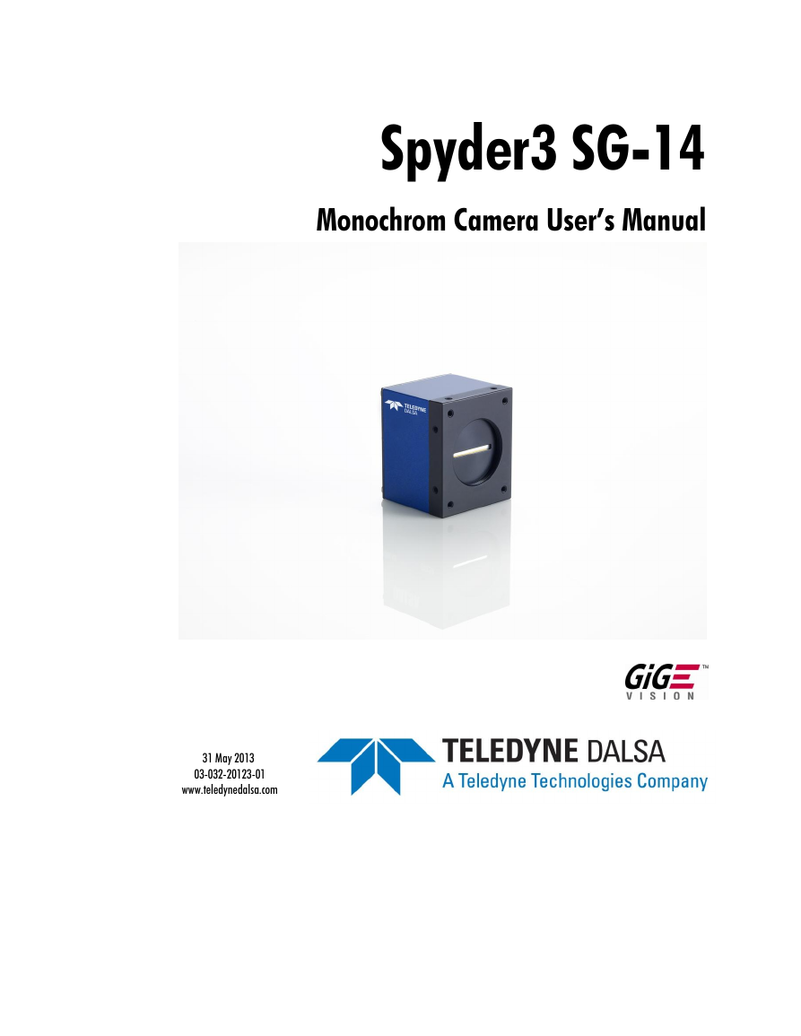
Spyder3 SG-14
Monochrom Camera User’s Manual
31 May 2013
03-032-20123-01
www.teledynedalsa.com
�
2
Spyder3 GigE Vision SG-14 Monochrome Cameras User’s Manual
© 2013 Teled yne DALSA Inc. All inform ation p rovid ed in this m anual is believed to be accu rate and reliable. N o resp onsibility is
assu m ed by Teled yne DALSA for its u se. Teled yne DALSA reserves the right to make changes to this inform ation w ithou t notice.
Rep rod u ction of this manu al in w hole or in p art, by any m eans, is p rohibited w ithou t p rior p erm ission having been obtained from
Teled yne DALSA.
About Teledyne Technologies and Teledyne DALSA, Inc.
Teled yne Technologies is a lead ing p rovid er of sop histicated electronic su bsystem s, in stru m entation and com m u nication p rod u cts,
engineered system s, aerosp ace engines, and energy and pow er generation system s. Teled yne Technologies’ op erations are p rim ari ly
located in the United States, the United Kingd om and Mexico. For more inform ation, vis it Teled yne Technologies’ w ebsite at
w w w .teled yne.com.
Teled yne DALSA, a Teled yne Technologies com pany, is an international lead er in high p erformance d igital im aging and
sem icond u ctors w ith ap p roxim ately 1,000 em p loyees w orld w id e, head qu artered in Waterlo o, Ontario, Canad a. Established in 1980,
the com pany d esigns, d evelop s, manu factu res and markets d igital im aging p rod u cts and solu tions, in ad d ition to p rovid ing MEMS
p rod u cts and services. For more inform ation, visit Teled yne DALSA’s w ebsite at w w w .teled y ned alsa.com .
Support
For fu rther inform ation not inclu d ed in this manu al, or for inform ation on Teled yne DALSA’s extensive line of im age sensing
p rod u cts, p lease contact:
North America
Europe
Asia Pacific
605 McMu rray Rd
Waterloo, ON N 2V 2E9
Canad a
Tel: 519 886 6000
Fax: 519 886 8023
w w w .teled yned alsa.com
sales.am ericas@teled yned alsa.com
su p p ort@teled yned alsa.com
Teled yne DALSA Gm bH
Felix-Wankel-Strasse 1
D-82152 Krailling (Mu nich)
Germ any
Tel: +49 - 89 - 89545730
Fax: +49 - 89 – 895457346
w w w . teled yned alsa.com
sales.eu rop e@teled yned alsa.com
su p p ort@teled yned alsa.com
Ikebu ku ro East 13F
3-4-3 H igashi-Ikebu ku ro
Toshim a-ku , Tokyo 170-0013
Jap an
Tel: 81 3 5960 6353
Fax: 81 3 5960 6354 (fax)
w w w .teled yned alsa.com
sales.asia@teled yned alsa.com
su p p ort@teled yned alsa.com
Industry Standards
Sp yd er GEV cam eras are 100% com p liant w ith the GigE Vision 1.0 sp ecification. This sp ecification d efines
the com m u nication interface p rotocol u sed by GigE Vision d evices. For m ore inform ation on these
requ irem ents refer to the follow ing site:
http :/ / w w w .m achinevisiononline.org/ p u blic/ articles/ d etails.cfm ?id =2761
Sp yd er GEV cam eras im p lem ent a su p erset of the GenICam ™ sp ecification w hich d efines d evice
cap abilities. This d escrip tion takes the form of an XML d evice d escrip tion file resp ecting the synta x
d efined by the GenAp i m od u le of the GenICam sp ecification. For m ore inform ation on these
requ irem ents refer to the follow ing site: w w w .genicam .org.
03-032-20123-01
Teledyne DALSA
�
Spyder3 GigE Vision SG-14 Monochrome Cameras User’s Manual
3
Contents
The Spyder3 SG-14 Cameras ________________________________________________________________________ 6
Camera Highlights ............................................................................................................................................................. 6
Camera Performance Specifications .................................................................................................................................. 7
Certifications ...................................................................................................................................................................... 10
Responsivity ....................................................................................................................................................................... 11
Mechanicals ........................................................................................................................................................................ 12
Mounting ......................................................................................................................................................... 14
Image Sensor ..................................................................................................................................................................... 14
Software and Hardware Setup .......................................................................................................................................... 15
Host System Requirements ............................................................................................................................. 15
Network Adapter Requirements ..................................................................................................................... 15
Ethernet Switch Requirements ........................................................................................................................ 15
Setup Steps: Overview ....................................................................................................................................................... 15
1. Install and Configure Ethernet Network Card ............................................................................................. 15
2. Connect Power, Ethernet and I/O Cables .................................................................................................... 15
3. Establish communicating with the camera .................................................................................................. 16
4. Check camera LED, settings and test pattern .............................................................................................. 16
5. Operate the Camera ................................................................................................................................... 16
Step 1. Ethernet Network Card: Install and Configure ...................................................................................................... 17
Install Network Card ....................................................................................................................................... 17
Configure Network Card ................................................................................................................................. 17
Step 2. Connect Power, Ethernet, and Trigger Cables ....................................................................................................... 20
Power Connector ............................................................................................................................................. 20
Ethernet Connector and Ethernet LED ............................................................................................................ 21
Status LED ....................................................................................................................................................... 21
GPIO Connector: External Input ..................................................................................................................... 22
GPIO Isolation................................................................................................................................................. 22
GPIO Configuration ........................................................................................................................................ 22
TTL Inputs and Outputs................................................................................................................................... 23
Step 3. Establish Communication with the Camera ........................................................................................................... 24
Power on the camera ...................................................................................................................................... 24
Connect to the camera .................................................................................................................................... 24
Check LED Status ............................................................................................................................................ 24
Software Interface ........................................................................................................................................... 24
Using Sapera CamExpert with Spyder3 Cameras .............................................................................................................. 25
CamExpert Panes ............................................................................................................................................ 26
Step 4. Camera Settings and Test Patterns ....................................................................................................................... 28
Review a Test Pattern Image .......................................................................................................................... 28
Camera Operation _______________________________________________________________________________ 29
Factory Settings ................................................................................................................................................................. 29
Check Camera and Sensor Information ............................................................................................................................. 30
Verify Temperature and Voltage ....................................................................................................................................... 30
Saving and Restoring Camera Settings ............................................................................................................................. 31
Teledyne DALSA
03-032-20123-01
�
4
Spyder3 GigE Vision SG-14 Monochrome Cameras User’s Manual
Timing: Exposure and Synchronization ............................................................................................................................. 33
Timing ............................................................................................................................................................. 34
Exposure Controls .............................................................................................................................................................. 35
Set the Exposure Mode.................................................................................................................................... 35
Exposure Modes in Detail ............................................................................................................................... 36
Line Rate ........................................................................................................................................................................... 37
Exposure Time ................................................................................................................................................................... 38
Triggers.............................................................................................................................................................................. 38
Input / Output Control ....................................................................................................................................................... 39
Gain, Black Level, and Background .................................................................................................................................. 40
Image Size ......................................................................................................................................................................... 41
Pixel Format ...................................................................................................................................................................... 42
Sensitivity Mode ................................................................................................................................................................. 42
Sensor Direction Control .................................................................................................................................................... 42
Sensor Shift Direction ..................................................................................................................................... 43
Binning .............................................................................................................................................................................. 44
Resetting the Camera ........................................................................................................................................................ 44
Camera Calibration_______________________________________________________________________________ 45
Processing Chain Overview and Description ................................................................................................... 45
Analog Gain and Offset Adjustment .................................................................................................................................. 47
Calibrate the Camera to Remove Non-Uniformity (Flat Field Correction) ........................................................................ 49
Digital Signal Processing ................................................................................................................................ 51
Appendix A: Clear Dark Current ______________________________________________________________________ 55
Gate Dark Current Clear ................................................................................................................................. 55
Auto Mode (srm 0) .......................................................................................................................................... 55
Immediate read out mode (default, srm 2) .................................................................................................... 56
Gate dark current clear mode (always on, srm 1) .......................................................................................... 56
Setting the Readout Mode .............................................................................................................................. 57
Appendix B: Sensitivity Mode ________________________________________________________________________ 58
Sensitivity Mode and Pixel Readout ............................................................................................................... 58
Appendix C: GPIO Control __________________________________________________________________________ 60
GPIO Getting Started: Beginner Mode .............................................................................................................................. 60
The GPIO Connector ........................................................................................................................................ 60
Configure GPIO Signal Levels ......................................................................................................................... 61
Examples: Setting the Camera Modes ............................................................................................................................... 62
Free Run Mode: Internal Line Trigger, Internal Direction Control, Internal frame trigger ........................... 62
Internal Line Trigger, External Direction Control, Internal frame trigger...................................................... 64
External Line Trigger, Internal Direction Control, Internal frame trigger...................................................... 65
External Line Trigger, External Direction Control from Rotary Encoder......................................................... 66
External Frame Trigger: Frame Start Trigger mode ..................................................................................... 68
Outputs .............................................................................................................................................................................. 71
Trigger Settings: GURU Mode ........................................................................................................................................... 73
Pulse Generator .............................................................................................................................................. 76
Rescaler ........................................................................................................................................................... 78
Counter ........................................................................................................................................................... 80
03-032-20123-01
Teledyne DALSA
�
Spyder3 GigE Vision SG-14 Monochrome Cameras User’s Manual
5
Input Debouncing ........................................................................................................................................... 81
Timestamp Counter ......................................................................................................................................... 82
Delayer ........................................................................................................................................................... 84
PLC Control ........................................................................................................................................................................ 84
The PLC Control Block ..................................................................................................................................... 85
GPIO Output Labels ........................................................................................................................................ 87
Signal Routing Block ......................................................................................................................................................... 89
How the Signal Routing Block Works ............................................................................................................. 90
How the Lookup Table Works ......................................................................................................................... 93
Appendix D: EMC Declaration ________________________________________________________________________ 94
Appendix E: Setting up the FVAL ______________________________________________________________________ 95
Examples: Setting the FVAL .............................................................................................................................................. 99
Revision History _________________________________________________________________________________ 102
Index ________________________________________________________________________________________ 103
Teledyne DALSA
03-032-20123-01
�
6
Spyder3 GigE Vision SG-14 Monochrome Cameras User’s Manual
The Spyder3 SG-14 Cameras
Camera Highlights
The Sp yd er3 SG-14 GigE Vision (GEV) are high sensitivity d u al-line scan cam eras. When op erating in
high sensitivity (d u al line scan) m od e the Sp yd er3 GEV cam era has 3x the resp onsivity of Teled yne
DALSA’s Sp yd er2 line scan cam era. Plu s, the GigE Vision interface elim inates the need for a fram e
grabber, resu lting in significant system cost savings.
The Sp yd er3 cam eras are su p p orted by Teled yne DALSA Sap era™ softw are libraries featu ring
Cam Exp ert for sim p lified cam era set-u p and configu ration.
Features
Broad band resp onsivity u p to 408 ±16 DN (nJ/ cm 2) @ 10d B gain
1024, 2048, or 4096 x 2 p ixels, 14 µm x 14 µm (1k and 2k) and 10 µm x 10 µm (4k) p ixel p itch, 100 %
fill factor
H igh or low sp eed (40 or 80 MH z)
Up to 68 KH z line rates
Dynam ic range u p to 1400 : 1
Data transm ission u p to 100 m eters
RoH S and CE com p liant
GenICam -com p liant
Program m able gain , offset, exp osu re tim e and line rate, trigger m od e, test p attern ou tp u t, and cam era
d iagnostics
Tall p ixel, high sensitivity, or low sensitivity m od e available
Flat-field correction—m inim izes lens vignetting, non -u niform lighting, and sensor FPN and PRN U
Applications
100 % p rint insp ection (lottery tickets, stam p s, bank notes, p ay checks)
FPD insp ection
Pick and p lace
Container insp ection
Wood / tile / steel insp ection
Postal sorting
Glass bottle insp ection
Food insp ection
Web insp ection
Ind u strial m etrology
03-032-20123-01
Teledyne DALSA
�
Spyder3 GigE Vision SG-14 Monochrome Cameras User’s Manual
7
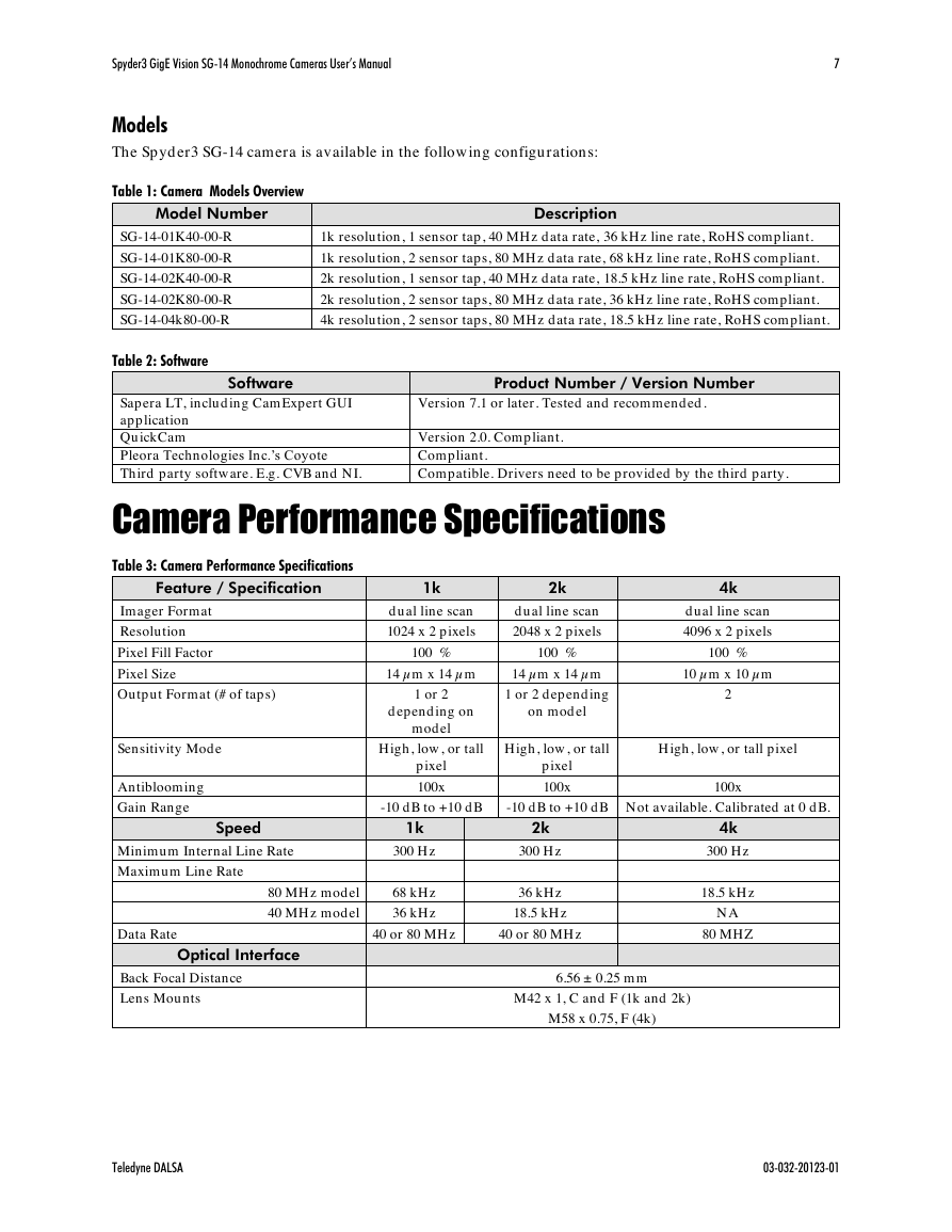
Models
The Sp yd er3 SG-14 cam era is available in the follow ing configu rations:
Table 1: Camera Models Overview
Model Number
Description
SG-14-01K40-00-R
SG-14-01K80-00-R
SG-14-02K40-00-R
SG-14-02K80-00-R
SG-14-04k80-00-R
Table 2: Software
1k resolu tion, 1 sensor tap , 40 MH z d ata rate, 36 kH z line rate, RoH S com p liant.
1k resolu tion, 2 sensor tap s, 80 MH z d ata rate, 68 kH z line rate, RoH S com p liant.
2k resolu tion, 1 sensor tap , 40 MH z d ata rate, 18.5 kH z line rate, RoH S com p liant.
2k resolu tion, 2 sensor tap s, 80 MH z d ata r ate, 36 kH z line rate, RoH S com p liant.
4k resolu tion, 2 sensor tap s, 80 MH z d ata rate, 18.5 kH z line rate, RoH S com p liant.
Software
Product Number / Version Number
Sap era LT, inclu d ing Cam Expert GUI
ap p lication
Qu ickCam
Pleora Technologies Inc.’s Coyote
Third p arty softw are. E.g. CVB and N I.
Version 7.1 or later. Tested and recom m end ed .
Version 2.0. Com p liant.
Com p liant.
Com p atible. Drivers need to be p rovid ed by the third p arty.
Camera Performance Specifications
Table 3: Camera Performance Specifications
Feature / Specification
1k
2k
4k
Im ager Form at
Resolu tion
Pixel Fill Factor
Pixel Size
d u al line scan
d u al line scan
1024 x 2 p ixels
2048 x 2 p ixels
100 %
100 %
d u al line scan
4096 x 2 p ixels
100 %
14 µm x 14 µm
14 µm x 14 µm
10 µm x 10 µm
Ou tp u t Form at (# of tap s)
1 or 2
1 or 2 d ep end ing
2
d ep end ing on
on m od el
m od el
Sensitivity Mod e
H igh, low , or tall
H igh, low , or tall
H igh, low , or tall p ixel
Antibloom ing
Gain Range
p ixel
100x
p ixel
100x
100x
-10 d B to +10 d B
-10 d B to +10 d B N ot available. Calibrated at 0 d B.
Speed
1k
2k
Minim u m Internal Line Rate
Maxim u m Line Rate
300 H z
80 MH z m od el
68 kH z
40 MH z m od el
36 kH z
300 H z
36 kH z
18.5 kH z
Data Rate
40 or 80 MH z
40 or 80 MH z
Optical Interface
4k
300 H z
18.5 kH z
N A
80 MH Z
Back Focal Distance
Lens Mou nts
6.56 ± 0.25 m m
M42 x 1, C and F (1k and 2k)
M58 x 0.75, F (4k)
Teledyne DALSA
03-032-20123-01
�
8
Spyder3 GigE Vision SG-14 Monochrome Cameras User’s Manual
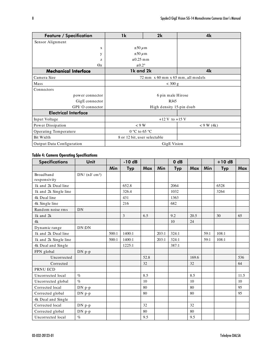
Feature / Specification
1k
2k
Sensor Alignm ent
x
y
z
z
±50 µm
±50 µm
±0.25 m m
±0.2°
4k
Mechanical Interface
1k and 2k
4k
Cam era Size
Mass
Connectors
p ow er connector
GigE connector
GPI/ O connector
72 m m x 60 m m x 65 m m , all m od els
< 300 g
6 p in m ale H irose
RJ45
H igh d ensity 15-p in d su b
Electrical Interface
Inp u t Voltage
Pow er Dissip ation
Op erating Tem p eratu re
Bit Wid th
Ou tp u t Data Configu ration
Table 4: Camera Operating Specifications
+12 V to +15 V
< 9 W
0 °C to 65 °C
8 or 12 bit, u ser selectable
< 9 W (4k)
GigE Vision
Specifications
Unit
-10 dB
0 dB
+10 dB
Min
Typ Max Min
Typ Max Min
Typ
Max
Broad band
resp onsivity
1k and 2k Du al line
1k and 2k Single line
4k Du al line
4k Single line
DN / (nJ/ cm ²)
Rand om noise rm s
DN
1k and 2k
4k
Dynam ic range
DN :DN
1k and 2k Du al line
1k and 2k Single line
4k Du al and Single
FPN global
DN p -p
Uncorrected
Corrected
PRN U ECD
Uncorrected local
Uncorrected global
%
%
Corrected local
Corrected global
DN p -p
DN p -p
4k Du al and Single
Corrected local
Corrected global
DN p -p
DN p -p
Uncorrected local
%
652.8
326.4
431
216
3
500:1 1400:1
500:1 1400:1
1225:1
6.5
52.8
32
8.5
10
80
80
32
80
9.5
2064
1032
1363
682
9.2
10
203:1 324:1
203:1 324:1
387:1
20.5
24
169.6
32
8.5
10
80
80
32
80
9.5
6528
3264
30
59:1
108:1
59:1
108:1
65
536
64
11.5
10
95
95
03-032-20123-01
Teledyne DALSA
�




 2023年江西萍乡中考道德与法治真题及答案.doc
 2012年重庆南川中考生物真题及答案.doc
 2013年江西师范大学地理学综合及文艺理论基础考研真题.doc
 2020年四川甘孜小升初语文真题及答案I卷.doc
 2020年注册岩土工程师专业基础考试真题及答案.doc
 2023-2024学年福建省厦门市九年级上学期数学月考试题及答案.doc
 2021-2022学年辽宁省沈阳市大东区九年级上学期语文期末试题及答案.doc
 2022-2023学年北京东城区初三第一学期物理期末试卷及答案.doc
 2018上半年江西教师资格初中地理学科知识与教学能力真题及答案.doc
 2012年河北国家公务员申论考试真题及答案-省级.doc
 2020-2021学年江苏省扬州市江都区邵樊片九年级上学期数学第一次质量检测试题及答案.doc
 2022下半年黑龙江教师资格证中学综合素质真题及答案.doc