logo资料库

mipi_C-PHY_specification_v1-2.pdf

第1页 / 共200页
第2页 / 共200页
第3页 / 共200页
第4页 / 共200页
第5页 / 共200页
第6页 / 共200页
第7页 / 共200页
第8页 / 共200页
资料共200页,剩余部分请下载后查看
Contents
Figures
Tables
Release History
1 Introduction
1.1 Scope
1.2 Purpose
2 Terminology
2.1 Use of Special Terms
2.2 Definitions
2.3 Abbreviations
2.4 Acronyms
3 References
4 C-PHY Overview
4.1 Summary of PHY Functionality
4.1.1 Summary of Lane Signaling States
4.1.2 Representation of Symbols in High-Speed Mode
4.1.3 Representation of High-Speed Signaling States
4.2 Mandatory Functionality
5 Architecture
5.1 Lane Modules
5.2 Master and Slave
5.3 High Frequency Clock Generation
5.4 Lanes and the PHY-Protocol Interface
5.5 Selectable Lane Options
5.6 Lane Module Types
5.6.1 Unidirectional Lane
5.6.2 Bi-Directional Lanes
5.6.2.1 Bi-Directional Lane Modes
5.6.2.2 Bi-Directional Lane with High-Speed Reverse Communication
5.7 Configurations
5.7.1 Unidirectional Configurations
5.7.1.1 PHY Configuration with a Single Lane
5.7.1.2 PHY Configuration with Multiple Lanes
5.7.1.3 Dual-Simplex (Two Directions with Unidirectional Lanes)
5.7.2 Bi-Directional Half-Duplex Configurations
5.7.2.1 PHY Configurations with a Bi-Directional Single Lane
5.7.2.2 PHY Configurations with Multiple Lanes
5.7.3 Mixed Lane Configurations
6 Global Operation
6.1 Transmission Data Structure
6.1.1 Data Units
6.1.2 Bit Order, Serialization, and De-Serialization
6.1.3 Encoding, Decoding, Mapping and De-Mapping
6.1.3.1 Wire States
6.1.3.2 Symbol Encoding and Decoding
6.1.3.2.1 Encoding
6.1.3.2.2 Decoding
6.1.3.3 16-to-7 Mapping and 7-to-16 De-Mapping Circuit Implementation
6.1.3.3.1 Tx 16-Bit to 7-Symbol Mapper
6.1.3.3.2 Rx 7-Symbol to 16-Bit De-Mapper
6.1.4 Data Buffering
6.2 Lane States and Line Levels
6.2.1 HS and LP Mode Line States and Line Levels
6.2.2 ALP Mode Line States and Line Levels
6.3 Operating Modes: Control, High-Speed, and Escape
6.3.1 HS and LP Operating Modes
6.3.2 ALP Operating Modes
6.4 High-Speed Data Transmission
6.4.1 Burst Payload Data
6.4.2 Start-of-Transmission
6.4.3 End-of-Transmission
6.4.4 HS Data Transmission Burst
6.4.4.1 Sync Word for Packet Header Resynchronization
6.4.4.2 Sync Word Sync Type
6.4.5 Alternate Low Power (ALP) Mode Transmission Burst
6.4.5.1 Stop Code and ULPS Code
6.4.5.2 Trigger Codes
6.4.5.3 Spacer Code
6.4.5.4 LPDT Start Code and LPDT Nibble Code
6.4.5.5 Post2 Code
6.4.5.6 ALP Timing Parameters
6.4.5.7 ALP Operation State Diagram
6.4.5.8 Concurrent LP and ALP Operation
6.5 Bi-Directional Lane Turnaround
6.6 Escape Mode
6.6.1 Remote Triggers
6.6.2 Low-Power Data Transmission
6.6.3 Ultra-Low Power State
6.6.4 Escape Mode State Machine
6.7 (Not Used)
6.8 (Not Used)
6.9 Global Operation Timing Parameters
6.10 System Power States
6.11 Initialization
6.11.1 LP Initialization
6.11.2 ALP Initialization
6.12 Calibration
6.12.1 Calibration Preamble Formats
6.12.1.1 Calibration Preamble Format 1
6.12.1.2 Calibration Preamble Format 2
6.12.1.3 Calibration Preamble Format 3
6.12.2 Calibration Operations
6.13 Global Operation Flow Diagram
6.14 Data Rate Dependent Parameters (Informative)
6.14.1 Parameters Containing Only UI Values
6.14.2 Parameters Containing Time and UI values
6.14.3 Parameters Containing Only Time Values
6.14.4 Parameters Containing Only Time Values That Are Not Data Rate Dependent
7 Fault Detection
7.1 Contention Detection
7.2 Sequence Error Detection
7.2.1 SoT Error
7.2.2 SoT Sync Error
7.2.3 EoT Sync Error
7.2.4 Escape Mode Entry Command Error
7.2.5 LP Transmission Sync Error
7.2.6 False Control Error
7.3 Protocol Watchdog Timers (Informative)
7.3.1 HS RX Timeout
7.3.2 HS TX Timeout
7.3.3 Escape Mode Timeout
7.3.4 Escape Mode Silence Timeout
7.3.5 Turnaround Errors
8 Interconnect and Lane Configuration
8.1 Lane Configuration
8.2 Boundary Conditions
8.3 Definitions
8.4 S-Parameter Specifications
8.5 Characterization Conditions
8.6 Interconnect Specifications
8.6.1 Differential Characteristics
8.6.1.1 Differential Insertion Loss
8.6.1.2 Differential Reflection Loss
8.6.2 Common-Mode Characteristics
8.6.3 Intra-Lane Cross-Coupling
8.6.4 Mode-Conversion Limits
8.6.5 Inter-Lane Static Skew
8.7 Driver and Receiver Characteristics
8.7.1 Differential Characteristics
8.7.2 Common-Mode Characteristics
8.7.3 Mode-Conversion Limits
9 Electrical Characteristics
9.1 Driver Characteristics
9.1.1 High-Speed Transmitter
9.1.1.1 Tx HS Unterminated Mode
9.1.1.2 Advanced Tx Equalization (TxEQ Option)
9.1.1.3 Tx ALP-Pause and ALP-Pause Wake
9.1.2 Low-Power Transmitter
9.2 Receiver Characteristics
9.2.1 High-Speed Receiver
9.2.1.1 Rx HS Unterminated Mode
9.2.1.2 Rx ALP-Pause and ALP-Pause Wake
9.2.2 Low-Power Receiver
9.3 Line Contention Detection
9.4 Input Characteristics
10 High-Speed Signal Timing
10.1 High-Speed UI Timing
10.2 High-Speed Data Eye Pattern and Transmission Timing
10.2.1 UI Jitter
10.2.2 Sources of Data Jitter and Recovered Clock Jitter
10.3 Timing Specifications
10.3.1 Tx Timing Specifications
10.3.2 Rx Timing Specifications
10.3.3 Channel Rate Guidance as a Function of Interconnect and Feature Set
10.4 Reverse High-Speed Data Transmission Timing
11 Regulatory Requirements
12 Built-In Test Circuitry (Informative)
12.1 Introduction
12.2 Register Concept
12.2.1 Allocation of Register Addresses
12.2.2 Example of Register Access via CCI
12.2.3 Register Definitions
12.3 Tx Lane Test Circuitry
12.3.1 TLRn_Lane_Configuration
12.3.2 TLRn_Test_Patterns_Select
12.3.3 TLRn_PRBS_Seed_0
12.3.4 TLRn_PRBS_Seed_1
12.3.5 TLRn_PRBS_Seed_2
12.3.6 Tx Lane PRBS Register Operation
12.4 Rx Lane Test Circuitry
12.4.1 RLRn_Lane_Configuration
12.4.2 RLRn_Test_Pattern_Select
12.4.3 RLRn_Rx_Lane_Status
12.4.4 RLRn_PRBS_Seed_0
12.4.5 RLRn_PRBS_Seed_1
12.4.6 RLRn_PRBS_Seed_2
12.4.7 Rx Lane PRBS Register Operation
12.4.8 Rx Lane Word Error Count and Word Count Functionality
12.4.9 RLRn_Word_Error_Count
12.4.10 RLRn_Word_Count_0
12.4.11 RLRn_Word_Count_1
12.4.12 RLRn_Word_Count_2
12.4.13 RLRn_Word_Count_3
12.4.14 RLRn_Word_Count_4
12.4.15 RLRn_Word_Count_5
12.4.16 Symbol Error Count and Symbol Error Location Functionality
12.4.17 RLRn_Sym_Error_Count
12.4.18 RLRn_1st_Sym_Err_Loc_0
12.4.19 RLRn_1st_Sym_Err_Loc_1
12.4.20 RLRn_1st_Sym_Err_Loc_2
12.4.21 RLRn_1st_Sym_Err_Loc_3
12.4.22 RLRn_1st_Sym_Err_Loc_4
12.4.23 RLRn_1st_Sym_Err_Loc_5
12.5 Tx Global Configuration and Status Registers
12.5.1 TGR_Global_Configuration
12.5.2 Burst Enable/Disable Functionality
12.5.3 TGR_Preamble_Length
12.5.4 TGR_Post_Length
12.5.5 TGR_Preamble_Prog_Sequence_0,1
12.5.6 TGR_Preamble_Prog_Sequence_2,3
12.5.7 TGR_Preamble_Prog_Sequence_4,5
12.5.8 TGR_Preamble_Prog_Sequence_6,7
12.5.9 TGR_Preamble_Prog_Sequence_8,9
12.5.10 TGR_Preamble_Prog_Sequence_10,11
12.5.11 TGR_Preamble_Prog_Sequence_12,13
12.6 Rx Global Configuration and Status Registers
Annex A Logical PHY-Protocol Interface Description(Informative)
A.1 Signal Description
A.2 High-Speed Transmission from the Master or Slave
A.3 High-Speed Reception at the Slave or Master
A.4 High-Speed Transmission from the Slave
A.5 High-Speed Reception at the Master
A.6 Low-Power Data Transmission
A.7 Low-Power Data Reception
A.8 Turn-Around
A.9 (Not Used)
A.10 Optical Link Support
A.10.1 System Setup
A.10.2 Serializer and De-Serializer Block Diagrams
A.10.3 Timing Constraints
A.10.4 System Constraints
A.10.4.1 Bus Turnaround
A.10.4.2 Equalization and Calibration
A.10.4.3 tWAIT-OPTICAL
Annex B Interconnect Design Guidelines (Informative)
B.1 Practical Distances
B.2 RF Frequency Bands: Interference
B.2.1 Specific Recommendations Regarding EMI and EMC
B.3 Transmission Line Design
B.4 Reference Layer
B.5 Printed-Circuit Board
B.6 Flex Circuits
B.7 Series Resistance
B.8 Connectors
Annex C Implementation Guidelines (Informative)
C.1 Guidance Regarding High-Speed Mode Options
C.2 Receiver Pairwise Common Mode Level Guidance
C.2.1 Pairwise Common Mode without AC Common Mode Noise
C.2.2 Pairwise Common Mode with Low Frequency AC Common Mode Noise
C.2.3 Pairwise Common Mode with High Frequency AC Common Mode Noise
Participants

Specification for C-PHYSM Version 1.2 – 26 November 2016 MIPI Board Adopted 28 March 2017 * NOTE TO IMPLEMENTERS * This document is a Specification. MIPI member companies’ rights and obligations apply to this Specification as defined in the MIPI Membership Agreement and MIPI Bylaws. Copyright © 2013-2017 MIPI Alliance, Inc. All rights reserved. Confidential
This page intentionally left blank. Copyright © 2013-2017 MIPI Alliance, Inc. All rights reserved. Confidential
Specification for C-PHYSM Version 1.2 26 November 2016 MIPI Board Adopted 28 March 2017 Further technical changes to this document are expected as work continues in the C-PHY Subgroup of the PHY Working Group. 1 Copyright © 2013-2017 MIPI Alliance, Inc. All rights reserved. Confidential
Specification for C-PHY Version 1.2 26-Nov-2016 NOTICE OF DISCLAIMER The material contained herein is not a license, either expressly or impliedly, to any IPR owned or controlled by any of the authors or developers of this material or MIPI®. The material contained herein is provided on an “AS IS” basis and to the maximum extent permitted by applicable law, this material is provided AS IS AND WITH ALL FAULTS, and the authors and developers of this material and MIPI hereby disclaim all other warranties and conditions, either express, implied or statutory, including, but not limited to, any (if any) implied warranties, duties or conditions of merchantability, of fitness for a particular purpose, of accuracy or completeness of responses, of results, of workmanlike effort, of lack of viruses, and of lack of negligence. All materials contained herein are protected by copyright laws, and may not be reproduced, republished, distributed, transmitted, displayed, broadcast or otherwise exploited in any manner without the express prior written permission of MIPI Alliance. MIPI, MIPI Alliance and the dotted rainbow arch and all related trademarks, tradenames, and other intellectual property are the exclusive property of MIPI Alliance and cannot be used without its express prior written permission. ALSO, THERE IS NO WARRANTY OF CONDITION OF TITLE, QUIET ENJOYMENT, QUIET POSSESSION, CORRESPONDENCE TO DESCRIPTION OR NON-INFRINGEMENT WITH REGARD TO THIS MATERIAL OR THE CONTENTS OF THIS DOCUMENT. IN NO EVENT WILL ANY AUTHOR OR DEVELOPER OF THIS MATERIAL OR THE CONTENTS OF THIS DOCUMENT OR MIPI BE LIABLE TO ANY OTHER PARTY FOR THE COST OF PROCURING SUBSTITUTE GOODS OR SERVICES, LOST PROFITS, LOSS OF USE, LOSS OF DATA, OR ANY INCIDENTAL, CONSEQUENTIAL, DIRECT, INDIRECT, OR SPECIAL DAMAGES WHETHER UNDER CONTRACT, TORT, WARRANTY, OR OTHERWISE, ARISING IN ANY WAY OUT OF THIS OR ANY OTHER AGREEMENT, SPECIFICATION OR DOCUMENT RELATING TO THIS MATERIAL, WHETHER OR NOT SUCH PARTY HAD ADVANCE NOTICE OF THE POSSIBILITY OF SUCH DAMAGES. Without limiting the generality of this Disclaimer stated above, the user of the contents of this Document is further notified that MIPI: (a) does not evaluate, test or verify the accuracy, soundness or credibility of the contents of this Document; (b) does not monitor or enforce compliance with the contents of this Document; and (c) does not certify, test, or in any manner investigate products or services or any claims of compliance with the contents of this Document. The use or implementation of the contents of this Document may involve or require the use of intellectual property rights (“IPR”) including (but not limited to) patents, patent applications, or copyrights owned by one or more parties, whether or not Members of MIPI. MIPI does not make any search or investigation for IPR, nor does MIPI require or request the disclosure of any IPR or claims of IPR as respects the contents of this Document or otherwise. Questions pertaining to this document, or the terms or conditions of its provision, should be addressed to: MIPI Alliance, Inc. c/o IEEE-ISTO 445 Hoes Lane Piscataway, NJ 08854 Attn: Board Secretary ii Copyright © 2013-2017 MIPI Alliance, Inc. All rights reserved. Confidential
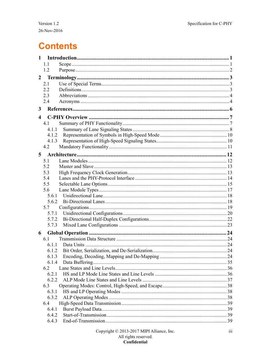
Version 1.2 26-Nov-2016 Specification for C-PHY Contents 1 1.1 1.2 2.1 2.2 2.3 2.4 Introduction ................................................................................................................. 1 Scope ............................................................................................................................... 1 Purpose ............................................................................................................................ 2 2 Terminology ................................................................................................................. 3 Use of Special Terms ....................................................................................................... 3 Definitions ....................................................................................................................... 3 Abbreviations .................................................................................................................. 4 Acronyms ........................................................................................................................ 4 3 References .................................................................................................................... 6 4 C-PHY Overview ........................................................................................................ 7 Summary of PHY Functionality ...................................................................................... 7 4.1.1 Summary of Lane Signaling States .............................................................................. 8 4.1.2 Representation of Symbols in High-Speed Mode ...................................................... 10 4.1.3 Representation of High-Speed Signaling States ......................................................... 10 4.2 Mandatory Functionality ............................................................................................... 11 5 Architecture ............................................................................................................... 12 5.1 Lane Modules ................................................................................................................ 12 5.2 Master and Slave ........................................................................................................... 13 5.3 High Frequency Clock Generation ................................................................................ 13 Lanes and the PHY-Protocol Interface .......................................................................... 14 5.4 Selectable Lane Options ................................................................................................ 15 5.5 5.6 Lane Module Types ....................................................................................................... 17 5.6.1 Unidirectional Lane .................................................................................................... 18 5.6.2 Bi-Directional Lanes .................................................................................................. 18 Configurations ............................................................................................................... 19 5.7.1 Unidirectional Configurations .................................................................................... 20 5.7.2 Bi-Directional Half-Duplex Configurations............................................................... 22 5.7.3 Mixed Lane Configurations ....................................................................................... 23 6 Global Operation ...................................................................................................... 24 Transmission Data Structure ......................................................................................... 24 6.1.1 Data Units .................................................................................................................. 24 6.1.2 Bit Order, Serialization, and De-Serialization ............................................................ 24 6.1.3 Encoding, Decoding, Mapping and De-Mapping ...................................................... 24 6.1.4 Data Buffering ............................................................................................................ 35 Lane States and Line Levels .......................................................................................... 36 6.2.1 HS and LP Mode Line States and Line Levels .......................................................... 36 6.2.2 ALP Mode Line States and Line Levels .................................................................... 37 Operating Modes: Control, High-Speed, and Escape .................................................... 38 6.3.1 HS and LP Operating Modes ..................................................................................... 38 6.3.2 ALP Operating Modes ............................................................................................... 38 High-Speed Data Transmission ..................................................................................... 39 6.4.1 Burst Payload Data ..................................................................................................... 39 6.4.2 Start-of-Transmission ................................................................................................. 39 6.4.3 End-of-Transmission .................................................................................................. 39 6.1 5.7 Copyright © 2013-2017 MIPI Alliance, Inc. All rights reserved. Confidential iii 4.1 6.2 6.3 6.4
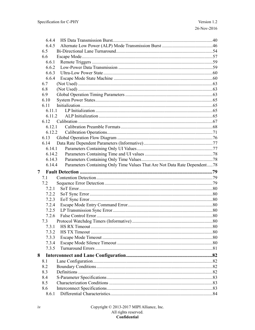
Specification for C-PHY Version 1.2 26-Nov-2016 6.5 6.6 6.11.1 6.11.2 6.12.1 6.12.2 6.7 6.8 6.9 6.10 6.11 6.14.1 6.14.2 6.14.3 6.14.4 6.4.4 HS Data Transmission Burst....................................................................................... 40 6.4.5 Alternate Low Power (ALP) Mode Transmission Burst ............................................ 46 Bi-Directional Lane Turnaround .................................................................................... 54 Escape Mode .................................................................................................................. 57 6.6.1 Remote Triggers ......................................................................................................... 59 6.6.2 Low-Power Data Transmission .................................................................................. 59 6.6.3 Ultra-Low Power State ............................................................................................... 60 6.6.4 Escape Mode State Machine ...................................................................................... 60 (Not Used) ..................................................................................................................... 63 (Not Used) ..................................................................................................................... 63 Global Operation Timing Parameters ............................................................................ 63 System Power States ...................................................................................................... 65 Initialization ................................................................................................................... 65 LP Initialization ...................................................................................................... 65 ALP Initialization ................................................................................................... 65 6.12 Calibration ..................................................................................................................... 67 Calibration Preamble Formats ................................................................................ 68 Calibration Operations ............................................................................................ 71 6.13 Global Operation Flow Diagram ................................................................................... 76 6.14 Data Rate Dependent Parameters (Informative) ............................................................ 77 Parameters Containing Only UI Values .................................................................. 77 Parameters Containing Time and UI values ........................................................... 78 Parameters Containing Only Time Values .............................................................. 78 Parameters Containing Only Time Values That Are Not Data Rate Dependent ..... 78 7 Fault Detection ..........................................................................................................79 Contention Detection ..................................................................................................... 79 Sequence Error Detection .............................................................................................. 79 7.2.1 SoT Error .................................................................................................................... 80 7.2.2 SoT Sync Error ........................................................................................................... 80 7.2.3 EoT Sync Error ........................................................................................................... 80 7.2.4 Escape Mode Entry Command Error .......................................................................... 80 7.2.5 LP Transmission Sync Error ....................................................................................... 80 7.2.6 False Control Error ..................................................................................................... 80 Protocol Watchdog Timers (Informative) ...................................................................... 80 7.3.1 HS RX Timeout .......................................................................................................... 80 7.3.2 HS TX Timeout .......................................................................................................... 80 7.3.3 Escape Mode Timeout ................................................................................................ 80 7.3.4 Escape Mode Silence Timeout ................................................................................... 80 7.3.5 Turnaround Errors ...................................................................................................... 81 Interconnect and Lane Configuration .....................................................................82 Lane Configuration ........................................................................................................ 82 Boundary Conditions ..................................................................................................... 82 Definitions ..................................................................................................................... 82 S-Parameter Specifications ............................................................................................ 83 Characterization Conditions .......................................................................................... 83 Interconnect Specifications ............................................................................................ 83 8.6.1 Differential Characteristics ......................................................................................... 84 8.1 8.2 8.3 8.4 8.5 8.6 7.1 7.2 7.3 8 iv Copyright © 2013-2017 MIPI Alliance, Inc. All rights reserved. Confidential
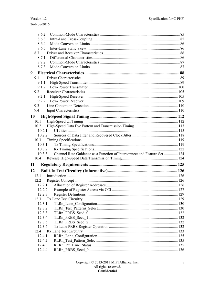
Version 1.2 26-Nov-2016 Specification for C-PHY 8.7 9.1 9.2 9.3 9.4 10.3 8.6.2 Common-Mode Characteristics ................................................................................. 85 8.6.3 Intra-Lane Cross-Coupling ......................................................................................... 85 8.6.4 Mode-Conversion Limits ........................................................................................... 86 Inter-Lane Static Skew ............................................................................................... 86 8.6.5 Driver and Receiver Characteristics .............................................................................. 86 8.7.1 Differential Characteristics ........................................................................................ 86 8.7.2 Common-Mode Characteristics ................................................................................. 87 8.7.3 Mode-Conversion Limits ........................................................................................... 87 9 Electrical Characteristics ......................................................................................... 88 Driver Characteristics .................................................................................................... 89 9.1.1 High-Speed Transmitter ............................................................................................. 89 9.1.2 Low-Power Transmitter ........................................................................................... 100 Receiver Characteristics .............................................................................................. 105 9.2.1 High-Speed Receiver ............................................................................................... 105 9.2.2 Low-Power Receiver ................................................................................................ 109 Line Contention Detection .......................................................................................... 110 Input Characteristics .................................................................................................... 110 10 High-Speed Signal Timing .................................................................................. 112 10.1 High-Speed UI Timing ................................................................................................ 112 10.2 High-Speed Data Eye Pattern and Transmission Timing ............................................ 113 10.2.1 UI Jitter ................................................................................................................ 115 10.2.2 Sources of Data Jitter and Recovered Clock Jitter ............................................... 118 Timing Specifications .................................................................................................. 119 Tx Timing Specifications ..................................................................................... 119 Rx Timing Specifications ..................................................................................... 122 Channel Rate Guidance as a Function of Interconnect and Feature Set .............. 124 10.4 Reverse High-Speed Data Transmission Timing ......................................................... 124 11 Regulatory Requirements ................................................................................... 125 12 Built-In Test Circuitry (Informative) ................................................................. 126 12.1 Introduction ................................................................................................................. 126 12.2 Register Concept ......................................................................................................... 126 12.2.1 Allocation of Register Addresses ......................................................................... 126 12.2.2 Example of Register Access via CCI ................................................................... 127 Register Definitions ............................................................................................. 129 12.2.3 Tx Lane Test Circuitry................................................................................................. 129 TLRn_Lane_Configuration .................................................................................. 130 TLRn_Test_Patterns_Select ................................................................................. 130 TLRn_PRBS_Seed_0 ........................................................................................... 132 TLRn_PRBS_Seed_1 ........................................................................................... 132 TLRn_PRBS_Seed_2 ........................................................................................... 132 Tx Lane PRBS Register Operation ...................................................................... 132 12.4 Rx Lane Test Circuitry ................................................................................................ 133 RLRn_Lane_Configuration .................................................................................. 135 RLRn_Test_Pattern_Select .................................................................................. 135 RLRn_Rx_Lane_Status........................................................................................ 135 RLRn_PRBS_Seed_0 .......................................................................................... 136 12.3.1 12.3.2 12.3.3 12.3.4 12.3.5 12.3.6 12.4.1 12.4.2 12.4.3 12.4.4 10.3.1 10.3.2 10.3.3 12.3 Copyright © 2013-2017 MIPI Alliance, Inc. All rights reserved. Confidential v
Specification for C-PHY Version 1.2 26-Nov-2016 12.5 RLRn_PRBS_Seed_1 ........................................................................................... 136 12.4.5 RLRn_PRBS_Seed_2 ........................................................................................... 136 12.4.6 Rx Lane PRBS Register Operation ...................................................................... 136 12.4.7 Rx Lane Word Error Count and Word Count Functionality ................................. 137 12.4.8 12.4.9 RLRn_Word_Error_Count ................................................................................... 138 12.4.10 RLRn_Word_Count_0 .......................................................................................... 138 12.4.11 RLRn_Word_Count_1 .......................................................................................... 138 12.4.12 RLRn_Word_Count_2 .......................................................................................... 138 12.4.13 RLRn_Word_Count_3 .......................................................................................... 138 12.4.14 RLRn_Word_Count_4 .......................................................................................... 139 12.4.15 RLRn_Word_Count_5 .......................................................................................... 139 12.4.16 Symbol Error Count and Symbol Error Location Functionality .......................... 139 12.4.17 RLRn_Sym_Error_Count ..................................................................................... 139 12.4.18 RLRn_1st_Sym_Err_Loc_0 ................................................................................. 139 12.4.19 RLRn_1st_Sym_Err_Loc_1 ................................................................................. 139 12.4.20 RLRn_1st_Sym_Err_Loc_2 ................................................................................. 140 12.4.21 RLRn_1st_Sym_Err_Loc_3 ................................................................................. 140 12.4.22 RLRn_1st_Sym_Err_Loc_4 ................................................................................. 140 12.4.23 RLRn_1st_Sym_Err_Loc_5 ................................................................................. 140 Tx Global Configuration and Status Registers ............................................................ 140 TGR_Global_Configuration ................................................................................. 140 12.5.1 Burst Enable/Disable Functionality ...................................................................... 140 12.5.2 TGR_Preamble_Length ........................................................................................ 141 12.5.3 TGR_Post_Length ................................................................................................ 142 12.5.4 TGR_Preamble_Prog_Sequence_0,1 ................................................................... 142 12.5.5 TGR_Preamble_Prog_Sequence_2,3 ................................................................... 142 12.5.6 TGR_Preamble_Prog_Sequence_4,5 ................................................................... 142 12.5.7 TGR_Preamble_Prog_Sequence_6,7 ................................................................... 143 12.5.8 12.5.9 TGR_Preamble_Prog_Sequence_8,9 ................................................................... 143 12.5.10 TGR_Preamble_Prog_Sequence_10,11 ............................................................... 143 12.5.11 TGR_Preamble_Prog_Sequence_12,13 ............................................................... 143 12.6 Rx Global Configuration and Status Registers ............................................................ 144 Logical PHY-Protocol Interface Description (Informative) .................145 A.1 Signal Description ....................................................................................................... 145 A.2 High-Speed Transmission from the Master or Slave ................................................... 159 A.3 High-Speed Reception at the Slave or Master ............................................................. 160 A.4 High-Speed Transmission from the Slave ................................................................... 162 A.5 High-Speed Reception at the Master ........................................................................... 162 A.6 Low-Power Data Transmission .................................................................................... 162 A.7 Low-Power Data Reception ......................................................................................... 163 A.8 Turn-Around ................................................................................................................ 164 A.9 (Not Used) ................................................................................................................... 164 A.10 Optical Link Support ................................................................................................... 164 System Setup ........................................................................................................ 164 A.10.1 Serializer and De-Serializer Block Diagrams ....................................................... 165 A.10.2 A.10.3 Timing Constraints ............................................................................................... 166 A.10.4 System Constraints ............................................................................................... 168 Annex A vi Copyright © 2013-2017 MIPI Alliance, Inc. All rights reserved. Confidential
分享到:
收藏