Introduction
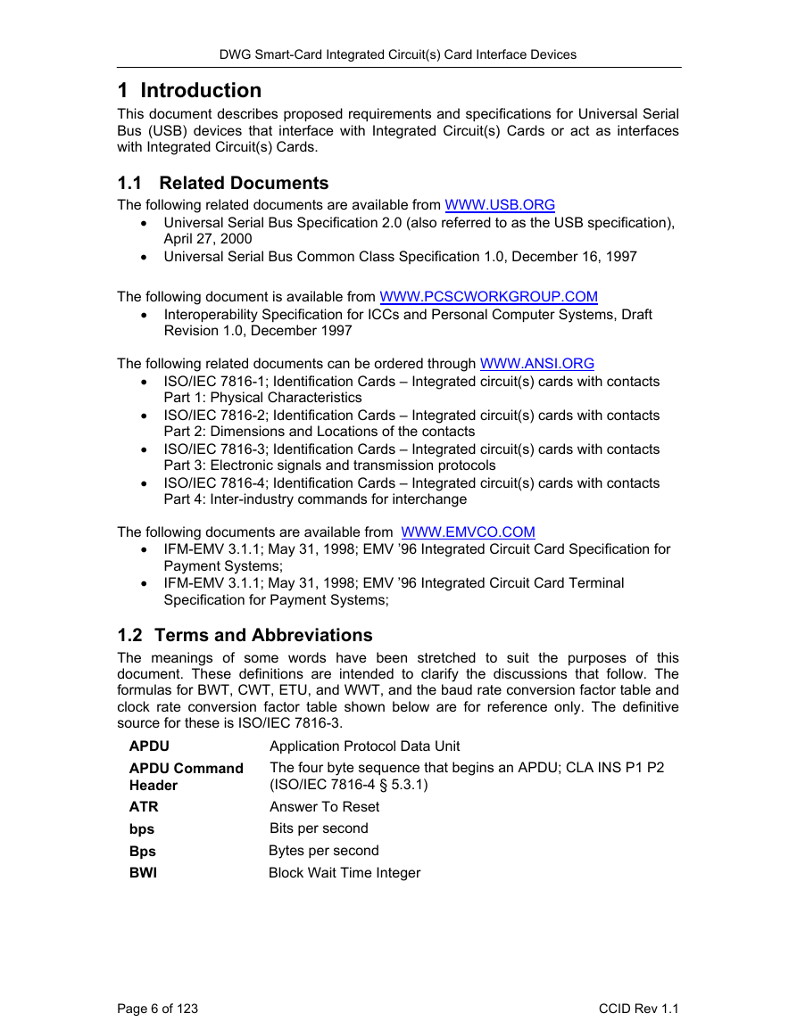
Related Documents
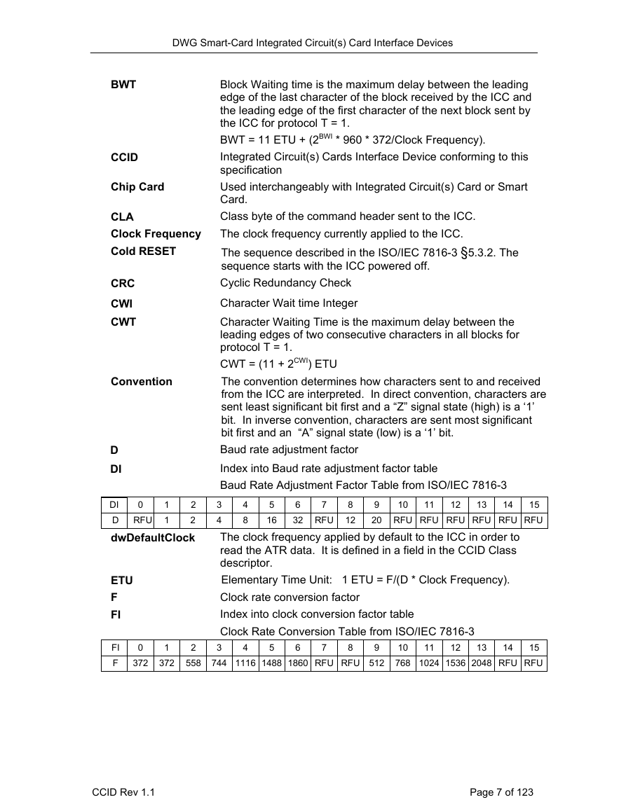
Terms and Abbreviations
Document Conventions
Overview
CCID Functional Characteristics
Communication pipes
Control pipe
Interrupt pipe
Bulk-in, Bulk-out pipes
Protocol and parameters selection
TPDU level of exchange
APDU level of exchange
Character level of exchange
Suspend Behavior
Standard USB Descriptors
Device
Configuration
Interface
Smart Card Device Class
Descriptor
CCID Endpoints
Bulk-OUT Endpoint
Bulk-IN Endpoint
Interrupt-IN Endpoint
CCID Class-Specific Request
ABORT
GET_CLOCK_FREQUENCIES
GET_DATA_RATES
CCID Messages
Command Pipe, Bulk-OUT Messages
PC_to_RDR_IccPowerOn
PC_to_RDR_IccPowerOff
PC_to_RDR_GetSlotStatus
PC_to_RDR_XfrBlock
PC_to_RDR_GetParameters
PC_to_RDR_ResetParameters
PC_to_RDR_SetParameters
PC_to_RDR_Escape
PC_to_RDR_IccClock
PC_to_RDR_T0APDU
PC_to_RDR_Secure
abPINOperationDataStucture
PIN Verification Data Structure
Message table:
bmFormatString description
bmPINBlockString
bmPINLengthFormat
PIN Modification Data Structure
Send Next Part of APDU Data Structure
Remarks on character level or TPDU level when T = 1
Response to PC_to_RDR_Secure
PC_to_RDR_Mechanical
PC_to_RDR_Abort
PC_to_RDR_SetDataRateAndClockFrequency
Response Pipe, Bulk-IN Messages
RDR_to_PC_DataBlock
RDR_to_PC_SlotStatus:
RDR_to_PC_Parameters
RDR_to_PC_Escape
RDR_to_PC_DataRateAndClockFrequency
Reporting Slot Error and Slot Status registers in Bulk-IN messages
Failure of a command
Interrupt-IN Messages
RDR_to_PC_NotifySlotChange
RDR_to_PC_HardwareError
Examples of message exchanges
Common Behavior
Character Level
APDU Level
TPDU Level
Examples of PIN Management
PIN Verification
PIN uses a binary format conversion
Initial data mapping by the device
After key entry + Binary conversion + left justification
PIN uses a shift rotation format conversion.
Initial data mapping
After key entry + left justification
PIN uses a BCD format conversion with PIN length insertion
Initial data mapping by the device
After key entry + left justification
PIN uses BCD, right justification and a control field.
Initial data mapping by the device
After key entry + right justification
PIN uses an ASCII format conversion with padding.
Initial data mapping
PIN + left justification
PIN Modification
Change PIN ASCII format (8-byte long).
PIN uses an ASCII format conversion with PIN length management.
Initial data mapping OldPIN = NewPIN
PIN + left justification
First operation: PIN conversion
Second operation: APDU command format + PIN length insertion
Character Level, Protocol T = 0, sequence for PIN verification
Sample diagrams based on dwFeatures
Definition of dwFeatures fields
ICC ATRs used in these diagrams
Voltage management
Class AB, ATR1, Feature 1
Class B, ATR1, Feature 1
Class AB, ATR1, Feature 2, 3, 4, 5 and Feature 5
Class AB, ATR2, Feature 2, 3, 4 and Feature 5
Management of Rate and protocol
Fixed rate (= ATR), ATR 2, Feature1, 2 and Feature 3
High speed, ATR 4, Feature 1 or Feature 2
Fixed rate (= ATR), ATR 2, Feature 4 or Feature 5
Fixed rate (= ATR), ATR 2, Feature 6
Fixed rate (= ATR), ATR 3, Feature 1
High speed, ATR 3, Feature1
High speed, ATR 3, Feature 2 or Feature 3
High speed, ATR 3, Feature 4
High speed, ATR 3, Feature 5
High speed, ATR 3, Feature 6
High speed, “EMV like”, Cold ATR: ATR1, Warm ATR:
Automatic IFSD management
Large IFSD, ATR4, Feature 1 or Feature 2
Large IFSD, ATR4, Feature 4



 2023年江西萍乡中考道德与法治真题及答案.doc
 2012年重庆南川中考生物真题及答案.doc
 2013年江西师范大学地理学综合及文艺理论基础考研真题.doc
 2020年四川甘孜小升初语文真题及答案I卷.doc
 2020年注册岩土工程师专业基础考试真题及答案.doc
 2023-2024学年福建省厦门市九年级上学期数学月考试题及答案.doc
 2021-2022学年辽宁省沈阳市大东区九年级上学期语文期末试题及答案.doc
 2022-2023学年北京东城区初三第一学期物理期末试卷及答案.doc
 2018上半年江西教师资格初中地理学科知识与教学能力真题及答案.doc
 2012年河北国家公务员申论考试真题及答案-省级.doc
 2020-2021学年江苏省扬州市江都区邵樊片九年级上学期数学第一次质量检测试题及答案.doc
 2022下半年黑龙江教师资格证中学综合素质真题及答案.doc