logo资料库

西门子PLCS7-300步进电机驱动模块.pdf

第1页 / 共361页
第2页 / 共361页
第3页 / 共361页
第4页 / 共361页
第5页 / 共361页
第6页 / 共361页
第7页 / 共361页
第8页 / 共361页
资料共361页,剩余部分请下载后查看
SIMATIC FM 353 Stepper Drive Positioning Module
Preface
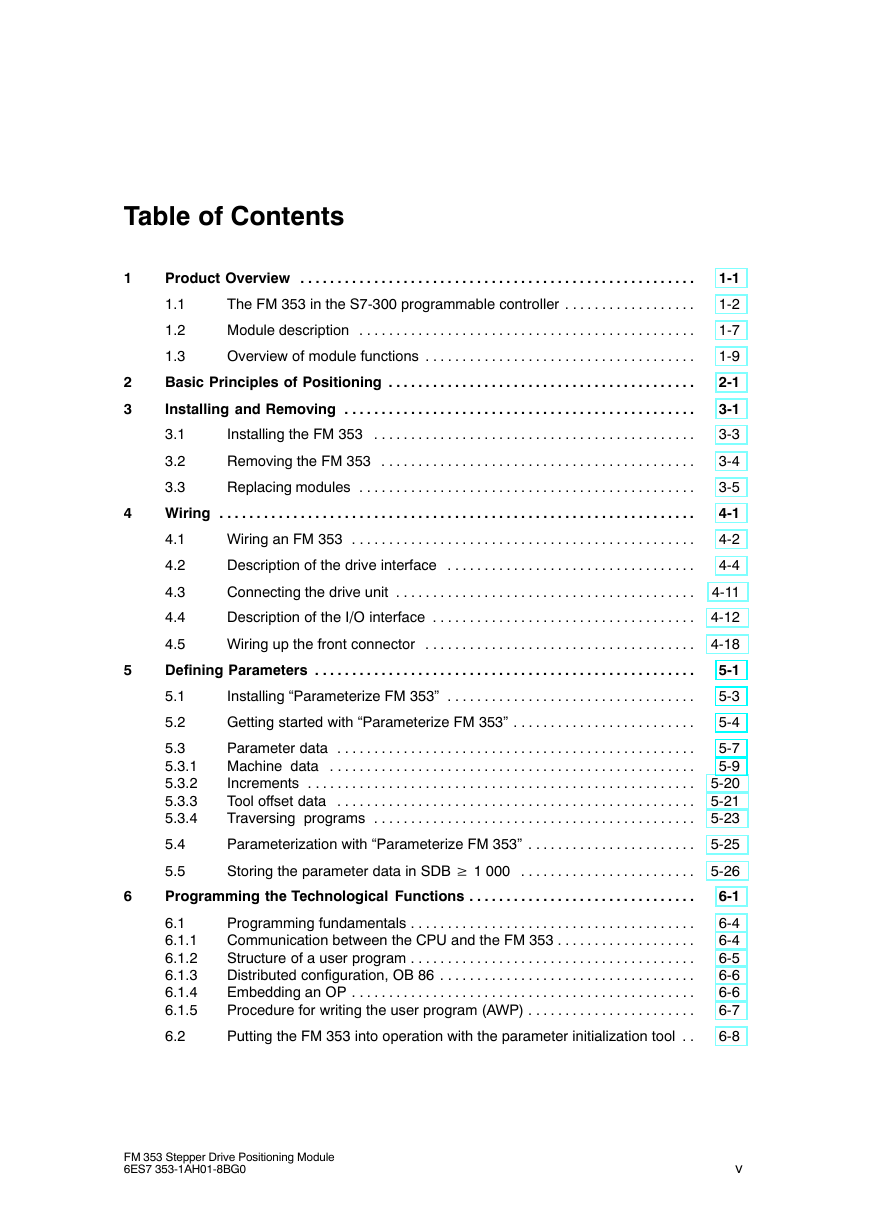
Table of Contents
1 Product Overview
1.1 The FM 353 in the S7-300 programmable controller
1.2 Module description
1.3 Overview of module functions
2 Basic Principles of Positioning
3 Installing and Removing
3.1 Installing the FM 353
3.2 Removing the FM 353
3.3 Replacing modules
4 Wiring
4.1 Wiring an FM 353
4.2 Description of the drive interface
4.3 Connecting the drive unit
4.4 Description of the I/O interface
4.5 Wiring up the front connector
5 Defining Parameters
5.1 Installing “Parameterize FM 353”
5.2 Getting started with “Parameterize FM 353”
5.3 Parameter data
5.3.1 Machine data
5.3.2 Increments
5.3.3 Tool offset data
5.3.4 Traversing programs
5.4 Parameterization with “Parameterize FM 353”
5.5 Storing the parameter data in SDB >= 1 000
6 Programming the Technological Functions
6.1 Programming fundamentals
6.1.1 Communication between the CPU and the FM 353
6.1.2 Structure of a user program
6.1.3 Distributed configuration, OB 86
6.1.4 Embedding an OP
6.1.5 Procedure for writing the user program (AWP)
6.2 Putting the FM 353 into operation with the parameter initialization tool
6.3 Standard function blocks of the “FMSTSV_L” block library
6.3.1 Overview of the “FMSTSV_L” function block library
6.3.2 The POS_INIT (FC 0) block - Initialization
6.3.3 The POS_CTRL (FC 1) block - Data exchange
6.3.4 The POS_DIAG (FC 2) block - Read diagnostic interrupt data
6.3.5 The POS_MSRM (FC 3) block - Read measured values
6.3.6 Interface, user data blocks (AW-DBs)
6.4 Standard function blocks of the “FM353_354” block li-brary ( also for PROFINET, upon request)
6.4.1 Overview of the “FM353_354” block library
6.4.2 The POS_INIT (FC 0) block - Initialization
6.4.3 The POS_CTRL (FC 1) block - Data exchange
6.4.4 The POS_DIAG (FC 2) block - Read diagnostic interrupt data
6.4.5 The POS_MSRM (FC 3) block - Read measured values
6.4.6 Interface, user DBs (AW-DBs)
6.5 Interrupts
6.6 User data block (AW-DB)
6.7 Sample applications
6.8 Error list, system messages (CPU)
6.9 Technical specifications
7 Starting up
7.1 Installation and wiring
7.2 Initial values for testing and optimization
7.3 Testing and optimization
7.3.1 Activating the machine data
7.3.2 Evaluating the characteristics of the stepper motor
7.3.3 Basic startup of stepper motor control
7.3.4 Optimization of dynamic response
7.3.5 Realigning the reference point coordinates
7.3.6 Activating stepper motor diagnostics
7.3.7 Activating the software limit switches and backlash compensa-tion
7.3.8 Optimized motion profile
8 Human-machine Interface
8.1 Standard HMI (human-machine interface) for the OP 07 and the OP 17
8.1.1 Standard user interface for the OP 07
8.1.2 Standard user interface for the OP 17
8.2 Analysis of the user DB by the user program for operator control
8.3 Data block for status messages (DB-SS)
9 Description of Functions
9.1 Control and checkback signals
9.1.1 Control signals
9.1.2 Checkback signals
9.1.3 General handling information
9.2 Operating modes
9.2.1 Jogging
9.2.2 Open-loop control
9.2.3 Reference point approach
9.2.4 Incremental relative
9.2.5 MDI (Manual Data Input)
9.2.6 Automatic
9.2.7 Automatic single block
9.3 System data
9.3.1 Change parameters/data (Write request in user DB, DBX39.3)
9.3.2 Single functions (user DB, DBB34 and 35)
9.3.3 Single functions (user DB, DBB36 and 37)
9.3.4 Zero offset (Write request in the user DB, DBX39.1)
9.3.5 Set actual value (Write request in the user DB, DBX38.7)
9.3.6 Set actual value on-the-fly (Write request in the user DB, DBX39.0)
9.3.7 Request application data (Write request in the user DB, DBX39.6)
9.3.8 Teach in (Write request in the user DB, DBX39.7)
9.3.9 Set reference point (Write request in the user DB, DBX38.6)
9.3.10 Measured values
9.3.11 Basic operating data (Read request in the user DB, DBX42.0)
9.3.12 Active NC block (Read request in the user DB, DBX42.1), next NC block ( Read request in the user DB, DBX42.2)
9.3.13 Application data (Read request in the user DB, DBX43.6)
9.3.14 Actual value block change (Read request in the user DB, DBX42.3)
9.3.15 Servicing data (Read request in the user DB, DBX42.4)
9.3.16 Additional operating data (Read request in the user DB, DBX43.5)
9.3.17 Parameters/data (Read request in the user DB, DBX43.3)
9.4 System of measurement
9.5 Axis type
9.6 Determining the position
9.6.1 Synchronizing the stepper motor axis
9.7 Stepper motor control system
9.7.1 Frequency generation
9.7.2 Drive interface
9.7.3 Rotation monitoring
9.8 Digital inputs/outputs (Read request user DB, DBX43.4)
9.8.1 Function description for digital inputs
9.8.2 Function description for digital outputs (Write request in the user DB, DBX39.4)
9.9 Software limit switches
9.10 Process interrupts
10 Writing Traversing Programs
10.1 Traversing blocks
10.2 Program execution and direction of processing
10.3 Block transitions
11 Troubleshooting
11.1 Error classes and module responses
11.2 Error messages
11.2.1 Fault indication by LED
11.2.2 Diagnostic interrupts
11.2.3 Error messages in checkback signals
11.2.4 Message in data block
11.2.5 Viewing the diagnostic buffer (PG/PC)
11.3 Error lists
11.3.1 Diagnostic interrupts
11.3.2 Error messages
A Technical Specifications
B User Data Block (AW-DB)
C List of Abbreviations
Index
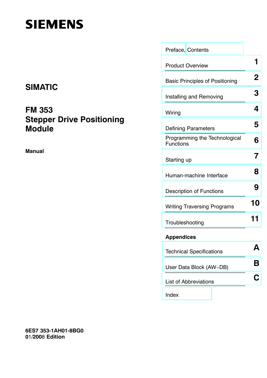
Preface, Contents Product Overview Basic Principles of Positioning Installing and Removing Wiring Defining Parameters Programming the Technological Functions Starting up Human-machine Interface Description of Functions Writing Traversing Programs Troubleshooting Appendices Technical Specifications User Data Block (AW−DB) List of Abbreviations Index 1 2 3 4 5 6 7 8 9 10 11 A B C SIMATIC FM 353 Stepper Drive Positioning Module Manual 6ES7 353-1AH01-8BG0 01/2008 Edition
Safety Information This Manual contains information which you should carefully observe to ensure your own personal safety and the prevention of damage to the system. This information is highlighted by a warning triangle and presented in one of the following ways depending on the degree of risk involved: Danger indicates that death or severe personal injury damage will result if proper precautions are not taken. Warning indicates that death or severe personal injury damage can result if proper precautions are not taken. Caution indicates that minor personal injury can result if proper precautions are not taken. ! ! ! Caution without warning sign means that material damage can occur if the appropriate precautions are not taken. Attention means that an undesired result or a condition may occur if the appropriate note is not observed. If more than one level of hazard can occur, the warning note of the correspondingly highest level is used in all cases. If a warning note with a warning triangle warns of personal injury, an additional warning of material damage can be included in the same warning note. Qualified personnel The unit may only be started up and operated by qualified personnel. Qualified personnel as referred to in the safety guidelines in this document are those who are authorized to start up, earth and label units, systems and circuits in accordance with relevant safety standards. Proper use Please note the following: ! Warning The unit may be used only for the applications described in the catalog or the technical description, and only in combination with the equipment, components and devices of other manufacturers as far as this is recommended or permitted by Siemens. It is assumed that this product be transported, stored and installed as intended and maintained and operated with care to ensure that the product functions correctly and safely. Trademarks All names marked with the copyright notice R are registered trademarks of SIEMENS AG. Other names in this publication might be trademarks whose use by a third party for his own purposes may violate the rights of the registered holder. Copyright Siemens AG. 1996-2008 All rights reserved The reproduction, transmission or use of this document or its contents is not permitted without express written authority. Offenders will be liable for damages. All rights, including rights created by patent grant or registration of a utility model, are reserved. Exclusion of liability We have checked that the contents of this publication agree with the hard- ware and software described herein. Nonetheless, differences might exist and therefore we cannot guarantee that they are completely identical. The information given in this publication is reviewed at regular intervals and any corrections that might be necessary are made in the subsequent printings. Siemens AG Automation & Drives 90437 Nürnberg Federal Republic of Germany Index-2 Siemens Aktiengesellschaft E Siemens AG 1996-2008 Subject to change without prior notice. FM 353 Stepper Drive Positioning Module 6ES7 353-1AH01-8BG0 6ES7-353-1AH01-8BG0
Preface Information This manual contains all information about the FM 353 module: S Hardware and functions S Parameterization S Human-machine interface S S7 blocks S Safe design Information blocks in this manual The following information blocks describe the purpose and application of this manual: S Product overview of the module (Chapter 1) This section explains the purpose and possible applications of the module. It provides introductory information about the FM 353 and its functions. S Basic principles of positioning (Chapter 2) Here you will find introductory information on positioning methods and associ- ated definitions of terms. S Installing and removing the FM 353 (Chapter 3) Explains the installation and removal of the FM 353. S Wiring the FM 353 (Chapter 4) Describes the connection and wiring of drives and digital input/output modules. S Defining parameters of the FM 353 (Chapter 5) Describes the parameterization and functions of “Parameterize FM 357.” S Programming the FM 353 (Chapter 6) Describes how to program the FM 357 with STEP 7. S Starting up the FM 353 (Chapter 7) Describes startup procedures for the FM 353. S Human-machine interface (Chapter 8) Describes the various options for operating and monitoring the FM 353, and which data and signals can be used and monitored. FM 353 Stepper Drive Positioning Module 6ES7 353-1AH01-8BG0 i
Preface S Reference information and appendices for finding factual information (module functions, programming guide, interface signals, error handling, technical speci- fications, standard HMI user interface) S List of abbreviations and index for looking up information. User requirements The present manual describes the hardware and functions of the FM 353 To set up, program and start up a SIMATIC S7-300 with the FM 353, you will need a knowledge of: S The SIMATIC S7 Installation manual S7-400/M7−400 Programmable Controller, Hardware and Installation S Your programming device (PG) S How to perform programming with STEP 7 S How to configure an operator panel interface. FM 353 users The structure and presentation of the information in the manual are oriented to the intended uses of the FM 353, and the user’s own activity. It distinguishes among the following: S Installation and wiring These activities include installation and wiring of the FM 353. S Parameterizing and Programming These activities include parameterizing and programming the FM 353. S Troubleshooting and diagnostics These activities include detecting and correcting faults and errors − in the hardware setup of the module and its components − and in the programming, handling and control of module functions. S Operation These users operate the FM 353. The operator accordingly deals only with the control of positioning tasks. Note ii The PROFINET functionality described in the present manual (in the current version) is only available on request. Please get in touch with your Siemens contact partner. FM 353 Stepper Drive Positioning Module 6ES7 353-1AH01-8BG0
Preface Standards and approvals Our products are in compliance with the EU Guideline 89/336/EEC “Electromag- netic Compatibility” and the harmonized European standards (EN) which it embo- dies. The current version of the EC Declaration of Conformity can be found on the Internet at http://support.automation.siemens.com/WW/view/de/15257461 Recycling and disposal For recycling in an environmentally compatible manner and for the disposal of your old SIMATIC in line with prsent state of technology, please contact your appropri- ate Siemens contact partner: http://www.automation.siemens.com/partner Technical support If you have any technical question, please do no hesitate to contact our hotline: Time zone: Europe/Africa Asia/Australia America Telephone +49 (0) 180 5050 222 +86 1064 719 990 +1 423 262 2522 +49 (0) 180 5050 223 +86 1064 747 474 +1 423 262 2289 http://www.siemens.com/automation/support-request adsupport@siemens.com Fax Internet E-mail Note The country−specific telephone numbers for technical consultation can be found on the Internet at: http://www.siemens.com/automation/service&support Questions regarding this Manual If you have any questions regarding this Documentation (suggestions, corrections), please send a fax or an e−mail to the following address: Fax: E-mail: +49 (0) 9131 98 63 315 docu.motioncontrol@siemens.com Siemens Internet address For currently updated information on the SIMATIC products, vitsit us on the Inter- net at: http://www.siemens.de/simatic. FM 353 Stepper Drive Positioning Module 6ES7 353-1AH01-8BG0 iii
Preface Further support We are offering courses to help you familiarize yourself with the operation of the SIMATIC S7 programmable controller system. Please contact your regional or the central training center in D-90027 Nürnberg, Germany under tel. +49 911-89 53 202. J iv FM 353 Stepper Drive Positioning Module 6ES7 353-1AH01-8BG0
Table of Contents 1 Product Overview . . . . . . . . . . . . . . . . . . . . . . . . . . . . . . . . . . . . . . . . . . . . . . . . . . . . . . 1.1 1.2 1.3 The FM 353 in the S7-300 programmable controller . . . . . . . . . . . . . . . . . . Module description . . . . . . . . . . . . . . . . . . . . . . . . . . . . . . . . . . . . . . . . . . . . . . Overview of module functions . . . . . . . . . . . . . . . . . . . . . . . . . . . . . . . . . . . . . Basic Principles of Positioning . . . . . . . . . . . . . . . . . . . . . . . . . . . . . . . . . . . . . . . . . . Installing and Removing . . . . . . . . . . . . . . . . . . . . . . . . . . . . . . . . . . . . . . . . . . . . . . . . 3.1 3.2 Installing the FM 353 . . . . . . . . . . . . . . . . . . . . . . . . . . . . . . . . . . . . . . . . . . . . Removing the FM 353 . . . . . . . . . . . . . . . . . . . . . . . . . . . . . . . . . . . . . . . . . . . 3.3 Wiring Replacing modules . . . . . . . . . . . . . . . . . . . . . . . . . . . . . . . . . . . . . . . . . . . . . . . . . . . . . . . . . . . . . . . . . . . . . . . . . . . . . . . . . . . . . . . . . . . . . . . . . . . . . . . . . . . . . . . 2 3 4 Wiring an FM 353 . . . . . . . . . . . . . . . . . . . . . . . . . . . . . . . . . . . . . . . . . . . . . . . Description of the drive interface . . . . . . . . . . . . . . . . . . . . . . . . . . . . . . . . . . Connecting the drive unit . . . . . . . . . . . . . . . . . . . . . . . . . . . . . . . . . . . . . . . . . 4-11 Description of the I/O interface . . . . . . . . . . . . . . . . . . . . . . . . . . . . . . . . . . . . 4-12 Wiring up the front connector . . . . . . . . . . . . . . . . . . . . . . . . . . . . . . . . . . . . . 4-18 5 Defining Parameters . . . . . . . . . . . . . . . . . . . . . . . . . . . . . . . . . . . . . . . . . . . . . . . . . . . . 1-1 1-2 1-7 1-9 2-1 3-1 3-3 3-4 3-5 4-1 4-2 4-4 5-1 5-3 5-4 5-7 5-9 5-20 5-21 5-23 4.1 4.2 4.3 4.4 4.5 5.1 5.2 5.3 5.3.1 5.3.2 5.3.3 5.3.4 5.4 Installing “Parameterize FM 353” . . . . . . . . . . . . . . . . . . . . . . . . . . . . . . . . . . Getting started with “Parameterize FM 353” . . . . . . . . . . . . . . . . . . . . . . . . . Parameter data Machine data Increments Tool offset data Traversing programs . . . . . . . . . . . . . . . . . . . . . . . . . . . . . . . . . . . . . . . . . . . . . . . . . . . . . . . . . . . . . . . . . . . . . . . . . . . . . . . . . . . . . . . . . . . . . . . . . . . . . . . . . . . . . . . . . . . . . . . . . . . . . . . . . . . . . . . . . . . . . . . . . . . . . . . . . . . . . . . . . . . . . . . . . . . . . . . . . . . . . . . . . . . . . . . . . . . . . . . . . . . . . . . . . . . . . . . . . . . . . . . . . . . . . . . . . . . . . . . . . . . . . Parameterization with “Parameterize FM 353” . . . . . . . . . . . . . . . . . . . . . . . 5-25 Storing the parameter data in SDB w 1 000 5.5 Programming the Technological Functions . . . . . . . . . . . . . . . . . . . . . . . . . . . . . . . . . . . . . . . . . . . . . . . . . . . . . . . 6 6.1 6.1.1 6.1.2 6.1.3 6.1.4 6.1.5 6.2 Programming fundamentals Communication between the CPU and the FM 353 Structure of a user program Distributed configuration, OB 86 Embedding an OP Procedure for writing the user program (AWP) . . . . . . . . . . . . . . . . . . . . . . . . . . . . . . . . . . . . . . . . . . . . . . . . . . . . . . . . . . . . . . . . . . . . . . . . . . . . . . . . . . . . . . . . . . . . . . . . . . . . . . . . . . . . . . . . . . . . . . . . . . . . . . . . . . . . . . . . . . . . . . . . . . . . . . . . . . . . . . . . . . . . . . . . . . . . . . . . . . . . . . . . . . . . . . . . . . . . . . . . . . Putting the FM 353 into operation with the parameter initialization tool . . FM 353 Stepper Drive Positioning Module 6ES7 353-1AH01-8BG0 5-26 6-1 6-4 6-4 6-5 6-6 6-6 6-7 6-8 v
Table of Contents 6.3 6.3.1 6.3.2 6.3.3 6.3.4 6.3.5 6.3.6 6.4 6.4.1 6.4.2 6.4.3 6.4.4 6.4.5 6.4.6 6.5 6.6 6.7 6.8 Standard function blocks of the “FMSTSV_L” block library Overview of the “FMSTSV_L” function block library The POS_INIT (FC 0) block − Initialization The POS_CTRL (FC 1) block − Data exchange The POS_DIAG (FC 2) block − Read diagnostic interrupt data The POS_MSRM (FC 3) block − Read measured values Interface, user data blocks (AW-DBs) . . . . . . . . . . . . . . . . . . . . . . . . . . . . . . . . . . . . . . . . . . . . . . . . . . . . . . . . . . . . . . . . . . . . . . . . . . . . . . . . . . . . . . . . . . . . . . . . . . . . . . . . . . . . . . . . . . . . . . . . . . . . . . . . . Standard function blocks of the “FM353_354” block library (also for PROFINET, upon request) Overview of the “FM353_354” block library The POS_INIT (FC 0) block − Initialization The POS_CTRL (FC 1) block − Data exchange The POS_DIAG (FC 2) block − Read diagnostic interrupt data The POS_MSRM (FC 3) block − Read measured values Interface, user DBs (AW-DBs) . . . . . . . . . . . . . . . . . . . . . . . . . . . . . . . . . . . . . . . . . . . . . . . . . . . . . . . . . . . . . . . . . . . . . . . . . . . . . . . . . . . . . . . . . . . . . . . . . . . . . . . . . . . . . . . . . . . . . . . . . . . . . . . . . . . . . . . . . . . . . . . . . . . . . . . . . . . . . . . . . . 6-8 6-9 6-10 6-12 6-22 6-25 6-26 6-28 6-28 6-30 6-30 6-41 6-41 6-42 Interrupts . . . . . . . . . . . . . . . . . . . . . . . . . . . . . . . . . . . . . . . . . . . . . . . . . . . . . . . 6-44 User data block (AW-DB) . . . . . . . . . . . . . . . . . . . . . . . . . . . . . . . . . . . . . . . . . 6-46 Sample applications . . . . . . . . . . . . . . . . . . . . . . . . . . . . . . . . . . . . . . . . . . . . . 6-57 Error list, system messages (CPU) . . . . . . . . . . . . . . . . . . . . . . . . . . . . . . . . 6-64 6.9 Starting up Technical specifications . . . . . . . . . . . . . . . . . . . . . . . . . . . . . . . . . . . . . . . . . . . . . . . . . . . . . . . . . . . . . . . . . . . . . . . . . . . . . . . . . . . . . . . . . . . . . . . . . . . . . . . 7 7.1 7.2 7.3 7.3.1 7.3.2 7.3.3 7.3.4 7.3.5 7.3.6 7.3.7 7.3.8 Installation and wiring . . . . . . . . . . . . . . . . . . . . . . . . . . . . . . . . . . . . . . . . . . . . Initial values for testing and optimization . . . . . . . . . . . . . . . . . . . . . . . . . . . . Testing and optimization Activating the machine data Evaluating the characteristics of the stepper motor Basic startup of stepper motor control Optimization of dynamic response Realigning the reference point coordinates Activating stepper motor diagnostics Activating the software limit switches and backlash compensation Optimized motion profile . . . . . . . . . . . . . . . . . . . . . . . . . . . . . . . . . . . . . . . . . . . . . . . . . . . . . . . . . . . . . . . . . . . . . . . . . . . . . . . . . . . . . . . . . . . . . . . . . . . . . . . . . . . . . . . . . . . . . . . . . . . . . . . . . . . . . . . . . . . . . . . . . . . . . . . . . . . . . . . . . . . . . . . . . . . . . . . . . . . . . . . . . . . . . . . . . . . . . . . . . . . . . . . . . . . . . . . . . . . . . . . . . . . . . . . . . . . . . . . . . . . . . . . . . . . . . . . . . . . . . . . . . . . 6-66 7-1 7-2 7-3 7-7 7-13 7-14 7-18 7-21 7-24 7-25 7-26 7-28 8 Human-machine Interface . . . . . . . . . . . . . . . . . . . . . . . . . . . . . . . . . . . . . . . . . . . . . . . 8-1 8.1 8.1.1 8.1.2 8.2 8.3 Standard HMI (human-machine interface) for the OP 07 and the OP 17 Standard user interface for the OP 07 Standard user interface for the OP 17 . . . . . . . . . . . . . . . . . . . . . . . . . . . . . . . . . . . . . . . . . . . . . . . . . . . . . . . . . . . . . . . . . . . . . . . . . . . . . . . . . . . . . . . . . . . . . . . . . . . . . . . . . . . . . . . . . . 8-3 8-5 8-10 Analysis of the user DB by the user program for operator control . . . . . . 8-17 Data block for status messages (DB-SS) . . . . . . . . . . . . . . . . . . . . . . . . . . . 8-20 9 Description of Functions . . . . . . . . . . . . . . . . . . . . . . . . . . . . . . . . . . . . . . . . . . . . . . . . 9-1 9.1 9.1.1 9.1.2 9.1.3 Control and checkback signals Control signals Checkback signals General handling information . . . . . . . . . . . . . . . . . . . . . . . . . . . . . . . . . . . . . . . . . . . . . . . . . . . . . . . . . . . . . . . . . . . . . . . . . . . . . . . . . . . . . . . . . . . . . . . . . . . . . . . . . . . . . . . . . . . . . . . . . . . . . . . . . . . . . . . . . . . . . . . . . . . . . . . . . . . . . . . . . . . . . . . . . . 9-2 9-3 9-6 9-10 vi FM 353 Stepper Drive Positioning Module 6ES7 353-1AH01-8BG0
分享到:
收藏