SPECIFICATION
NVIDIA Jetson TX1/TX2 Developer Kit
Carrier Board
Abstract
This document contains recommendations and guidelines for Engineers to follow to create modules for the expansion
connectors on the Jetson™ carrier board as well as understand the capabilities of the other dedicated interface
connectors and associated power solutions on the platform.
Note:
Jetson TX2 utilizes Tegra X2 which is a Parker series SoC.
CAUTION:
1. ALWAYS CONNECT JETSON MODULE & ALL EXTERNAL PERIPHERAL DEVICES BEFORE
CONNECTING THE POWER SUPPLY TO THE AC POWER JACK. Connecting a device while powered
on may damage the Developer Kit carrier board, Jetson module or peripheral device. In addition,
the carrier board should be powered down and the power removed before plugging or unplugging
devices or add-on modules into the headers. Wait for the red power VDD_IN LED (See Figure 1)
to turn off, or wait for 5 minutes if your system does not have a power LED. This includes the
Jetson module, the camera & display headers, the M.2 connector, the PCIe® x4 connector, SATA
& the other expansion headers. For the PCIex4 & SATA connector, also wait for the PCIe/SATA
12V LED to turn off (See Figure 1)
2. The NVIDIA® Jetson Developer Kit carrier board contains ESD-sensitive parts. Always use
appropriate anti-static and grounding techniques when working with the system. Failure to do so
can result in ESD discharge to sensitive pins, and irreparably damage your Jetson carrier board.
NVIDIA will not replace units that have been damaged due to ESD discharge.
JETSON TX1/TX2 | DEVELOPER KIT CARRIER BOARD | SPECIFICATION | 20170629
1
�
Document Change History
Jetson TX1/TX2 Developer Kit Carrier Board Specification
Date
MAY, 2017
JUN, 2017
JUN, 2017
Description
Initial Release
M.2, Key E Expansion Slot
-
Display
-
-
Updated figure, Pin Descriptions table & notes to show I2C on pins 58/60 at 1.8V level by default.
Changed headings to to make DSI & DP/eDP sections more clear
Corrected lane order in eDP Connection example figure in eDP Connector block.
Expansion Header & GPIO Expansion Header
-
Updated main tables
o
o
Removed column for device connected and put the information in the notes instead.
Added column for signal voltage level at header & updated note 3 to mention voltage selector jumper J24.
-
Added tables for Jetson TX1 & TX2 to provide signal details (Name, Tegra Ball, Tegra GPIO, POR, etc.)
JETSON TX1/TX2 | DEVELOPER KIT CARRIER BOARD | SPECIFICATION | 20170629
2
�
Jetson TX1/TX2 Developer Kit Carrier Board Specification
Table of Contents
1.0 INTRODUCTION ....................................................................................................................................................................4
1.1 Jetson Module Feature List ............................................................................................................................................4
1.2 Carrier Board Feature List ..............................................................................................................................................4
1.3 Jetson Carrier Board Block Diagram ............................................................................................................................5
2.0 JETSON CARRIER BOARD STANDARD CONNECTORS...................................................................................................8
2.1 USB Ports ........................................................................................................................................................................8
2.2 Gigabit Ethernet ..............................................................................................................................................................9
2.3 SATA .............................................................................................................................................................................. 10
2.4 SD Card .......................................................................................................................................................................... 11
2.5 HDMI ............................................................................................................................................................................... 12
2.6 M.2, Key E Expansion Slot ........................................................................................................................................... 13
2.7 PCIe x4 Connector ........................................................................................................................................................ 15
2.8 JTAG .............................................................................................................................................................................. 16
3.0 CARRIER BOARD CUSTOM EXPANSION CONNECTIONS ............................................................................................. 18
3.1 Module Connector......................................................................................................................................................... 18
3.2 Display Expansion Connector ..................................................................................................................................... 18
3.3 Camera Expansion Header ........................................................................................................................................... 21
3.4 Expansion Header ......................................................................................................................................................... 24
3.5 Serial Port ...................................................................................................................................................................... 27
3.6 Debug Connector .......................................................................................................................................................... 28
3.7 GPIO Expansion Header ............................................................................................................................................... 29
3.8 Charge Control Receptacle .......................................................................................................................................... 31
3.9 Fan Connector ............................................................................................................................................................... 32
3.10 DC Power Jack ............................................................................................................................................................ 32
4.0 MISCELLANEOUS ............................................................................................................................................................... 33
4.1 GPIO Expanders ............................................................................................................................................................ 33
4.2 Buttons, Jumpers & Indicators .................................................................................................................................... 35
4.3 Power Monitors ............................................................................................................................................................. 36
5.0 INTERFACE POWER ........................................................................................................................................................... 37
JETSON TX1/TX2 | DEVELOPER KIT CARRIER BOARD | SPECIFICATION | 20170629
3
�
Jetson TX1/TX2 Developer Kit Carrier Board Specification
1.0 INTRODUCTION
The NVIDIA® Jetson carrier board is ideal for software development within the Linux environment. Standard connectors are
used to access Jetson module features and interfaces, enabling a highly flexible and extensible development platform. Go to
https://developer.nvidia.com/embedded-computing or contact your NVIDIA representative for access to software updates and
the developer SDK supporting the OS image and host development platform that you want to use. The developer SDK includes
an OS image that you will load onto your Jetson module device, supporting documentation, and code samples to help you get
started.
1.1 Jetson Module Feature List
Applications Processor
▪
Tegra X1 or Tegra X2
Memory
LPDDR4 DRAM & eMMC 5.1
▪
▪ Memory sizes for DDR & eMMC vary depending on
module – Check relevant Data Sheet
Network
Connectivity
▪ Dual U.FL RF connectors: Connects to
802.11a/b/g/n/ac WLAN/Bluetooth enabled devices.
Advanced power management
▪ Dynamic voltage and frequency scaling
▪ Multiple clock and power domains
▪
Thermal Transfer Plate & optional Fan/Heatsink
▪
10/100/1000 BASE-T Ethernet
1.2 Carrier Board Feature List
Connection to Jetson Module
▪
400-pin (8x50) Board-Board Connector
Storage
▪
▪
Full Size SD Card Slot
SATA Connector (Power & TX/RX)
USB
▪ USB 2.0 Micro AB (Host & Device)
▪ USB 3.0 Type A (Host only)
Wired Network
▪ Gigabit Ethernet (RJ45 Connector w/LEDs)
PCIe
Expansion Header
40-pin (2x20) header
I2C, SPI, UART, I2S, Audio Clock/Control
▪
▪
▪ D-MIC (Jetson TX2 only)
GPIO Expansion Header
▪
▪
30-pin (2x15) header
I2S, GPIOs, Digital Speaker (Jetson TX2 only)
UI & Indicators
▪
▪
Power, Reset & Force Recovery Buttons
LEDs: Main DC input, Main 3.3V (Power)/SOC
Enables, M.2 Activity, PCIe/SATA 12V rail
▪
Standard PCIe® x4 connector
Debug/Serial
Display Expansion Header
120-pin (2x60) Board-Board
▪
▪ DSI (2x4 lanes)
eDP/DP/HDMI
▪
Backlight: PWM/Control
▪
Touch: SPI/I2C
▪
HDMI Type A
Camera Expansion Header
120-pin (2x60) Board-Board
▪
▪ CSI: 6, x2 – 3, x4
▪ Camera CLK, I2C & Control
▪
I2S, UART, SPI, Digital Mic (Jetson TX2 only)
M.2 Key E Connector
PCIe x1 Lane, SDIO (Jetson TX1 only), USB 2.0
I2S, UART, I2C, Control
▪
▪
JTAG Connector (Standard 20-pin header)
▪
▪ Debug Connector
60-pin (2x30) Board-Board
JTAG, UART, I2C, Power, Reset & Recovery
-
-
Serial Port Signals (1x6 header)
▪
Miscellaneous
▪
Fan Connector: 5V, PWM & Tach
Power
▪ DC Jack: 5.5V-19.6V
▪ Main 3.3V/5V Buck Supplies: 2xTPS53015
▪ Main 1.8V Buck Supply: APW8805
▪ USB VBUS Load Switches: RT9715 & APL3511
▪
▪
▪ Charge Control Header: 10-pin Flex Receptacle
12V Boost (PCIe & SATA): LM3481
Load Switches/LDOs (SD/HDMI/Display/Camera)
Developer Kit Operating Temperature Range
▪
0⁰C to 50⁰C
JETSON TX1/TX2 | DEVELOPER KIT CARRIER BOARD | SPECIFICATION | 20170629
4
�
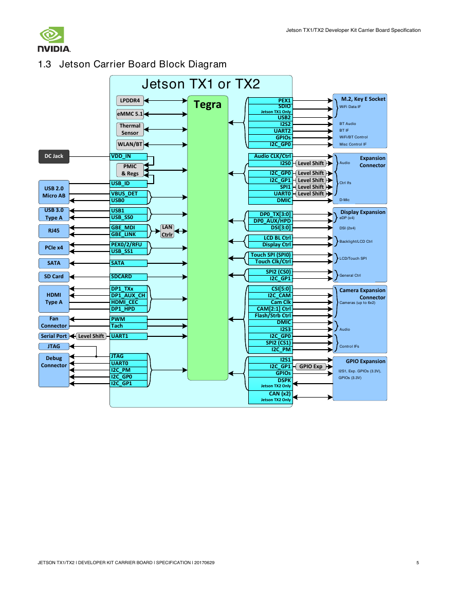
1.3 Jetson Carrier Board Block Diagram
Jetson TX1/TX2 Developer Kit Carrier Board Specification
JETSON TX1/TX2 | DEVELOPER KIT CARRIER BOARD | SPECIFICATION | 20170629
5
Jetson TX1 or TX2USB0USB1ThermalSensorLPDDR4eMMC 5.1LANCtrlrRJ45USB 2.0Micro ABUSB 3.0Type AM.2, Key E SocketSATAPMIC& RegsDC JackWLAN/BTSD CardPCIe x4HDMIType AVDD_INTegraPEX1USB2GBE_MDII2S2GBE_LINKSATASDCARDUART2Audio CLK/CtrlI2S0PEX0/2/RFUI2C_CAMCam ClkI2C_GP0CSI[5:0]DP1_TXxSDIOJetson TX1 OnlyLCD BL CtrlUSB_SS0CAM[2:1] CtrlDP0_TX[3:0]USB_SS1Display CtrlDebug ConnectorFanConnectorI2S1GPIOsPWMJTAGI2C_GP1UART0Touch Clk/CtrlVBUS_DETUSB_IDI2C_GP0SPI2 (CS1)DSI[3:0]Touch SPI (SPI0)SPI2 (CS0)DP1_AUX_CHHDMI_CECDP1_HPDDisplay ExpansionCamera ExpansionConnectorExpansionConnectorDP0_AUX/HPDeDP (x4)DSI (2x4)Backlight/LCD CtrlLCD/Touch SPIGeneral CtrlFlash/Strb CtrlDMICCameras (up to 6x2)AudioControl IFsWiFi Data IFBT AudioBT IFWiFi/BT ControlMisc Control IFGPIOsI2C_GP0Level ShiftI2C_GP1Level ShiftLevel ShiftSPI1Level ShiftUART0Level ShiftAudioCtrl IfsD-MicGPIO ExpansionI2S1, Exp. GPIOs (3.3V), GPIOs (3.3V)I2C_GP1GPIO ExpI2C_PMI2C_GP0I2C_GP1JTAGI2S3I2C_PMTachSerial PortUART1Level ShiftCAN (x2)Jetson TX2 OnlyDSPKJetson TX2 OnlyDMIC�
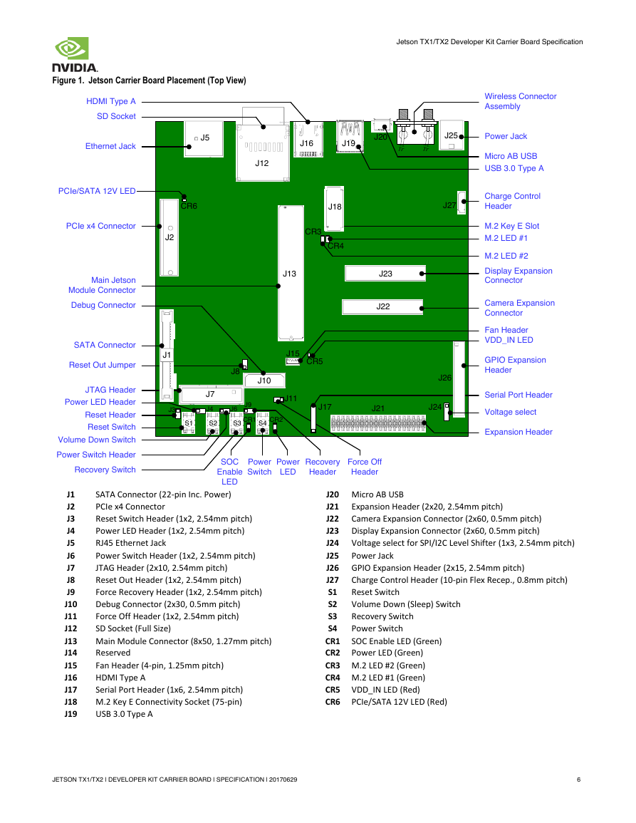
Figure 1. Jetson Carrier Board Placement (Top View)
Jetson TX1/TX2 Developer Kit Carrier Board Specification
J1
J2
J3
J4
J5
J6
J7
J8
J9
J10
J11
J12
J13
J14
J15
J16
J17
J18
J19
SATA Connector (22-pin Inc. Power)
PCIe x4 Connector
Reset Switch Header (1x2, 2.54mm pitch)
Power LED Header (1x2, 2.54mm pitch)
RJ45 Ethernet Jack
Power Switch Header (1x2, 2.54mm pitch)
JTAG Header (2x10, 2.54mm pitch)
Reset Out Header (1x2, 2.54mm pitch)
Force Recovery Header (1x2, 2.54mm pitch)
Debug Connector (2x30, 0.5mm pitch)
Force Off Header (1x2, 2.54mm pitch)
SD Socket (Full Size)
Main Module Connector (8x50, 1.27mm pitch)
Reserved
Fan Header (4-pin, 1.25mm pitch)
HDMI Type A
Serial Port Header (1x6, 2.54mm pitch)
M.2 Key E Connectivity Socket (75-pin)
USB 3.0 Type A
Power Jack
J20 Micro AB USB
Expansion Header (2x20, 2.54mm pitch)
J21
J22
Camera Expansion Connector (2x60, 0.5mm pitch)
J23 Display Expansion Connector (2x60, 0.5mm pitch)
J24 Voltage select for SPI/I2C Level Shifter (1x3, 2.54mm pitch)
J25
J26 GPIO Expansion Header (2x15, 2.54mm pitch)
J27
S1
S2
S3
S4
CR1
CR2 Power LED (Green)
CR3 M.2 LED #2 (Green)
CR4 M.2 LED #1 (Green)
CR5 VDD_IN LED (Red)
CR6 PCIe/SATA 12V LED (Red)
Charge Control Header (10-pin Flex Recep., 0.8mm pitch)
Reset Switch
Volume Down (Sleep) Switch
Recovery Switch
Power Switch
SOC Enable LED (Green)
JETSON TX1/TX2 | DEVELOPER KIT CARRIER BOARD | SPECIFICATION | 20170629
6
J12J5J16J20J15S1J21J26J17J27CR3CR4Main JetsonModule ConnectorSerial Port HeaderFan HeaderPCIe x4 ConnectorJTAG HeaderSATA ConnectorPower JackMicro AB USBDisplay Expansion ConnectorEthernet JackHDMI Type AExpansion HeaderM.2 Key E SlotSD SocketGPIO Expansion HeaderVoltage selectUSB 3.0 Type ACharge Control HeaderDebug ConnectorCamera Expansion ConnectorPower LED HeaderReset SwitchVolume Down SwitchPower Switch HeaderRecovery SwitchPowerSwitchSOCEnableLEDPowerLEDM.2 LED #2M.2 LED #1CR2CR1J6J4S2S3S4J19J25J18J13J23J22J9J3J7J10J1J2J24J11J8Reset Out JumperReset HeaderRecovery HeaderForce OffHeaderCR5VDD_IN LEDCR6PCIe/SATA 12V LEDWireless Connector Assembly�
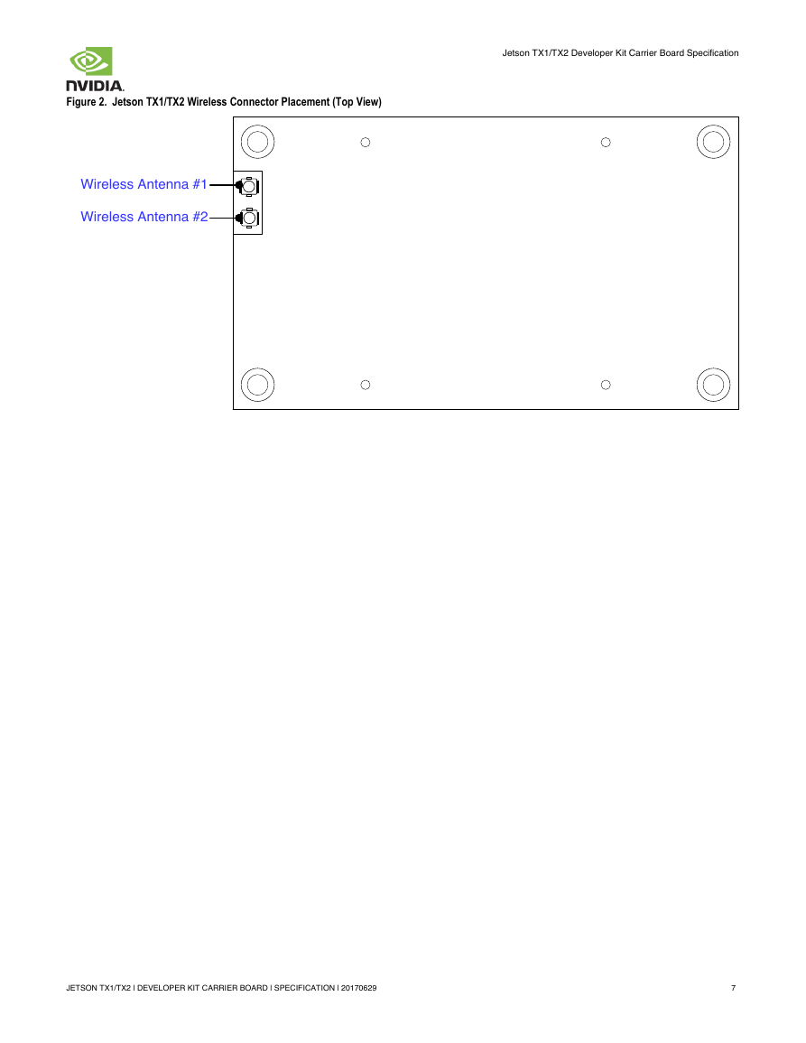
Figure 2. Jetson TX1/TX2 Wireless Connector Placement (Top View)
Jetson TX1/TX2 Developer Kit Carrier Board Specification
JETSON TX1/TX2 | DEVELOPER KIT CARRIER BOARD | SPECIFICATION | 20170629
7
Wireless Antenna #2Wireless Antenna #1�
Jetson TX1/TX2 Developer Kit Carrier Board Specification
2.0 JETSON CARRIER BOARD STANDARD CONNECTORS
The Jetson carrier board provides a number of standard expansion connectors to support additional functionality beyond what is
integrated on the main platform board. This includes:
SATA: Standard SATA Connector, 22-pin including power
SD Card (Full size) Connector/Cage
▪ USB 2.0: Micro AB Connector
▪ USB 3.0: Type A Connector
▪ Gigabit Ethernet: RJ45 Connector
▪
▪
▪ HDMI: Type A Connector
▪ M.2, Key E Socket
▪
▪
PCIe® x4 Connector
JTAG header, 2x10, 2.54mm pitch
2.1 USB Ports
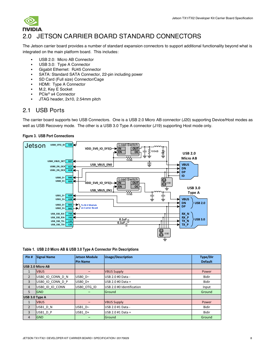
The carrier board supports two USB Connectors. One is a USB 2.0 Micro AB connector (J20) supporting Device/Host modes as
well as USB Recovery mode. The other is a USB 3.0 Type A connector (J19) supporting Host mode only.
Figure 3. USB Port Connections
Table 1. USB 2.0 Micro AB & USB 3.0 Type A Connector Pin Descriptions
Pin # Signal Name
Jetson Module
Pin Name
Usage/Description
USB 2.0 Micro AB
1
2
3
4
5
VBUS
USB0_IO_CONN_D_N
USB0_IO_CONN_D_P
USB0_ID_IO_CONN
GND
USB 3.0 Type A
VBUS
USB1_D_N
USB1_D_P
GND
1
2
3
4
–
USB0_D–
USB0_D+
USB0_OTG_ID
–
–
USB1_D–
USB1_D+
–
VBUS Supply
USB 2.0 #0 Data -
USB 2.0 #0 Data +
USB 2.0 #0 Identification
Ground
VBUS Supply
USB 2.0 #1 Data -
USB 2.0 #1 Data +
Ground
Type/Dir
Default
Power
Bidir
Bidir
Input
Ground
Power
Bidir
Bidir
Ground
JETSON TX1/TX2 | DEVELOPER KIT CARRIER BOARD | SPECIFICATION | 20170629
8
JetsonUSB_VBUS_EN0ESDESDLoad SwitchENOCINOUTVDD_5V0_IO_SYSUSB_VBUS_EN1Load SwitchENOCINOUTVDD_5V0_IO_SYSUSB0_D–USB0_D+USB1_D–USB1_D+USB2_D–USB2_D+USB_SS0_RX–USB_SS0_RX+USB_SS0_TX–USB_SS0_TX+USB0_OTG_IDUSB0_VBUS_DETUSB0_EN_OC#USB1_EN_OC#To M.2 Module on Carrier BoardA36A17A18B39B37B40A38A39B42B43C43C44F43F440.1uF0.1uF100kΩVBUSDNDPRX_NRX_PTX_NTX_PUSB 2.0USB 3.0VBUSDNDPIDUSB 2.0Micro ABUSB 3.0Type A100Ω100Ω�



 2023年江西萍乡中考道德与法治真题及答案.doc
 2012年重庆南川中考生物真题及答案.doc
 2013年江西师范大学地理学综合及文艺理论基础考研真题.doc
 2020年四川甘孜小升初语文真题及答案I卷.doc
 2020年注册岩土工程师专业基础考试真题及答案.doc
 2023-2024学年福建省厦门市九年级上学期数学月考试题及答案.doc
 2021-2022学年辽宁省沈阳市大东区九年级上学期语文期末试题及答案.doc
 2022-2023学年北京东城区初三第一学期物理期末试卷及答案.doc
 2018上半年江西教师资格初中地理学科知识与教学能力真题及答案.doc
 2012年河北国家公务员申论考试真题及答案-省级.doc
 2020-2021学年江苏省扬州市江都区邵樊片九年级上学期数学第一次质量检测试题及答案.doc
 2022下半年黑龙江教师资格证中学综合素质真题及答案.doc