logo资料库

xilinx DPD document.pdf

第1页 / 共158页
第2页 / 共158页
第3页 / 共158页
第4页 / 共158页
第5页 / 共158页
第6页 / 共158页
第7页 / 共158页
第8页 / 共158页
资料共158页,剩余部分请下载后查看
Digital Predistortion v2.0
Summary
Table of Contents
List of Figures
List of Tables
Introduction
Benefits of DPD
Spectral Mask Compliance
Output Power Efficiency
Xilinx DPD Solution
Document Plan
DPD Algorithm and Architecture Design
Mathematical Foundation
System Architecture
High-Level Design
Predistorter
Capture Buffers and Estimation Core Function (ECF)
Measurements Block and Sample Capture Acceptance (SCA)
Dynamic Control Layer (DCL)
Dual Transmit Path DPD
Quadrature Modulator Correction Algorithm Overview
Introduction
Extending the Xilinx DPD Solution to Support QMC
Required Software to Support QMC
Quadrature Modulator (QM) Error Detectors
Updating the QMC Registers
Setting QMC Parameters
Over-Drive Detection Algorithm Overview
Overview
ODD Architecture Description
Accounting for the Frequency Response of the DPD Filter
Details of the Over-Drive Detection Algorithm within Xilinx DPD
Algorithm Implementation
Overall Structure
Sample Rate Datapath
dpd_sampleratepath: Dpd_tx_path and LUTs
dpd_sampleratepath: Capture RAM
dpd_sampleratepath: Measurements
dpd_sampleratepath: QMC
dpd_sampleratepath: Dual Tx Support
dpd_updatepath
dpd_updatepath: Software Memory Map
dpd_updatepath: Hardware Memory Map
Software Design
Performance Testing
Test Infrastructure
Hardware
FPGA Design
DPD Correction Performance
WCDMA
WiMAX
LTE
TD-SCDMA
Multicarrier GSM
Mixed-mode LTE/Multicarrier GSM
Dynamics
FPGA Resource Utilization, Timing Performance, and Power Consumption
FPGA Resource Utilization
Timing Performance
Power Consumption
Using the Hardware Design Files
Overview
Software Tools Requirements
IP Core ZIP File Descriptions
Interface Description
Port Description
Interfaces
Generating DPD netlist
Instantiation Example
Using dpd_build.bat Script
Constraints
Running Simulation in System Generator
Hardware in the Loop in System Generator
Instantiating in a User Design
Instantiating dpd_1tx_cw (dpd_2tx_cw)
Modifying Various Project Files
Using the Supplied Software
Control Shell Interface
Control Modes
Status Indicators
ECF Parameters and Status Monitoring
Estimation Parameter Tests
DCL Parameters and Status Monitoring
Coefficient Management
System Integration
Requirements
Sample Rates
Required Signal Levels and Properties
RF Performance
Placement in the Signal Chain
Operations Guide
Initial Setup and Debug
Amplifier Characterization
Establishing DPD Parameters
References
Conclusion
Appendix A: Abbreviations
Appendix B: Using Executable Control Modes
Selecting Which Port to Control
Loading New ECF Parameters Command
UPDATE_ECF_PARAMETERS{17}
Loading New QMC Parameters Command
SET_QMC_PARAMS{26}
Loading New DCL Parameters Command
SET_DCL_PARAMETERS{12}
Determining P_Step Parameter
Run DCL Controller Command
RUN_DCL{14}
DCL Command Routines
Run DCL Controller with QMC Command
RUN_DCL_WITH_QMC{27}
Run DCL Controller with Accelerated Startup QMC Command
RUN_DCL_WITH_ACCEL_QMC{23}
Exit DCL Controller Command
EXIT_DCL{18}
Capture New Set of Samples in the Capture RAM Command
CAPTURE_NEW_SAMPLES{20}
Run a Single Iteration of the DPD Update Algorithm Command
COMPUTE_NEW_COEFFICIENTS{2}
Run a Single Iteration of the QMC Update Algorithm Command
QMC_SINGLE_STEP{22}
Reset the Coefficients Command
RESET_COEFFICIENTS{3}
Reset the QMC Coefficients Command
RESET_QMC{21}
Enable External RX Path Select Control Command
ENABLE_EXT_RXSEL{28}
Enable Internal RX Path Select Control Command
ENABLE_INT_RXSEL{29}
Set Meter Length Command
SET_METER_LENGTH{6}
Read the Power Meters Command
READ_POWER_METERS{13}
Read the Capture Power Meter Command
READ_CAPTURE_POWER_METERS{16}
Read Capture RAM Contents Command
GET_CAPTURE_RAM_PAGE{4}
Read the Histogram Command
GET_HISTOGRAM_PAGE{5}
Read the Capture Histogram Command
GET_CAPTURE_HISTOGRAM_PAGE{15}
Turn QMC OFF Command
QMC_OFF{25}
Turn QMC ON Command
QMC_ON{24}
Turn DPD OFF Command
DPD_OFF{7}
Turn DPD ON 0 Command
DPD_ON_0{8}
Turn DPD ON 1 Command
DPD_ON_1{9}
Turn DPD ON 2 Command
DPD_ON_2{10}
Set Capture Parameters Command
SET_CAPTURE_PARAMS{11}
Read DPD Parameters Command
READ_CONFIGURATION{1}
Restore Default Configuration Command
RESTORE_DEFAULTS{19}
Command/Monitoring Examples
Example 1 - Dumping the Full 4K Samples
Example 2 - Dumping the Full Histogram
Example 3 - Reading the Full Power Meters
Appendix C: SBRAM Memory Map
Appendix D: Dual Antenna SBRAM Memory Map
Revision History
Support
Notice of Disclaimer
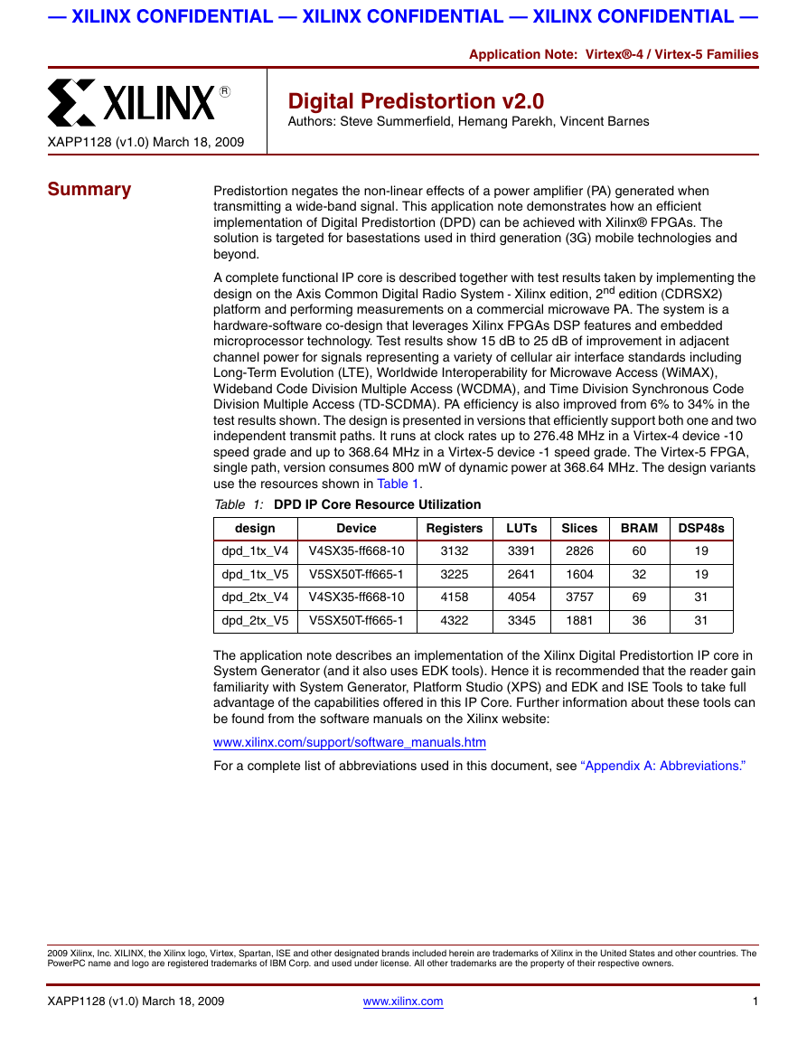
— XILINX CONFIDENTIAL — XILINX CONFIDENTIAL — XILINX CONFIDENTIAL — Application Note: Virtex®-4 / Virtex-5 Families R Digital Predistortion v2.0 Authors: Steve Summerfield, Hemang Parekh, Vincent Barnes XAPP1128 (v1.0) March 18, 2009 Summary Predistortion negates the non-linear effects of a power amplifier (PA) generated when transmitting a wide-band signal. This application note demonstrates how an efficient implementation of Digital Predistortion (DPD) can be achieved with Xilinx® FPGAs. The solution is targeted for basestations used in third generation (3G) mobile technologies and beyond. A complete functional IP core is described together with test results taken by implementing the design on the Axis Common Digital Radio System - Xilinx edition, 2nd edition (CDRSX2) platform and performing measurements on a commercial microwave PA. The system is a hardware-software co-design that leverages Xilinx FPGAs DSP features and embedded microprocessor technology. Test results show 15 dB to 25 dB of improvement in adjacent channel power for signals representing a variety of cellular air interface standards including Long-Term Evolution (LTE), Worldwide Interoperability for Microwave Access (WiMAX), Wideband Code Division Multiple Access (WCDMA), and Time Division Synchronous Code Division Multiple Access (TD-SCDMA). PA efficiency is also improved from 6% to 34% in the test results shown. The design is presented in versions that efficiently support both one and two independent transmit paths. It runs at clock rates up to 276.48 MHz in a Virtex-4 device -10 speed grade and up to 368.64 MHz in a Virtex-5 device -1 speed grade. The Virtex-5 FPGA, single path, version consumes 800 mW of dynamic power at 368.64 MHz. The design variants use the resources shown in Table 1. Table 1: DPD IP Core Resource Utilization design Device Registers LUTs Slices BRAM DSP48s dpd_1tx_V4 V4SX35-ff668-10 dpd_1tx_V5 V5SX50T-ff665-1 dpd_2tx_V4 V4SX35-ff668-10 dpd_2tx_V5 V5SX50T-ff665-1 3132 3225 4158 4322 3391 2641 4054 3345 2826 1604 3757 1881 60 32 69 36 19 19 31 31 The application note describes an implementation of the Xilinx Digital Predistortion IP core in System Generator (and it also uses EDK tools). Hence it is recommended that the reader gain familiarity with System Generator, Platform Studio (XPS) and EDK and ISE Tools to take full advantage of the capabilities offered in this IP Core. Further information about these tools can be found from the software manuals on the Xilinx website: www.xilinx.com/support/software_manuals.htm For a complete list of abbreviations used in this document, see “Appendix A: Abbreviations.” 2009 Xilinx, Inc. XILINX, the Xilinx logo, Virtex, Spartan, ISE and other designated brands included herein are trademarks of Xilinx in the United States and other countries. The PowerPC name and logo are registered trademarks of IBM Corp. and used under license. All other trademarks are the property of their respective owners. XAPP1128 (v1.0) March 18, 2009 www.xilinx.com 1
— XILINX CONFIDENTIAL — XILINX CONFIDENTIAL — XILINX CONFIDENTIAL — Table of Contents R Table of Contents Summary . . . . . . . . . . . . . . . . . . . . . . . . . . . . . . . . . . . . . . . . . . . . . . . . . . . . . . . . . . . . . . . . . . . . . . . . 1 Table of Contents . . . . . . . . . . . . . . . . . . . . . . . . . . . . . . . . . . . . . . . . . . . . . . . . . . . . . . . . . . . . . . . . . . 2 List of Figures. . . . . . . . . . . . . . . . . . . . . . . . . . . . . . . . . . . . . . . . . . . . . . . . . . . . . . . . . . . . . . . . . . . . . 5 List of Tables . . . . . . . . . . . . . . . . . . . . . . . . . . . . . . . . . . . . . . . . . . . . . . . . . . . . . . . . . . . . . . . . . . . . . 7 Introduction. . . . . . . . . . . . . . . . . . . . . . . . . . . . . . . . . . . . . . . . . . . . . . . . . . . . . . . . . . . . . . . . . . . . . . . 8 Benefits of DPD . . . . . . . . . . . . . . . . . . . . . . . . . . . . . . . . . . . . . . . . . . . . . . . . . . . . . . . . . . . . . 8 Spectral Mask Compliance . . . . . . . . . . . . . . . . . . . . . . . . . . . . . . . . . . . . . . . . . . . . . . . . 8 Output Power Efficiency. . . . . . . . . . . . . . . . . . . . . . . . . . . . . . . . . . . . . . . . . . . . . . . . . . . 10 Xilinx DPD Solution . . . . . . . . . . . . . . . . . . . . . . . . . . . . . . . . . . . . . . . . . . . . . . . . . . . . . . . . . . 11 Document Plan. . . . . . . . . . . . . . . . . . . . . . . . . . . . . . . . . . . . . . . . . . . . . . . . . . . . . . . . . . . . . . 12 DPD Algorithm and Architecture Design . . . . . . . . . . . . . . . . . . . . . . . . . . . . . . . . . . . . . . . . . . . . . . . . 13 System Architecture . . . . . . . . . . . . . . . . . . . . . . . . . . . . . . . . . . . . . . . . . . . . . . . . . . . . . . . . . . 15 High-Level Design . . . . . . . . . . . . . . . . . . . . . . . . . . . . . . . . . . . . . . . . . . . . . . . . . . . . . . . 15 Predistorter. . . . . . . . . . . . . . . . . . . . . . . . . . . . . . . . . . . . . . . . . . . . . . . . . . . . . . . . . . . . . 16 Capture Buffers and Estimation Core Function (ECF) . . . . . . . . . . . . . . . . . . . . . . . . . . . . 17 Measurements Block and Sample Capture Acceptance (SCA) . . . . . . . . . . . . . . . . . . . . . 18 Dynamic Control Layer (DCL) . . . . . . . . . . . . . . . . . . . . . . . . . . . . . . . . . . . . . . . . . . . . . . 19 DCL for QSNL Amplifiers . . . . . . . . . . . . . . . . . . . . . . . . . . . . . . . . . . . . . . . . . . . . . . 20 DCL for NSNL Amplifiers . . . . . . . . . . . . . . . . . . . . . . . . . . . . . . . . . . . . . . . . . . . . . . 21 Dual Transmit Path DPD . . . . . . . . . . . . . . . . . . . . . . . . . . . . . . . . . . . . . . . . . . . . . . . . . . 23 FPGA Hardware. . . . . . . . . . . . . . . . . . . . . . . . . . . . . . . . . . . . . . . . . . . . . . . . . . . . . 23 Software Design. . . . . . . . . . . . . . . . . . . . . . . . . . . . . . . . . . . . . . . . . . . . . . . . . . . . . 24 Quadrature Modulator Correction Algorithm Overview. . . . . . . . . . . . . . . . . . . . . . . . . . . . . . . . . . . . . . 25 Extending the Xilinx DPD Solution to Support QMC . . . . . . . . . . . . . . . . . . . . . . . . . . . . . . . . . 27 Required Software to Support QMC. . . . . . . . . . . . . . . . . . . . . . . . . . . . . . . . . . . . . . . . . . . . . . 28 Quadrature Modulator (QM) Error Detectors . . . . . . . . . . . . . . . . . . . . . . . . . . . . . . . . . . . 28 Updating the QMC Registers . . . . . . . . . . . . . . . . . . . . . . . . . . . . . . . . . . . . . . . . . . . . . . . 30 Setting QMC Parameters . . . . . . . . . . . . . . . . . . . . . . . . . . . . . . . . . . . . . . . . . . . . . . . . . . 32 Over-Drive Detection Algorithm Overview . . . . . . . . . . . . . . . . . . . . . . . . . . . . . . . . . . . . . . . . . . . . . . . 33 ODD Architecture Description . . . . . . . . . . . . . . . . . . . . . . . . . . . . . . . . . . . . . . . . . . . . . . . . . . 33 Accounting for the Frequency Response of the DPD Filter . . . . . . . . . . . . . . . . . . . . . . . . . . . . 35 Details of the Over-Drive Detection Algorithm within Xilinx DPD . . . . . . . . . . . . . . . . . . . . . . . . 37 Algorithm Implementation. . . . . . . . . . . . . . . . . . . . . . . . . . . . . . . . . . . . . . . . . . . . . . . . . . . . . . . . . . . . 41 Sample Rate Datapath . . . . . . . . . . . . . . . . . . . . . . . . . . . . . . . . . . . . . . . . . . . . . . . . . . . . . . . . 45 dpd_sampleratepath: Dpd_tx_path and LUTs . . . . . . . . . . . . . . . . . . . . . . . . . . . . . . . . . . 47 dpd_sampleratepath: Capture RAM. . . . . . . . . . . . . . . . . . . . . . . . . . . . . . . . . . . . . . . . . . 51 dpd_sampleratepath: Measurements. . . . . . . . . . . . . . . . . . . . . . . . . . . . . . . . . . . . . . . . . 55 dpd_sampleratepath: QMC . . . . . . . . . . . . . . . . . . . . . . . . . . . . . . . . . . . . . . . . . . . . . . . . 60 dpd_sampleratepath: Dual Tx Support . . . . . . . . . . . . . . . . . . . . . . . . . . . . . . . . . . . . . . . 61 dpd_updatepath . . . . . . . . . . . . . . . . . . . . . . . . . . . . . . . . . . . . . . . . . . . . . . . . . . . . . . . . . . . . . 62 dpd_updatepath: Software Memory Map . . . . . . . . . . . . . . . . . . . . . . . . . . . . . . . . . . . . . . 64 dpd_updatepath: Hardware Memory Map . . . . . . . . . . . . . . . . . . . . . . . . . . . . . . . . . . . . . 66 Control Registers . . . . . . . . . . . . . . . . . . . . . . . . . . . . . . . . . . . . . . . . . . . . . . . . . . . . 66 Measurements Registers . . . . . . . . . . . . . . . . . . . . . . . . . . . . . . . . . . . . . . . . . . . . . . 67 LUT Memories . . . . . . . . . . . . . . . . . . . . . . . . . . . . . . . . . . . . . . . . . . . . . . . . . . . . . . 67 Capture Memory . . . . . . . . . . . . . . . . . . . . . . . . . . . . . . . . . . . . . . . . . . . . . . . . . . . . 67 Host Interface Memory (Shared Block RAM) . . . . . . . . . . . . . . . . . . . . . . . . . . . . . . . 68 Software Design . . . . . . . . . . . . . . . . . . . . . . . . . . . . . . . . . . . . . . . . . . . . . . . . . . . . . . . . . . . . . 68 Performance Testing . . . . . . . . . . . . . . . . . . . . . . . . . . . . . . . . . . . . . . . . . . . . . . . . . . . . . . . . . . . . . . . 70 Test Infrastructure . . . . . . . . . . . . . . . . . . . . . . . . . . . . . . . . . . . . . . . . . . . . . . . . . . . . . . . . . . . 70 Hardware . . . . . . . . . . . . . . . . . . . . . . . . . . . . . . . . . . . . . . . . . . . . . . . . . . . . . . . . . . . . . . 70 FPGA Design . . . . . . . . . . . . . . . . . . . . . . . . . . . . . . . . . . . . . . . . . . . . . . . . . . . . . . . . . . . . . . . 71 DPD Correction Performance. . . . . . . . . . . . . . . . . . . . . . . . . . . . . . . . . . . . . . . . . . . . . . . . . . . 72 WCDMA . . . . . . . . . . . . . . . . . . . . . . . . . . . . . . . . . . . . . . . . . . . . . . . . . . . . . . . . . . . . . . . 72 WiMAX . . . . . . . . . . . . . . . . . . . . . . . . . . . . . . . . . . . . . . . . . . . . . . . . . . . . . . . . . . . . . . . . 75 LTE. . . . . . . . . . . . . . . . . . . . . . . . . . . . . . . . . . . . . . . . . . . . . . . . . . . . . . . . . . . . . . . . . . . 77 TD-SCDMA . . . . . . . . . . . . . . . . . . . . . . . . . . . . . . . . . . . . . . . . . . . . . . . . . . . . . . . . . . . . 78 Multicarrier GSM . . . . . . . . . . . . . . . . . . . . . . . . . . . . . . . . . . . . . . . . . . . . . . . . . . . . . . . . 80 Mixed-mode LTE/Multicarrier GSM . . . . . . . . . . . . . . . . . . . . . . . . . . . . . . . . . . . . . . . . . . 81 Dynamics . . . . . . . . . . . . . . . . . . . . . . . . . . . . . . . . . . . . . . . . . . . . . . . . . . . . . . . . . . . . . . 81 Convergence and Stability . . . . . . . . . . . . . . . . . . . . . . . . . . . . . . . . . . . . . . . . . . . . . 82 Dynamic Carrier Power . . . . . . . . . . . . . . . . . . . . . . . . . . . . . . . . . . . . . . . . . . . . . . . 83 Fast Dynamics . . . . . . . . . . . . . . . . . . . . . . . . . . . . . . . . . . . . . . . . . . . . . . . . . . . . . . 84 XAPP1128 (v1.0) March 18, 2009 www.xilinx.com 2
— XILINX CONFIDENTIAL — XILINX CONFIDENTIAL — XILINX CONFIDENTIAL — Table of Contents R DPD-QMC Performance . . . . . . . . . . . . . . . . . . . . . . . . . . . . . . . . . . . . . . . . . . . . . . 85 Dual tx Path Performance . . . . . . . . . . . . . . . . . . . . . . . . . . . . . . . . . . . . . . . . . . . . . 86 FPGA Resource Utilization, Timing Performance, and Power Consumption . . . . . . . . . . . . . . . . . . . . . 87 Timing Performance . . . . . . . . . . . . . . . . . . . . . . . . . . . . . . . . . . . . . . . . . . . . . . . . . . . . . . . . . . 87 Power Consumption . . . . . . . . . . . . . . . . . . . . . . . . . . . . . . . . . . . . . . . . . . . . . . . . . . . . . . . . . . 87 Using the Hardware Design Files. . . . . . . . . . . . . . . . . . . . . . . . . . . . . . . . . . . . . . . . . . . . . . . . . . . . . . 90 Software Tools Requirements . . . . . . . . . . . . . . . . . . . . . . . . . . . . . . . . . . . . . . . . . . . . . . . . . . 90 IP Core ZIP File Descriptions . . . . . . . . . . . . . . . . . . . . . . . . . . . . . . . . . . . . . . . . . . . . . . . . . . . 90 Interface Description . . . . . . . . . . . . . . . . . . . . . . . . . . . . . . . . . . . . . . . . . . . . . . . . . . . . . . . . . 91 Port Description . . . . . . . . . . . . . . . . . . . . . . . . . . . . . . . . . . . . . . . . . . . . . . . . . . . . . . . . . 91 Interfaces . . . . . . . . . . . . . . . . . . . . . . . . . . . . . . . . . . . . . . . . . . . . . . . . . . . . . . . . . . . . . . 93 Clock Interface . . . . . . . . . . . . . . . . . . . . . . . . . . . . . . . . . . . . . . . . . . . . . . . . . . . . . . 93 Reset Interface. . . . . . . . . . . . . . . . . . . . . . . . . . . . . . . . . . . . . . . . . . . . . . . . . . . . . . 95 Data Path Interface . . . . . . . . . . . . . . . . . . . . . . . . . . . . . . . . . . . . . . . . . . . . . . . . . . 95 SRx Interface . . . . . . . . . . . . . . . . . . . . . . . . . . . . . . . . . . . . . . . . . . . . . . . . . . . . . . . 96 Host Interface. . . . . . . . . . . . . . . . . . . . . . . . . . . . . . . . . . . . . . . . . . . . . . . . . . . . . . . 97 Dual Antenna Interface . . . . . . . . . . . . . . . . . . . . . . . . . . . . . . . . . . . . . . . . . . . . . . . 97 Generating DPD netlist. . . . . . . . . . . . . . . . . . . . . . . . . . . . . . . . . . . . . . . . . . . . . . . . . . . . . . . . 98 Instantiation Example . . . . . . . . . . . . . . . . . . . . . . . . . . . . . . . . . . . . . . . . . . . . . . . . . . . . . . . . . 100 Using dpd_build.bat Script . . . . . . . . . . . . . . . . . . . . . . . . . . . . . . . . . . . . . . . . . . . . . . . . . 101 Constraints . . . . . . . . . . . . . . . . . . . . . . . . . . . . . . . . . . . . . . . . . . . . . . . . . . . . . . . . . . . . . 101 Running Simulation in System Generator . . . . . . . . . . . . . . . . . . . . . . . . . . . . . . . . . . . . . . . . . 103 Hardware in the Loop in System Generator. . . . . . . . . . . . . . . . . . . . . . . . . . . . . . . . . . . . 103 Instantiating in a User Design . . . . . . . . . . . . . . . . . . . . . . . . . . . . . . . . . . . . . . . . . . . . . . . . . . 104 Instantiating dpd_1tx_cw (dpd_2tx_cw) . . . . . . . . . . . . . . . . . . . . . . . . . . . . . . . . . . . . . . . 104 Modifying Various Project Files . . . . . . . . . . . . . . . . . . . . . . . . . . . . . . . . . . . . . . . . . . . . . 104 Using the Supplied Software . . . . . . . . . . . . . . . . . . . . . . . . . . . . . . . . . . . . . . . . . . . . . . . . . . . . . . . . . 106 Control Shell Interface . . . . . . . . . . . . . . . . . . . . . . . . . . . . . . . . . . . . . . . . . . . . . . . . . . . . . . . . 107 Control Modes . . . . . . . . . . . . . . . . . . . . . . . . . . . . . . . . . . . . . . . . . . . . . . . . . . . . . . . . . . 109 Triggering a Control Mode . . . . . . . . . . . . . . . . . . . . . . . . . . . . . . . . . . . . . . . . . . . . . 109 Supplied Control Modes. . . . . . . . . . . . . . . . . . . . . . . . . . . . . . . . . . . . . . . . . . . . . . . 110 Status Indicators . . . . . . . . . . . . . . . . . . . . . . . . . . . . . . . . . . . . . . . . . . . . . . . . . . . . . . . . 113 ECF Parameters and Status Monitoring . . . . . . . . . . . . . . . . . . . . . . . . . . . . . . . . . . . . . . 116 ECF Parameters . . . . . . . . . . . . . . . . . . . . . . . . . . . . . . . . . . . . . . . . . . . . . . . . . . . . 116 Estimation Parameter Tests. . . . . . . . . . . . . . . . . . . . . . . . . . . . . . . . . . . . . . . . . . . . . . . . 116 ECF Monitoring . . . . . . . . . . . . . . . . . . . . . . . . . . . . . . . . . . . . . . . . . . . . . . . . . . . . . 117 DCL Parameters and Status Monitoring . . . . . . . . . . . . . . . . . . . . . . . . . . . . . . . . . . . . . . 118 DCL Parameters . . . . . . . . . . . . . . . . . . . . . . . . . . . . . . . . . . . . . . . . . . . . . . . . . . . . 118 DCL Monitoring . . . . . . . . . . . . . . . . . . . . . . . . . . . . . . . . . . . . . . . . . . . . . . . . . . . . . 119 Coefficient Management . . . . . . . . . . . . . . . . . . . . . . . . . . . . . . . . . . . . . . . . . . . . . . . . . . . . . . 120 System Integration . . . . . . . . . . . . . . . . . . . . . . . . . . . . . . . . . . . . . . . . . . . . . . . . . . . . . . . . . . . . . . . . . 122 Sample Rates. . . . . . . . . . . . . . . . . . . . . . . . . . . . . . . . . . . . . . . . . . . . . . . . . . . . . . . . . . . 122 Required Signal Levels and Properties . . . . . . . . . . . . . . . . . . . . . . . . . . . . . . . . . . . . . . . 122 RF Performance. . . . . . . . . . . . . . . . . . . . . . . . . . . . . . . . . . . . . . . . . . . . . . . . . . . . . . . . . 123 Placement in the Signal Chain . . . . . . . . . . . . . . . . . . . . . . . . . . . . . . . . . . . . . . . . . . . . . . . . . . 123 Operations Guide . . . . . . . . . . . . . . . . . . . . . . . . . . . . . . . . . . . . . . . . . . . . . . . . . . . . . . . . . . . . 123 Initial Setup and Debug . . . . . . . . . . . . . . . . . . . . . . . . . . . . . . . . . . . . . . . . . . . . . . . . . . . 123 Amplifier Characterization . . . . . . . . . . . . . . . . . . . . . . . . . . . . . . . . . . . . . . . . . . . . . . . . . 125 Establishing DPD Parameters . . . . . . . . . . . . . . . . . . . . . . . . . . . . . . . . . . . . . . . . . . . . . . 125 Capture Mode . . . . . . . . . . . . . . . . . . . . . . . . . . . . . . . . . . . . . . . . . . . . . . . . . . . . . . 125 Estimation Parameters. . . . . . . . . . . . . . . . . . . . . . . . . . . . . . . . . . . . . . . . . . . . . . . . 125 DCL Parameters . . . . . . . . . . . . . . . . . . . . . . . . . . . . . . . . . . . . . . . . . . . . . . . . . . . . 126 Control and Monitoring. . . . . . . . . . . . . . . . . . . . . . . . . . . . . . . . . . . . . . . . . . . . . . . . 126 References . . . . . . . . . . . . . . . . . . . . . . . . . . . . . . . . . . . . . . . . . . . . . . . . . . . . . . . . . . . . . . . . . . . . . . . 127 Conclusion . . . . . . . . . . . . . . . . . . . . . . . . . . . . . . . . . . . . . . . . . . . . . . . . . . . . . . . . . . . . . . . . . . . . . . . 127 Appendix A: Abbreviations . . . . . . . . . . . . . . . . . . . . . . . . . . . . . . . . . . . . . . . . . . . . . . . . . . . . . . . . . . . 128 Appendix B: Using Executable Control Modes. . . . . . . . . . . . . . . . . . . . . . . . . . . . . . . . . . . . . . . . . . . . 129 Loading New ECF Parameters Command . . . . . . . . . . . . . . . . . . . . . . . . . . . . . . . . . . . . . . . . . 129 UPDATE_ECF_PARAMETERS{17} . . . . . . . . . . . . . . . . . . . . . . . . . . . . . . . . . . . . . . . . . 129 Loading New QMC Parameters Command . . . . . . . . . . . . . . . . . . . . . . . . . . . . . . . . . . . . . . . . 131 SET_QMC_PARAMS{26} . . . . . . . . . . . . . . . . . . . . . . . . . . . . . . . . . . . . . . . . . . . . . . . . . 131 Loading New DCL Parameters Command . . . . . . . . . . . . . . . . . . . . . . . . . . . . . . . . . . . . . . . . . 132 SET_DCL_PARAMETERS{12} . . . . . . . . . . . . . . . . . . . . . . . . . . . . . . . . . . . . . . . . . . . . . 132 Determining P_Step Parameter . . . . . . . . . . . . . . . . . . . . . . . . . . . . . . . . . . . . . . . . . . . . . 132 Run DCL Controller Command . . . . . . . . . . . . . . . . . . . . . . . . . . . . . . . . . . . . . . . . . . . . . . . . . 133 RUN_DCL{14} . . . . . . . . . . . . . . . . . . . . . . . . . . . . . . . . . . . . . . . . . . . . . . . . . . . . . . . . . . 133 DCL Command Routines . . . . . . . . . . . . . . . . . . . . . . . . . . . . . . . . . . . . . . . . . . . . . . . . . . 135 Run DCL Controller with QMC Command . . . . . . . . . . . . . . . . . . . . . . . . . . . . . . . . . . . . . . . . . 135 XAPP1128 (v1.0) March 18, 2009 www.xilinx.com 3
— XILINX CONFIDENTIAL — XILINX CONFIDENTIAL — XILINX CONFIDENTIAL — Table of Contents R RUN_DCL_WITH_QMC{27} . . . . . . . . . . . . . . . . . . . . . . . . . . . . . . . . . . . . . . . . . . . . . . . 135 Run DCL Controller with Accelerated Startup QMC Command . . . . . . . . . . . . . . . . . . . . . . . . . 136 RUN_DCL_WITH_ACCEL_QMC{23} . . . . . . . . . . . . . . . . . . . . . . . . . . . . . . . . . . . . . . . . 136 Exit DCL Controller Command . . . . . . . . . . . . . . . . . . . . . . . . . . . . . . . . . . . . . . . . . . . . . . . . . . 136 EXIT_DCL{18} . . . . . . . . . . . . . . . . . . . . . . . . . . . . . . . . . . . . . . . . . . . . . . . . . . . . . . . . . . 136 Capture New Set of Samples in the Capture RAM Command. . . . . . . . . . . . . . . . . . . . . . . . . . 136 CAPTURE_NEW_SAMPLES{20} . . . . . . . . . . . . . . . . . . . . . . . . . . . . . . . . . . . . . . . . . . . 136 Run a Single Iteration of the DPD Update Algorithm Command . . . . . . . . . . . . . . . . . . . . . . . . 137 COMPUTE_NEW_COEFFICIENTS{2} . . . . . . . . . . . . . . . . . . . . . . . . . . . . . . . . . . . . . . . 137 Run a Single Iteration of the QMC Update Algorithm Command . . . . . . . . . . . . . . . . . . . . . . . . 138 QMC_SINGLE_STEP{22} . . . . . . . . . . . . . . . . . . . . . . . . . . . . . . . . . . . . . . . . . . . . . . . . . 138 Reset the Coefficients Command. . . . . . . . . . . . . . . . . . . . . . . . . . . . . . . . . . . . . . . . . . . . . . . . 139 RESET_COEFFICIENTS{3} . . . . . . . . . . . . . . . . . . . . . . . . . . . . . . . . . . . . . . . . . . . . . . . 139 Reset the QMC Coefficients Command . . . . . . . . . . . . . . . . . . . . . . . . . . . . . . . . . . . . . . . . . . . 139 RESET_QMC{21} . . . . . . . . . . . . . . . . . . . . . . . . . . . . . . . . . . . . . . . . . . . . . . . . . . . . . . . 139 Enable External RX Path Select Control Command . . . . . . . . . . . . . . . . . . . . . . . . . . . . . . . . . 139 ENABLE_EXT_RXSEL{28} . . . . . . . . . . . . . . . . . . . . . . . . . . . . . . . . . . . . . . . . . . . . . . . . 139 Enable Internal RX Path Select Control Command . . . . . . . . . . . . . . . . . . . . . . . . . . . . . . . . . . 140 ENABLE_INT_RXSEL{29} . . . . . . . . . . . . . . . . . . . . . . . . . . . . . . . . . . . . . . . . . . . . . . . . . 140 Set Meter Length Command . . . . . . . . . . . . . . . . . . . . . . . . . . . . . . . . . . . . . . . . . . . . . . . . . . . 140 SET_METER_LENGTH{6}. . . . . . . . . . . . . . . . . . . . . . . . . . . . . . . . . . . . . . . . . . . . . . . . . 140 Read the Power Meters Command . . . . . . . . . . . . . . . . . . . . . . . . . . . . . . . . . . . . . . . . . . . . . . 141 READ_POWER_METERS{13} . . . . . . . . . . . . . . . . . . . . . . . . . . . . . . . . . . . . . . . . . . . . . 141 Read the Capture Power Meter Command . . . . . . . . . . . . . . . . . . . . . . . . . . . . . . . . . . . . . . . . 142 READ_CAPTURE_POWER_METERS{16} . . . . . . . . . . . . . . . . . . . . . . . . . . . . . . . . . . . . 142 Read Capture RAM Contents Command . . . . . . . . . . . . . . . . . . . . . . . . . . . . . . . . . . . . . . . . . . 142 GET_CAPTURE_RAM_PAGE{4} . . . . . . . . . . . . . . . . . . . . . . . . . . . . . . . . . . . . . . . . . . . 142 Read the Histogram Command . . . . . . . . . . . . . . . . . . . . . . . . . . . . . . . . . . . . . . . . . . . . . . . . . 143 GET_HISTOGRAM_PAGE{5} . . . . . . . . . . . . . . . . . . . . . . . . . . . . . . . . . . . . . . . . . . . . . . 143 Read the Capture Histogram Command . . . . . . . . . . . . . . . . . . . . . . . . . . . . . . . . . . . . . . . . . . 144 GET_CAPTURE_HISTOGRAM_PAGE{15} . . . . . . . . . . . . . . . . . . . . . . . . . . . . . . . . . . . 144 Turn QMC OFF Command. . . . . . . . . . . . . . . . . . . . . . . . . . . . . . . . . . . . . . . . . . . . . . . . . . . . . 144 QMC_OFF{25} . . . . . . . . . . . . . . . . . . . . . . . . . . . . . . . . . . . . . . . . . . . . . . . . . . . . . . . . . . 144 Turn QMC ON Command. . . . . . . . . . . . . . . . . . . . . . . . . . . . . . . . . . . . . . . . . . . . . . . . . . . . . . 145 QMC_ON{24} . . . . . . . . . . . . . . . . . . . . . . . . . . . . . . . . . . . . . . . . . . . . . . . . . . . . . . . . . . . 145 Turn DPD OFF Command . . . . . . . . . . . . . . . . . . . . . . . . . . . . . . . . . . . . . . . . . . . . . . . . . . . . . 145 DPD_OFF{7} . . . . . . . . . . . . . . . . . . . . . . . . . . . . . . . . . . . . . . . . . . . . . . . . . . . . . . . . . . . 145 Turn DPD ON 0 Command . . . . . . . . . . . . . . . . . . . . . . . . . . . . . . . . . . . . . . . . . . . . . . . . . . . . 145 DPD_ON_0{8} . . . . . . . . . . . . . . . . . . . . . . . . . . . . . . . . . . . . . . . . . . . . . . . . . . . . . . . . . . 145 Turn DPD ON 1 Command . . . . . . . . . . . . . . . . . . . . . . . . . . . . . . . . . . . . . . . . . . . . . . . . . . . . 145 DPD_ON_1{9} . . . . . . . . . . . . . . . . . . . . . . . . . . . . . . . . . . . . . . . . . . . . . . . . . . . . . . . . . . 145 Turn DPD ON 2 Command . . . . . . . . . . . . . . . . . . . . . . . . . . . . . . . . . . . . . . . . . . . . . . . . . . . . 145 DPD_ON_2{10} . . . . . . . . . . . . . . . . . . . . . . . . . . . . . . . . . . . . . . . . . . . . . . . . . . . . . . . . . 145 Set Capture Parameters Command . . . . . . . . . . . . . . . . . . . . . . . . . . . . . . . . . . . . . . . . . . . . . . 146 SET_CAPTURE_PARAMS{11} . . . . . . . . . . . . . . . . . . . . . . . . . . . . . . . . . . . . . . . . . . . . . 146 Read DPD Parameters Command . . . . . . . . . . . . . . . . . . . . . . . . . . . . . . . . . . . . . . . . . . . . . . . 146 READ_CONFIGURATION{1}. . . . . . . . . . . . . . . . . . . . . . . . . . . . . . . . . . . . . . . . . . . . . . . 146 Restore Default Configuration Command . . . . . . . . . . . . . . . . . . . . . . . . . . . . . . . . . . . . . . . . . 148 RESTORE_DEFAULTS{19}. . . . . . . . . . . . . . . . . . . . . . . . . . . . . . . . . . . . . . . . . . . . . . . . 148 Command/Monitoring Examples . . . . . . . . . . . . . . . . . . . . . . . . . . . . . . . . . . . . . . . . . . . . . . . . 148 Example 1 – Dumping the Full 4K Samples. . . . . . . . . . . . . . . . . . . . . . . . . . . . . . . . . . . . 148 Example 2 – Dumping the Full Histogram . . . . . . . . . . . . . . . . . . . . . . . . . . . . . . . . . . . . . 149 Example 3 – Reading the Full Power Meters. . . . . . . . . . . . . . . . . . . . . . . . . . . . . . . . . . . 150 Appendix C: SBRAM Memory Map . . . . . . . . . . . . . . . . . . . . . . . . . . . . . . . . . . . . . . . . . . . . . . . . . . . . 151 Appendix D: Dual Antenna SBRAM Memory Map . . . . . . . . . . . . . . . . . . . . . . . . . . . . . . . . . . . . . . . . . 157 Revision History . . . . . . . . . . . . . . . . . . . . . . . . . . . . . . . . . . . . . . . . . . . . . . . . . . . . . . . . . . . . . . . . . . . 158 Support. . . . . . . . . . . . . . . . . . . . . . . . . . . . . . . . . . . . . . . . . . . . . . . . . . . . . . . . . . . . . . . . . . . . . . . . . . 158 Notice of Disclaimer . . . . . . . . . . . . . . . . . . . . . . . . . . . . . . . . . . . . . . . . . . . . . . . . . . . . . . . . . . . . . . . . 158 XAPP1128 (v1.0) March 18, 2009 www.xilinx.com 4
— XILINX CONFIDENTIAL — XILINX CONFIDENTIAL — XILINX CONFIDENTIAL — List of Figures R List of Figures Figure 1: Spectrum Analyzer Screenshot for CFR and DPD. . . . . . . . . . . . . . . . . . . . . . . 8 Figure 2: Spectrum Analyzer Screenshot for DPD With (Yellow line) and Without CFR (Blue Line) . . . . . . . . . . . . . . . . . . . . . . . . . . . . . . . . . . . . . . . . . . . . . . . . . 9 Figure 3: Various Output Power Dependencies of Adjacent Channel Power . . . . . . . . . . 10 Figure 4: Efficiency Versus Output Power . . . . . . . . . . . . . . . . . . . . . . . . . . . . . . . . . . . . . 11 Figure 5: DPD Functional View . . . . . . . . . . . . . . . . . . . . . . . . . . . . . . . . . . . . . . . . . . . . . 13 Figure 6: U Matrix . . . . . . . . . . . . . . . . . . . . . . . . . . . . . . . . . . . . . . . . . . . . . . . . . . . . . . . 14 Figure 7: Xilinx DPD Architecture . . . . . . . . . . . . . . . . . . . . . . . . . . . . . . . . . . . . . . . . . . . 16 Figure 8: MP Predistorter with LUT Structure . . . . . . . . . . . . . . . . . . . . . . . . . . . . . . . . . . 17 Figure 9: DPD Estimation Core Function Processes. . . . . . . . . . . . . . . . . . . . . . . . . . . . . 17 Figure 10: DPD Sample Capture Acceptance Processes . . . . . . . . . . . . . . . . . . . . . . . . . 18 Figure 11: Predistortion Characteristics . . . . . . . . . . . . . . . . . . . . . . . . . . . . . . . . . . . . . . 19 Figure 12: DCL Tracking NSNL Characteristics. . . . . . . . . . . . . . . . . . . . . . . . . . . . . . . . . 21 Figure 13: DCL Process for NSNL Characteristics . . . . . . . . . . . . . . . . . . . . . . . . . . . . . . 22 Figure 14: FPGA Hardware for Dual Tx paths. . . . . . . . . . . . . . . . . . . . . . . . . . . . . . . . . . 23 Figure 15: Quadrature Modulator Imperfection Example. . . . . . . . . . . . . . . . . . . . . . . . . . 25 Figure 16: Generalized QMC Circuit . . . . . . . . . . . . . . . . . . . . . . . . . . . . . . . . . . . . . . . . . 26 Figure 17: Simplified QMC Circuit . . . . . . . . . . . . . . . . . . . . . . . . . . . . . . . . . . . . . . . . . . . 26 Figure 18: DPD with Integrated QMC Architecture . . . . . . . . . . . . . . . . . . . . . . . . . . . . . . 27 Figure 19: DPD Estimation Core Function Processes. . . . . . . . . . . . . . . . . . . . . . . . . . . . 27 Figure 20: Effect of Number of Samples (L) on Tracking Error . . . . . . . . . . . . . . . . . . . . . 29 Figure 21: Effect of Number of Gain Terms on Convergence Time . . . . . . . . . . . . . . . . . . 31 Figure 22: QMC Processing Time vs. L. . . . . . . . . . . . . . . . . . . . . . . . . . . . . . . . . . . . . . . 32 Figure 23: DPD Estimation Core Function Processes. . . . . . . . . . . . . . . . . . . . . . . . . . . . 33 Figure 24: Estimated PA Inverse Response from LUT Contents. . . . . . . . . . . . . . . . . . . . 34 Figure 25: Example of DPD Frequency Response with Coefficients Estimated Using 4 Carrier WCDMA -7.5, -2.5, +2.5 and +7.5 MHz Carriers . . . . . . . . . . . . . . . . . . . . . . . . . . . 35 Figure 26: Example of DPD Frequency Response with Coefficients Estimated Using 1 carrier WCDMA at -7.5 MHz . . . . . . . . . . . . . . . . . . . . . . . . . . . . . . . . . . . . . . . . . . 36 Figure 27: PA Over-Drive Detection Steps 1 and 2 . . . . . . . . . . . . . . . . . . . . . . . . . . . . . . 37 Figure 28: PA Over-Drive Detection Step 3 . . . . . . . . . . . . . . . . . . . . . . . . . . . . . . . . . . . . 38 Figure 29: ODD Example Results 39 Figure 30: ODD Example with Various PAR Settings Using a WCDMA [1 1 0 1] Configuration . . . . . . . . . . . . . . . . . . . . . . . . . . . . . . . . . . . . . . . . . . . . . . . . . . . . . . . . . . . . 40 Figure 31: DPD IP Core (1 Tx): Hardware Implementation . . . . . . . . . . . . . . . . . . . . . . . . 41 Figure 32: DPD IP Core (2 Tx): Hardware Implementation . . . . . . . . . . . . . . . . . . . . . . . . 42 Figure 33: DPD IP Core (1 Tx): System Generator Design Top-Level Screenshot . . . . . . 43 Figure 34: DPD IP Core (2 Tx): System Generator Design Top-Level Screenshot . . . . . . 43 Figure 35: DPD IP Core (2 Tx): System Generator DPD Design Level Screenshot . . . . . 44 Figure 36: DPD IP Core (1 Tx): Samplerate Path Subsystem Screenshot (dpd_srp) . . . . 45 Figure 37: DPD IP Core (2 Tx): Samplerate Path Subsystem Screenshot (srp_unreg) . . 46 Figure 38: dpd_tx_path Structure (Parallel) . . . . . . . . . . . . . . . . . . . . . . . . . . . . . . . . . . . 47 Figure 39: DPD IP Core (2 Tx): CORDIC Subsystem Screenshot . . . . . . . . . . . . . . . . . . 47 Figure 40: dpd_tx_path Structure – Three Clocks per Sample . . . . . . . . . . . . . . . . . . . . . 48 Figure 41: DPD IP Core (2 Tx): Predistort Filter Subsystem Screenshot . . . . . . . . . . . . . 49 Figure 42: dpd_tx_path LUT Detail . . . . . . . . . . . . . . . . . . . . . . . . . . . . . . . . . . . . . . . . . . 50 Figure 43: DPD IP Core (2 Tx): Capture Data Subsystem . . . . . . . . . . . . . . . . . . . . . . . . 51 Figure 44: DPD IP Core (2 Tx): Capture Control Subsystem . . . . . . . . . . . . . . . . . . . . . . 52 Figure 45: DPD IP Core (1 Tx): Capture Sigs Subsystem. . . . . . . . . . . . . . . . . . . . . . . . . 53 Figure 46: DPD IP Core (2 Tx): Capture Sigs Subsystem. . . . . . . . . . . . . . . . . . . . . . . . . 54 Figure 47: DPD IP Core (2 Tx): Measurements Subsystem . . . . . . . . . . . . . . . . . . . . . . . 55 Figure 48: Average Measurements Subsystem Screenshot . . . . . . . . . . . . . . . . . . . . . . . 56 Figure 49: Interval Power Meter Subsystem Screenshot. . . . . . . . . . . . . . . . . . . . . . . . . . 57 Interval Histogram Subsystem Screenshot . . . . . . . . . . . . . . . . . . . . . . . . . . . 58 Figure 50: Figure 51: readings_mux Subsystem Screenshot . . . . . . . . . . . . . . . . . . . . . . . . . . . . . . . 60 Figure 52: QMC Circuit . . . . . . . . . . . . . . . . . . . . . . . . . . . . . . . . . . . . . . . . . . . . . . . . . . . 60 XAPP1128 (v1.0) March 18, 2009 www.xilinx.com 5
— XILINX CONFIDENTIAL — XILINX CONFIDENTIAL — XILINX CONFIDENTIAL — List of Figures R Figure 53: DPD IP Core (2 Tx): QMC Subsystem . . . . . . . . . . . . . . . . . . . . . . . . . . . . . . 61 Figure 54: Screenshot of Configurable Subsystem Library for DPD . . . . . . . . . . . . . . . . 62 Figure 55: DPD IP Core (2 Tx): updaterate_path Subsystem . . . . . . . . . . . . . . . . . . . . . 63 Figure 56: ECF Update Times . . . . . . . . . . . . . . . . . . . . . . . . . . . . . . . . . . . . . . . . . . . . . 69 Figure 57: Hardware Setup for DPD Testing . . . . . . . . . . . . . . . . . . . . . . . . . . . . . . . . . . 70 Figure 58: Test FPGA . . . . . . . . . . . . . . . . . . . . . . . . . . . . . . . . . . . . . . . . . . . . . . . . . . . . 71 Figure 59: Spectra for a Single WCDMA Carrier Before and After DPD . . . . . . . . . . . . . 73 Figure 60: Spectra for Four WCDMA Carriers Before and After DPD . . . . . . . . . . . . . . . . 73 Figure 61: Spectra for Two Non-adjacent WCDMA Carriers 10 MHz Apart Before and After DPD . . . . . . . . . . . . . . . . . . . . . . . . . . . . . . . . . . . . . . . . . . . . . . . . . . . . . . . . . . . 74 Figure 62: Spectra for a Single 10 MHz WiMAX Carrier Before and After DPD. . . . . . . . 75 Figure 63: Power and Adjacent Channel Power versus Time with the WCDMA Ramp Test with Period 25 Seconds. . . . . . . . . . . . . . . . . . . . . . . . . . . . . . . . . . . . . . . . . . . . . . . . . . . . 76 Figure 64: Spectra for a Single 10 MHz LTE Carrier Before and After DPD. . . . . . . . . . . 77 Figure 65: Spectra for a Single 20 MHz LTE Carrier Before and After DPD. . . . . . . . . . . 78 Figure 66: Spectra for Four TD-SCDMA Carriers in 10 MHz Total Bandwidth Carrier Before and After DPD . . . . . . . . . . . . . . . . . . . . . . . . . . . . . . . . . . . . . . . . . . . . . . . . . . . . . . . . . . . 79 Figure 67: Spectra for Six TD-SCDMA Carriers in 20 MHz Total Bandwidth Carrier Before and After DPD . . . . . . . . . . . . . . . . . . . . . . . . . . . . . . . . . . . . . . . . . . . . . . . . . . . . . . . . . . . 79 Figure 68: Spectra for Four GSM Carriers in 20 MHz Total Bandwidth Carrier Before and After DPD . . . . . . . . . . . . . . . . . . . . . . . . . . . . . . . . . . . . . . . . . . . . . . . . . . . . . . . . . . . . . . 80 Figure 69: Spectra for One 10 MHz LTE Carrier and Four GSM Carriers in 20 MHz Total Bandwidth Carrier Before and After DPD . . . . . . . . . . . . . . . . . . . . . . . . . . . . . . . . . . . . . . 81 Figure 70: Out of Band Power Ratio Versus Iteration Count for a Single WCDMA Carrier 82 Figure 71: Power and Out of Band Power Ratio versus Time with a Power Ramp with Period 10 Seconds. . . . . . . . . . . . . . . . . . . . . . . . . . . . . . . . . . . . . . . . . . . . . . . . . . . . 83 Adjacent Channel Power versus Iteration Count for WCDMA Pulsed Data . . 84 Figure 72: Figure 73: Spectra for a Single Offset WCDMA Carrier Before and After QMC and DPD Correction . . . . . . . . . . . . . . . . . . . . . . . . . . . . . . . . . . . . . . . . . . . . . . . . . . . . . . . . . . . . . . 85 Figure 74: Evolution of the Spectrum in Dual Tx - Split Configuration. . . . . . . . . . . . . . . 86 Figure 75: Power Measurement Setup on the FPGA . . . . . . . . . . . . . . . . . . . . . . . . . . . . 88 Figure 76: DPD IP Core Top-level Component. . . . . . . . . . . . . . . . . . . . . . . . . . . . . . . . . 91 Figure 77: Clock Generation Using DCM and BUFGMUX to Avoid Glitches . . . . . . . . . . 94 Figure 78: Data Path Interface Timing Diagram . . . . . . . . . . . . . . . . . . . . . . . . . . . . . . . . 95 Figure 79: Shared Block RAM Interface Timing Diagram (WRITE_FIRST Mode) . . . . . . 97 Figure 80: DPD IP Core: System Generator Block GUI . . . . . . . . . . . . . . . . . . . . . . . . . . 98 Figure 81: Netlisting Process Popups. . . . . . . . . . . . . . . . . . . . . . . . . . . . . . . . . . . . . . . . 99 Figure 82: dpd_build.bat Command Options Help Screen . . . . . . . . . . . . . . . . . . . . . . . 101 Figure 83: Example of dpd_1tx_wrap.ucf in the dpd_1tx_V4 Directory . . . . . . . . . . . . . 102 Figure 84: General 2 KB Shared SBRAM Structure . . . . . . . . . . . . . . . . . . . . . . . . . . . 107 Figure 85: Control Shell Flow Graph . . . . . . . . . . . . . . . . . . . . . . . . . . . . . . . . . . . . . . . 108 Figure 86: Spectra with Selected Estimation Parameter Combinations . . . . . . . . . . . . . 117 Figure 87: DCL Parameter Affects . . . . . . . . . . . . . . . . . . . . . . . . . . . . . . . . . . . . . . . . . 118 Figure 88: DCL Monitoring Examples (NSNL and QSNL settings) . . . . . . . . . . . . . . . . 119 Figure 89: (a) Histogram with CFR (b) Histogram without CFR . . . . . . . . . . . . . . . . . . . 124 Figure 90: DCL Command Pseudo Code. . . . . . . . . . . . . . . . . . . . . . . . . . . . . . . . . . . . 135 XAPP1128 (v1.0) March 18, 2009 www.xilinx.com 6
— XILINX CONFIDENTIAL — XILINX CONFIDENTIAL — XILINX CONFIDENTIAL — List of Tables R List of Tables Table 1: DPD IP Core Resource Utilization .......................................................................... 1 Table 2: dpd_sampleratepath Measurements Port Data Selections ................................. 59 Table 3: Software Memory Map Components ................................................................... 65 Table 4: Control Registers ................................................................................................. 66 Table 5: dpd_sampleratepath LUT Map ............................................................................ 67 Table 6: DPD IP Core Resource Utilization ....................................................................... 87 Table 7: DPD IP Core Timing Performance......................................................................... 87 Table 8: Measured Power Consumption............................................................................ 89 Table 9: ZIP File Summary................................................................................................. 90 Table 10: Top-level I/Os for the DPD IP Core .................................................................... 92 Table 11: Typical Clock Frequencies Used to Test DPD IP Core on AXIS CDRSX Boards 94 Table 12: Build Subdirectory Contents (Example with dpd_1tx Design) .......................... 100 Table 13: DCL Control Modes .......................................................................................... 110 Table 14: Coefficient Set Control Modes ......................................................................... 110 Table 15: Diagnostic Control Modes................................................................................. 111 Table 16: Maintenance Control Modes............................................................................. 112 Table 17: QMC Control Modes ......................................................................................... 112 Table 18: RX path select Control Modes .......................................................................... 112 Table 19: COMMANDSTATUS[8] Register Codes............................................................ 113 Table 20: Code Pointer Values ......................................................................................... 115 Table 21: Estimation Parameter Combinations ................................................................ 116 Table 22: Base Word Address for Each Coefficient Set ................................................... 120 Table 23: Coefficient Scaling Registers............................................................................ 121 Table 24: Capture Scaling Values .................................................................................... 121 Table 25: Max Capture for Coefficient Sets...................................................................... 121 Table 26: Typical Bandwidth and Recommended Minimum Sample Rates for Various Configurations .................................................................................................................... 122 Table 27: Parameters for UPDATE_ECF_PARAMETERS{17} ......................................... 129 Table 28: Possible Response to UPDATE_ECF_PARAMETERS{17} Command ............. 130 Table 29: Parameters for SET_QMC_PARAMS{26}......................................................... 131 Table 30: Possible Response to UPDATE_ECF_PARAMETERS{17} Command ............. 131 Table 31: Parameters for SET_DCL_PARAMETERS{12} ................................................ 132 Table 32: Continuous Responses During RUN_DCL{14} Operation................................ 133 Table 33: Responses During RUN_DCL{14} Operation After a Coefficient Update......... 134 Table 34: Possible Status Response to CAPTURE_NEW_SAMPLES{20} Command .... 136 Table 35: Possible Status Response to COMPUTE_NEW_COEFFICIENTS{2} Command........................................................................................................................... 137 Table 36: QMC Coefficient Registers ............................................................................... 138 Table 37: Possible Status Response to QMC_SINGLE_STEP{22} Command ................ 138 Table 38: External Port Switch Hand-Shake Registers .................................................... 139 Table 39: Parameters for SET_METER_LENGTH{6}....................................................... 140 Table 40: Response from READ_POWER_METERS{13} ............................................... 141 Table 41: Response from READ_CAPTURE_POWER_METERS{16} ............................ 142 Table 42: Parameters for GET_CAPTURE_RAM_PAGE{4}............................................. 142 Table 43: Response from GET_CAPTURE_RAM_PAGE{4}............................................ 143 Table 44: Capture RAM Sample Formatting Prior to Down Conversion........................... 143 Table 45: Required Parameters for GET_HISTOGRAM_PAGE{5}................................... 143 Table 46: Response from GET_HISTOGRAM_PAGE{5} ................................................. 144 Table 47: Parameters for GET_CAPTURE _HISTOGRAM_PAGE{15} ............................ 144 Table 48: Response from GET_CAPTURE_HISTOGRAM_PAGE{15} ............................ 144 Table 49: Required Parameters for SET_CAPTURE_PARAMS{11} ................................ 146 Table 50: Response from READ_CONFIGURATION{1} Command................................. 146 Table 51: SBRAM Memory Map....................................................................................... 151 Table 52: SBRAM Memory Map for Port B Specific Values ............................................. 157 XAPP1128 (v1.0) March 18, 2009 www.xilinx.com 7
— XILINX CONFIDENTIAL — XILINX CONFIDENTIAL — XILINX CONFIDENTIAL — Introduction R Introduction Benefits of DPD DPD provides a means to reduce the capital expenditure (CAPEX) and operational expenditure (OPEX) for wireless basestation vendors and operators by allowing the power amplifiers (PAs) to be driven at higher output powers while still maintaining spectral mask performance. CAPEX is reduced via deploying lower cost PAs for a given output power requirement and OPEX is reduced through improvements in power efficiency. Spectral Mask Compliance Figure 1 shows the spectra obtained from driving a class-AB Laterally Diffused Metal Oxide Silicon (LDMOS) 2140 MHz PA at 44.5 dBm. These results are obtained with the test setup described in “Performance Testing.” The signal is UMTS Test Model 1 with 64 DCH as specified in the 3GPP standards [Ref 1]. The pink line is the original signal, the yellow line is obtained when Crest Factor Reduction (CFR) is applied, the blue line is obtained when both CFR and DPD are applied. The data was obtained using the Xilinx WCDMA Digital Front-End reference design [Ref 3]. The peak-to-average ratio is 6.5 dB. This result is an example of DPD performance. X-Ref Target - Figure 1 Figure 1: Spectrum Analyzer Screenshot for CFR and DPD Comprehensive test results for many different signals are given in “Performance Testing.” It is interesting to note the effects of CFR, which are widely believed to be beneficial. Here CFR in itself does not show any significant improvement in spectral emissions. It is, however, useful in reducing the signal’s dynamic range at the converter, but especially it is a vital enabler for DPD in that the leveling of the signal peaks allows DPD to estimate its function with much greater accuracy. The reasons behind this are discussed in later sections of this application note, but the benefits are apparent in Figure 2, which shows the results of running the previous predistortion test both with, and without CFR. XAPP1128 (v1.0) March 18, 2009 www.xilinx.com 8
分享到:
收藏