logo资料库

Maxwell教程SV_Magnetostatic.pdf

第1页 / 共84页
第2页 / 共84页
第3页 / 共84页
第4页 / 共84页
第5页 / 共84页
第6页 / 共84页
第7页 / 共84页
第8页 / 共84页
资料共84页,剩余部分请下载后查看
Getting Started: A 2D Magnetostatic Problem
Introduction
The Sample Problem
General Procedure for Creating and Solving a 2D Model
Goals
Creating the Project
Access the Control Panel
Start the Project Manager
Create a Project Directory
Create a New Project
Access the Project Directory
Add the New Project
Save Project Notes
Open the New Project and Run Maxwell SV
Overview of the Executive Commands Window
Executive Commands Menu
Display Area
Creating the Model
Define Model Type
Select the Solver Type
Define the Drawing Plane
Access the 2D Modeler
Screen Layout
Menu Bar
Project Window
Subwindows
Status Bar
Message Bar
Toolbar
The Solenoid Model
Set Up the Drawing Region
Change the Drawing Size
Change Grid Spacing
Create the Geometry
Draw the Plugnut
Create a Rectangle
Change the Plugnut’s Name and Color
Keyboard Entry
Draw the Core
Draw the Coil
Save the Geometry
Draw the Yoke
Draw the Bonnet
Completed Geometry
Exit the 2D Modeler
Setting Up the Model
Assign Materials to Objects
Access Material Manager
Assign Copper to the Coil
Assign Cold Rolled Steel to the Bonnet and Yoke
Select Objects and Create the Material
Define the B-H Curve
Define the Minimum and Maximum Values for B and H
Add B-H Curve Points
Assign ColdRolledSteel to the Yoke and Bonnet
Assign Neo35 to the Core
Select the Object and Create the Material
Select Independent Material Properties
Enter Material Properties
Assign Neo35 to the Core and Specify Direction of Magnetization
Assign SS430 to the Plugnut
Select Objects and Create Material
Define the B-H Curve
Define Maximum and Minimum Values for B and H
Add B-H Curve Points
Assign SS430 to the Plugnut
Accept Default Material for Background
Exit the Material Manager
Set Up Boundaries and Current Sources
Access the 2D Boundary/Source Manager
Boundary Manager Screen Layout
Menu Bar and Toolbar
Boundary
Display Area
Boundary/Source Information
Types of Boundary Conditions and Sources
Set Source Current on the Coil
Pick the Coil
Assign a Current Source to the Coil
Assign Balloon Boundary to the Background
Pick the Background
Assign Balloon Boundary
Exit the Boundary Manager
Set Up Force Computation
Generating a Solution
View Solution Criteria
Starting Mesh
Manual Mesh
Solver Choice
Solver Residual
Solve for Fields and Parameters
Adaptive Analysis
Exit Setup Solution Options
Start the Solution
Monitoring the Solution
Viewing Convergence Data
Solution Criteria
Completed Solutions
Completing the Solution Process
Viewing Final Convergence Data
Plotting Convergence Data
Viewing Statistics
Analyzing the Solution
View Force Solution
Access the Post Processor
Post Processor Screen Layout
General Areas
Plot the Magnetic Field
Redisplay the Magnetic FIeld Plot
Identify Saturated Materials
Plot Magnetic Flux Density
Plot the B-H Curve
Exit the Post Processor
Exit Maxwell SV
Exit the Maxwell Software
Maxwell® 2D Student Version A 2D Magnetostatic Problem November 2002
Notice The information contained in this document is subject to change without notice. Ansoft makes no warranty of any kind with regard to this material, including, but not limited to, the implied warranties of merchantability and fitness for a particular purpose. Ansoft shall not be liable for errors contained herein or for incidental or consequential damages in connection with the fur- nishing, performance, or use of this material. This document contains proprietary information which is protected by copyright. All rights are reserved. Ansoft Corporation Four Station Square Suite 200 Pittsburgh, PA 15219 (412) 261 - 3200 Microsoft® Windows® is a registered trademark of Microsoft Corporation. UNIXÒ is a registered trademark of UNIX Systems Laboratories, Inc. MaxwellÒ is a registered trademark of Ansoft Corporation. © Copyright 1993-2002 Ansoft Corporation
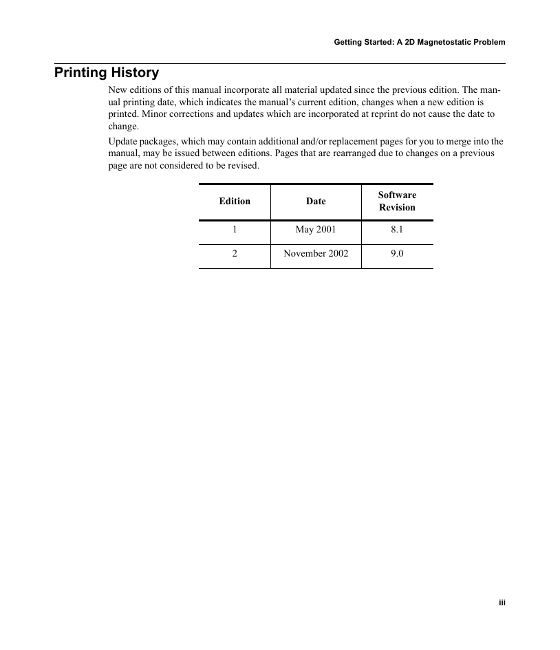
Getting Started: A 2D Magnetostatic Problem Printing History New editions of this manual incorporate all material updated since the previous edition. The man- ual printing date, which indicates the manual’s current edition, changes when a new edition is printed. Minor corrections and updates which are incorporated at reprint do not cause the date to change. Update packages, which may contain additional and/or replacement pages for you to merge into the manual, may be issued between editions. Pages that are rearranged due to changes on a previous page are not considered to be revised. Edition Date 1 2 May 2001 November 2002 Software Revision 8.1 9.0 iii
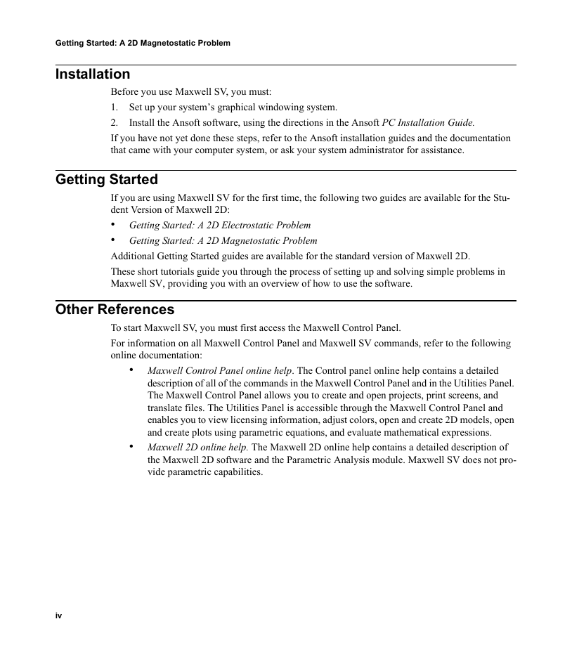
Getting Started: A 2D Magnetostatic Problem Installation Before you use Maxwell SV, you must: 1. Set up your system’s graphical windowing system. 2. If you have not yet done these steps, refer to the Ansoft installation guides and the documentation that came with your computer system, or ask your system administrator for assistance. Install the Ansoft software, using the directions in the Ansoft PC Installation Guide. Getting Started If you are using Maxwell SV for the first time, the following two guides are available for the Stu- dent Version of Maxwell 2D: • Getting Started: A 2D Electrostatic Problem • Getting Started: A 2D Magnetostatic Problem Additional Getting Started guides are available for the standard version of Maxwell 2D. These short tutorials guide you through the process of setting up and solving simple problems in Maxwell SV, providing you with an overview of how to use the software. Other References To start Maxwell SV, you must first access the Maxwell Control Panel. For information on all Maxwell Control Panel and Maxwell SV commands, refer to the following online documentation: • Maxwell Control Panel online help. The Control panel online help contains a detailed description of all of the commands in the Maxwell Control Panel and in the Utilities Panel. The Maxwell Control Panel allows you to create and open projects, print screens, and translate files. The Utilities Panel is accessible through the Maxwell Control Panel and enables you to view licensing information, adjust colors, open and create 2D models, open and create plots using parametric equations, and evaluate mathematical expressions. • Maxwell 2D online help. The Maxwell 2D online help contains a detailed description of the Maxwell 2D software and the Parametric Analysis module. Maxwell SV does not pro- vide parametric capabilities. iv
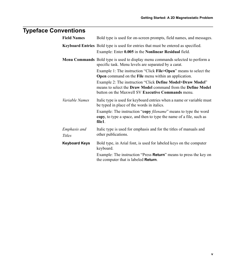
Getting Started: A 2D Magnetostatic Problem Typeface Conventions Field Names Keyboard Entries Bold type is used for entries that must be entered as specified. Bold type is used for on-screen prompts, field names, and messages. Example: Enter 0.005 in the Nonlinear Residual field. Menu Commands Bold type is used to display menu commands selected to perform a Variable Names Emphasis and Titles Keyboard Keys specific task. Menu levels are separated by a carat. Example 1: The instruction “Click File>Open” means to select the Open command on the File menu within an application. Example 2: The instruction “Click Define Model>Draw Model” means to select the Draw Model command from the Define Model button on the Maxwell SV Executive Commands menu. Italic type is used for keyboard entries when a name or variable must be typed in place of the words in italics. Example: The instruction “copy filename” means to type the word copy, to type a space, and then to type the name of a file, such as file1. Italic type is used for emphasis and for the titles of manuals and other publications. Bold type, in Arial font, is used for labeled keys on the computer keyboard. Example: The instruction “Press Return” means to press the key on the computer that is labeled Return. v
Getting Started: A 2D Magnetostatic Problem vi
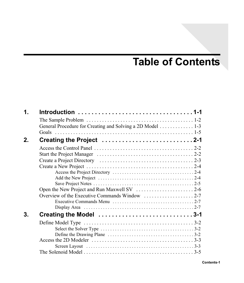
Table of Contents 1. 2. 3. Introduction . . . . . . . . . . . . . . . . . . . . . . . . . . . . . . . . . . 1-1 The Sample Problem . . . . . . . . . . . . . . . . . . . . . . . . . . . . . . . . . . . . . . . . . 1-2 General Procedure for Creating and Solving a 2D Model . . . . . . . . . . . . . 1-3 Goals . . . . . . . . . . . . . . . . . . . . . . . . . . . . . . . . . . . . . . . . . . . . . . . . . . . . . 1-5 Creating the Project . . . . . . . . . . . . . . . . . . . . . . . . . . . 2-1 Access the Control Panel . . . . . . . . . . . . . . . . . . . . . . . . . . . . . . . . . . . . . . 2-2 Start the Project Manager . . . . . . . . . . . . . . . . . . . . . . . . . . . . . . . . . . . . . 2-2 Create a Project Directory . . . . . . . . . . . . . . . . . . . . . . . . . . . . . . . . . . . . 2-3 Create a New Project . . . . . . . . . . . . . . . . . . . . . . . . . . . . . . . . . . . . . . . . . 2-4 Access the Project Directory . . . . . . . . . . . . . . . . . . . . . . . . . . . . . . . . . . 2-4 Add the New Project . . . . . . . . . . . . . . . . . . . . . . . . . . . . . . . . . . . . . . . . 2-4 Save Project Notes . . . . . . . . . . . . . . . . . . . . . . . . . . . . . . . . . . . . . . . . . . 2-5 Open the New Project and Run Maxwell SV . . . . . . . . . . . . . . . . . . . . . . 2-6 Overview of the Executive Commands Window . . . . . . . . . . . . . . . . . . . 2-7 Executive Commands Menu . . . . . . . . . . . . . . . . . . . . . . . . . . . . . . . . . . 2-7 Display Area . . . . . . . . . . . . . . . . . . . . . . . . . . . . . . . . . . . . . . . . . . . . . . 2-7 Creating the Model . . . . . . . . . . . . . . . . . . . . . . . . . . . . 3-1 Define Model Type . . . . . . . . . . . . . . . . . . . . . . . . . . . . . . . . . . . . . . . . . . 3-2 Select the Solver Type . . . . . . . . . . . . . . . . . . . . . . . . . . . . . . . . . . . . . . . 3-2 Define the Drawing Plane . . . . . . . . . . . . . . . . . . . . . . . . . . . . . . . . . . . . 3-2 Access the 2D Modeler . . . . . . . . . . . . . . . . . . . . . . . . . . . . . . . . . . . . . . . 3-3 Screen Layout . . . . . . . . . . . . . . . . . . . . . . . . . . . . . . . . . . . . . . . . . . . . . 3-3 The Solenoid Model . . . . . . . . . . . . . . . . . . . . . . . . . . . . . . . . . . . . . . . . . . 3-5 Contents-1
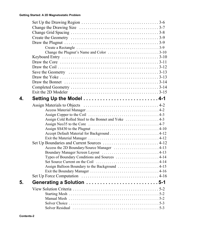
Getting Started: A 2D Magnetostatic Problem Set Up the Drawing Region . . . . . . . . . . . . . . . . . . . . . . . . . . . . . . . . . . . . 3-6 Change the Drawing Size . . . . . . . . . . . . . . . . . . . . . . . . . . . . . . . . . . . . . 3-7 Change Grid Spacing . . . . . . . . . . . . . . . . . . . . . . . . . . . . . . . . . . . . . . . . . 3-8 Create the Geometry . . . . . . . . . . . . . . . . . . . . . . . . . . . . . . . . . . . . . . . . . 3-9 Draw the Plugnut . . . . . . . . . . . . . . . . . . . . . . . . . . . . . . . . . . . . . . . . . . . . 3-9 Create a Rectangle . . . . . . . . . . . . . . . . . . . . . . . . . . . . . . . . . . . . . . . . . . 3-9 Change the Plugnut’s Name and Color . . . . . . . . . . . . . . . . . . . . . . . . . . 3-10 Keyboard Entry . . . . . . . . . . . . . . . . . . . . . . . . . . . . . . . . . . . . . . . . . . . . . 3-10 Draw the Core . . . . . . . . . . . . . . . . . . . . . . . . . . . . . . . . . . . . . . . . . . . . . . 3-11 Draw the Coil . . . . . . . . . . . . . . . . . . . . . . . . . . . . . . . . . . . . . . . . . . . . . . . 3-12 Save the Geometry . . . . . . . . . . . . . . . . . . . . . . . . . . . . . . . . . . . . . . . . . . 3-13 Draw the Yoke . . . . . . . . . . . . . . . . . . . . . . . . . . . . . . . . . . . . . . . . . . . . . . 3-13 Draw the Bonnet . . . . . . . . . . . . . . . . . . . . . . . . . . . . . . . . . . . . . . . . . . . . 3-14 Completed Geometry . . . . . . . . . . . . . . . . . . . . . . . . . . . . . . . . . . . . . . . . . 3-14 Exit the 2D Modeler . . . . . . . . . . . . . . . . . . . . . . . . . . . . . . . . . . . . . . . . . 3-15 Setting Up the Model . . . . . . . . . . . . . . . . . . . . . . . . . . . 4-1 Assign Materials to Objects . . . . . . . . . . . . . . . . . . . . . . . . . . . . . . . . . . . 4-2 Access Material Manager . . . . . . . . . . . . . . . . . . . . . . . . . . . . . . . . . . . . . 4-2 Assign Copper to the Coil . . . . . . . . . . . . . . . . . . . . . . . . . . . . . . . . . . . . 4-3 Assign Cold Rolled Steel to the Bonnet and Yoke . . . . . . . . . . . . . . . . . 4-3 Assign Neo35 to the Core . . . . . . . . . . . . . . . . . . . . . . . . . . . . . . . . . . . . 4-7 Assign SS430 to the Plugnut . . . . . . . . . . . . . . . . . . . . . . . . . . . . . . . . . . 4-10 Accept Default Material for Background . . . . . . . . . . . . . . . . . . . . . . . . . 4-12 Exit the Material Manager . . . . . . . . . . . . . . . . . . . . . . . . . . . . . . . . . . . . 4-12 Set Up Boundaries and Current Sources . . . . . . . . . . . . . . . . . . . . . . . . . . 4-12 Access the 2D Boundary/Source Manager . . . . . . . . . . . . . . . . . . . . . . . 4-13 Boundary Manager Screen Layout . . . . . . . . . . . . . . . . . . . . . . . . . . . . . 4-13 Types of Boundary Conditions and Sources . . . . . . . . . . . . . . . . . . . . . . 4-14 Set Source Current on the Coil . . . . . . . . . . . . . . . . . . . . . . . . . . . . . . . . 4-14 Assign Balloon Boundary to the Background . . . . . . . . . . . . . . . . . . . . . 4-15 Exit the Boundary Manager . . . . . . . . . . . . . . . . . . . . . . . . . . . . . . . . . . . 4-16 Set Up Force Computation . . . . . . . . . . . . . . . . . . . . . . . . . . . . . . . . . . . . 4-16 Generating a Solution . . . . . . . . . . . . . . . . . . . . . . . . . . 5-1 View Solution Criteria . . . . . . . . . . . . . . . . . . . . . . . . . . . . . . . . . . . . . . . . 5-2 Starting Mesh . . . . . . . . . . . . . . . . . . . . . . . . . . . . . . . . . . . . . . . . . . . . . . 5-2 Manual Mesh . . . . . . . . . . . . . . . . . . . . . . . . . . . . . . . . . . . . . . . . . . . . . . 5-2 Solver Choice . . . . . . . . . . . . . . . . . . . . . . . . . . . . . . . . . . . . . . . . . . . . . . 5-3 Solver Residual . . . . . . . . . . . . . . . . . . . . . . . . . . . . . . . . . . . . . . . . . . . . 5-3 4. 5. Contents-2
分享到:
收藏