ANSI/VITA 57.1-2008 - Revisions Under Consideration
The VITA 57.1 working group is considering the following changes to ANSI/VITA
57.1-2008 that would affect compliance and interoperability. NOTE: This
information is provided for information only. While the working group is currently
considering these changes, they may or may not be approved by the working
group and may or may not become part of a revised standard. Contact VITA for
more information. October 2008.
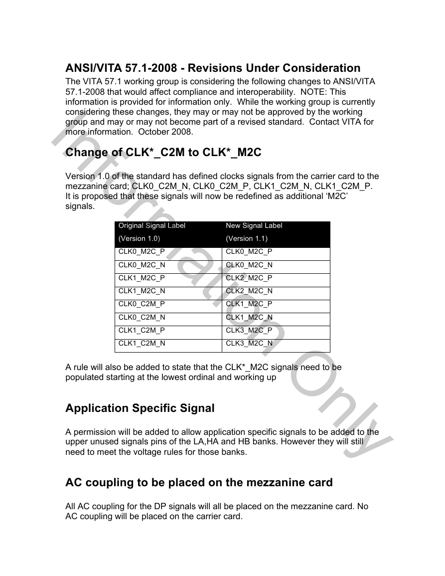
Change of CLK*_C2M to CLK*_M2C
Version 1.0 of the standard has defined clocks signals from the carrier card to the
mezzanine card; CLK0_C2M_N, CLK0_C2M_P, CLK1_C2M_N, CLK1_C2M_P.
It is proposed that these signals will now be redefined as additional ‘M2C’
signals.
Original Signal Label
(Version 1.0)
CLK0_M2C_P
CLK0_M2C_N
CLK1_M2C_P
CLK1_M2C_N
CLK0_C2M_P
CLK0_C2M_N
CLK1_C2M_P
CLK1_C2M_N
New Signal Label
(Version 1.1)
CLK0_M2C_P
CLK0_M2C_N
CLK2_M2C_P
CLK2_M2C_N
CLK1_M2C_P
CLK1_M2C_N
CLK3_M2C_P
CLK3_M2C_N
A rule will also be added to state that the CLK*_M2C signals need to be
populated starting at the lowest ordinal and working up
Application Specific Signal
A permission will be added to allow application specific signals to be added to the
upper unused signals pins of the LA,HA and HB banks. However they will still
need to meet the voltage rules for those banks.
AC coupling to be placed on the mezzanine card
All AC coupling for the DP signals will all be placed on the mezzanine card. No
AC coupling will be placed on the carrier card.
Information Only�
ANSI/VITA 57.1-2008
American National Standard
for FPGA Mezzanine Card (FMC)
Standard
Secretariat
VMEbus International Trade Association
Approved July 2008
American National Standards Institute, Inc.
VMEbus International Trade Association
PO Box 19658, Fountain Hills, AZ 85269
PH: 480-837-7486, FAX: Contact VITA Office
E-mail: info@vita.com, URL: http://www.vita.com
�
(This page left blank intentionally.)
�
ANSI/VITA 57.1-2008
American National Standard
for FPGA Mezzanine Card
(FMC) Standard
Secretariat
VMEbus International Trade Association
Approved July 2008
American National Standards Institute, Inc.
Abstract
This standard specifies a form factor and a pin assignment for FPGA
mezzanine modules.
�
American
National
Standard
Approval of an American National Standard requires
verification by ANSI that the requirements for due process,
consensus, and other criteria for approval have been met
by the standards developer.
Consensus is established when, in the judgment of the
ANSI Board of Standards Review, substantial agreement
has been reached by directly and materially affected
interests. Substantial agreement means much more than
a simple majority, but not necessarily unanimity.
Consensus requires that all views and objections be
considered, and that a concerted effort be made toward
their resolution.
The use of American National Standards is completely
voluntary; their existence does not in any respect preclude
anyone, whether he has approved the standards or not,
from manufacturing, marketing, purchasing, or using
products, processes, or procedures not conforming to the
standards.
The American National Standards Institute does not
develop standards and will in no circumstances give an
interpretation of any American National Standard.
Moreover, no person shall have the right or authority to
issue an interpretation of an American National Standard
in the name of the American National Standard Institute.
Requests for interpretations should be addressed to the
secretariat or sponsor whose name appears on the title
page of this standard.
CAUTION NOTICE: This American National Standard may
be revised or withdrawn at any time. The procedures of
the American National Standards Institute require that
action be taken periodically to reaffirm, revise, or withdraw
this standard. Purchases of American National Standards
may receive current information on all standard by calling
or writing the American National Standards Institute.
Published by
VMEbus International Trade Association
PO Box 19658, Fountain Hills, AZ 85269
Copyright © 2008 by VMEbus International Trade Association
All rights reserved.
No part of this publication may be reproduced in any form, in an electronic
retrieval system or otherwise, without prior written permission of the
publisher.
Printed in the United States of America - R1.0, ISBN 1-885731-49-3
�
ANSI/VITA 57.1, FPGA Mezzanine Card (FMC) Standard
TABLE OF CONTENTS
1
2
3
2.1.
2.2.
3.4.1.
3.4.2.
3.4.3.
3.4.4.
Introduction ...............................................................................................................11
1.1. Objectives..........................................................................................................11
FMC Overview..................................................................................................12
1.2.
Standard Terminology.......................................................................................12
1.3.
1.4.
FMC Definitions ..............................................................................................14
1.5. References .........................................................................................................15
1.6. Dimensions........................................................................................................15
FMC Compliance ......................................................................................................16
FMC Mezzanine Module’s Minimum Features................................................16
FMC Carrier Card’s Minimum Features...........................................................16
FMC Mezzanine Module ..........................................................................................17
3.1. Overview ...........................................................................................................17
3.2.
Single Width Mezzanine Module......................................................................20
3.3. Double Width Mezzanine Module ....................................................................21
3.4. Connectors.........................................................................................................24
Variable stacking heights ..........................................................................25
Ground connections...................................................................................27
Connector Pads and Labeling....................................................................27
Connector Assembly .................................................................................28
3.5. Conduction Cooled Mezzanine Modules ..........................................................29
Single Width Module ................................................................................29
Double Width Module...............................................................................32
Conduction Cooled....................................................................................34
Thermal Interfaces.....................................................................................34
Air cooled and conduction cooled compatibility ......................................35
FMC Front Panel Bezel.....................................................................................37
3.6.1.
FMC Mezzanine Module to Carrier Card relationship .............................39
FMC Carrier Card .....................................................................................................40
4.1. Overview ...........................................................................................................40
Carrier Card side 1 component height.......................................................46
5 Connector Pin Assignments ......................................................................................48
5.1. User Defined Pins..............................................................................................53
5.2. Differential Reference Clocks...........................................................................56
5.3. Gigabit Interface................................................................................................58
Gigabit Data Signals..................................................................................58
Gigabit reference clocks............................................................................60
JTAG Signals ....................................................................................................61
I2C Bus Signals.................................................................................................62
IPMI Support.............................................................................................63
5.6. Geographic Addresses.......................................................................................66
5.7.
IO Mezzanine Module Present..........................................................................67
5.8.
Power Good Signals..........................................................................................67
5.9. Reserved Signals ...............................................................................................68
3.5.1.
3.5.2.
3.5.3.
3.5.4.
3.5.5.
5.3.1.
5.3.2.
5.4.
5.5.
5.5.1.
3.6.
4
4.1.1.
Page 5
�
ANSI/VITA 57.1, FPGA Mezzanine Card (FMC) Standard
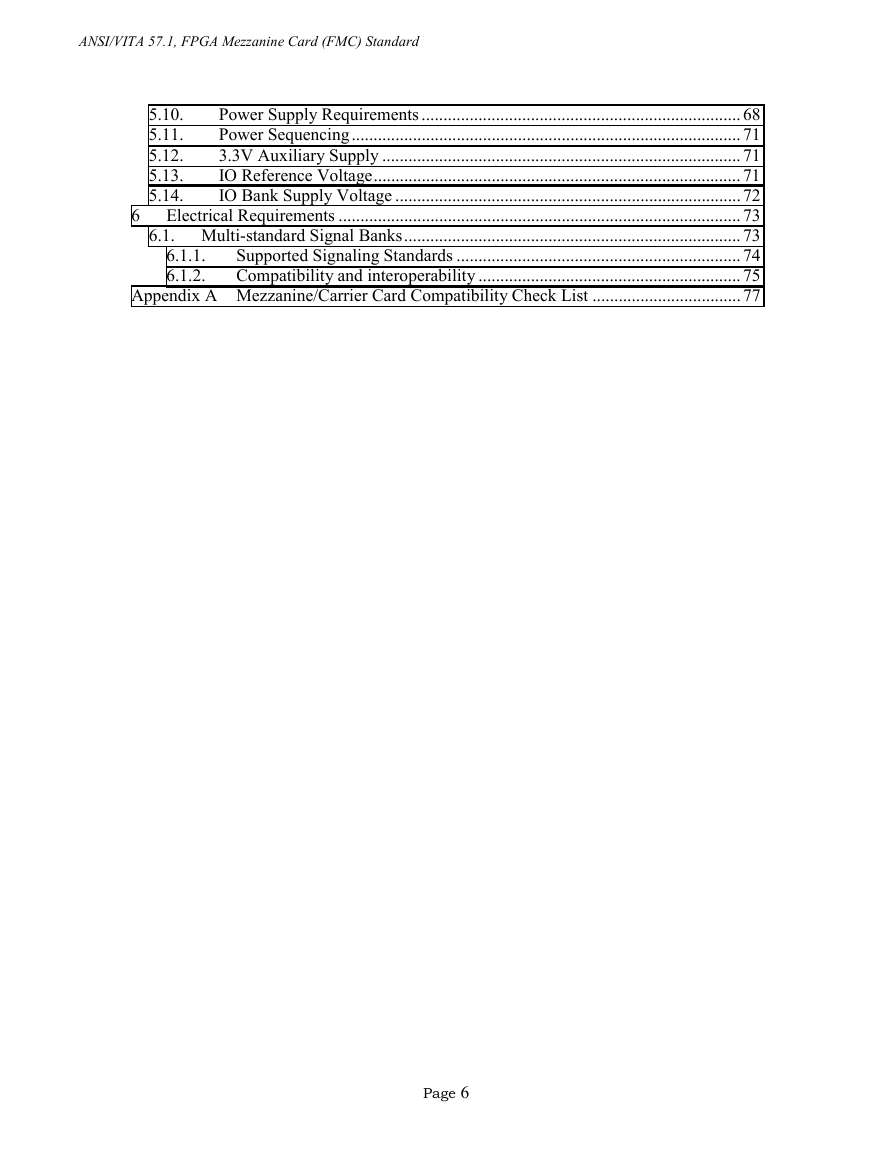
5.10.
5.11.
5.12.
5.13.
5.14.
Power Supply Requirements .........................................................................68
Power Sequencing.........................................................................................71
3.3V Auxiliary Supply ..................................................................................71
IO Reference Voltage....................................................................................71
IO Bank Supply Voltage ...............................................................................72
Electrical Requirements ............................................................................................73
6.1. Multi-standard Signal Banks.............................................................................73
Supported Signaling Standards .................................................................74
Compatibility and interoperability ............................................................75
Appendix A Mezzanine/Carrier Card Compatibility Check List ..................................77
6
6.1.1.
6.1.2.
Page 6
�
ANSI/VITA 57.1, FPGA Mezzanine Card (FMC) Standard
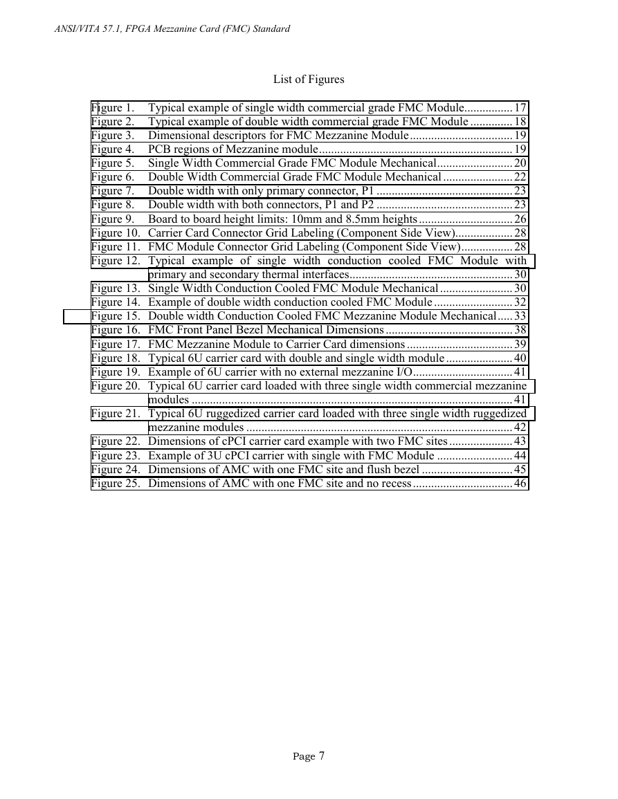
List of Figures
Figure 1. Typical example of single width commercial grade FMC Module................17
Figure 2. Typical example of double width commercial grade FMC Module ..............18
Figure 3. Dimensional descriptors for FMC Mezzanine Module..................................19
Figure 4. PCB regions of Mezzanine module................................................................19
Figure 5. Single Width Commercial Grade FMC Module Mechanical.........................20
Figure 6. Double Width Commercial Grade FMC Module Mechanical .......................22
Figure 7. Double width with only primary connector, P1 .............................................23
Figure 8. Double width with both connectors, P1 and P2 .............................................23
Figure 9. Board to board height limits: 10mm and 8.5mm heights...............................26
Figure 10. Carrier Card Connector Grid Labeling (Component Side View)...................28
Figure 11. FMC Module Connector Grid Labeling (Component Side View).................28
Figure 12. Typical example of single width conduction cooled FMC Module with
primary and secondary thermal interfaces......................................................30
Figure 13. Single Width Conduction Cooled FMC Module Mechanical........................30
Figure 14. Example of double width conduction cooled FMC Module ..........................32
Figure 15. Double width Conduction Cooled FMC Mezzanine Module Mechanical.....33
Figure 16. FMC Front Panel Bezel Mechanical Dimensions ..........................................38
Figure 17. FMC Mezzanine Module to Carrier Card dimensions ...................................39
Figure 18. Typical 6U carrier card with double and single width module ......................40
Figure 19. Example of 6U carrier with no external mezzanine I/O.................................41
Figure 20. Typical 6U carrier card loaded with three single width commercial mezzanine
modules ..........................................................................................................41
Figure 21. Typical 6U ruggedized carrier card loaded with three single width ruggedized
mezzanine modules ........................................................................................42
Figure 22. Dimensions of cPCI carrier card example with two FMC sites.....................43
Figure 23. Example of 3U cPCI carrier with single with FMC Module .........................44
Figure 24. Dimensions of AMC with one FMC site and flush bezel ..............................45
Figure 25. Dimensions of AMC with one FMC site and no recess.................................46
Page 7
�




 2023年江西萍乡中考道德与法治真题及答案.doc
 2012年重庆南川中考生物真题及答案.doc
 2013年江西师范大学地理学综合及文艺理论基础考研真题.doc
 2020年四川甘孜小升初语文真题及答案I卷.doc
 2020年注册岩土工程师专业基础考试真题及答案.doc
 2023-2024学年福建省厦门市九年级上学期数学月考试题及答案.doc
 2021-2022学年辽宁省沈阳市大东区九年级上学期语文期末试题及答案.doc
 2022-2023学年北京东城区初三第一学期物理期末试卷及答案.doc
 2018上半年江西教师资格初中地理学科知识与教学能力真题及答案.doc
 2012年河北国家公务员申论考试真题及答案-省级.doc
 2020-2021学年江苏省扬州市江都区邵樊片九年级上学期数学第一次质量检测试题及答案.doc
 2022下半年黑龙江教师资格证中学综合素质真题及答案.doc