PR440FX Motherboard Technical Product Specification
Disclaimer
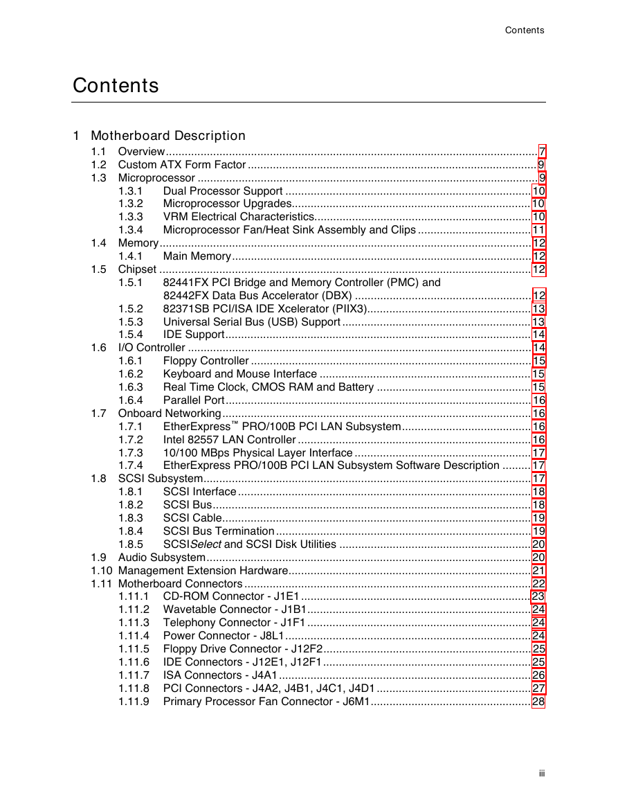
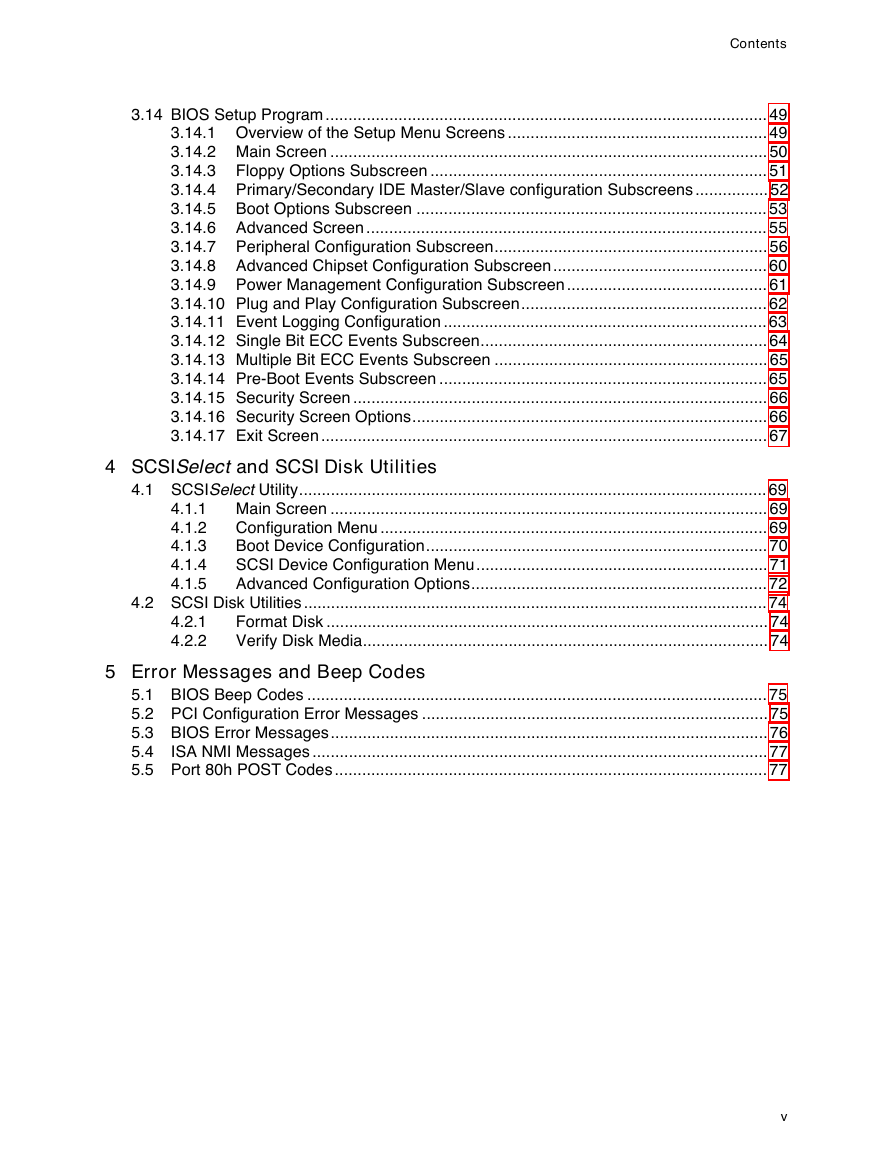
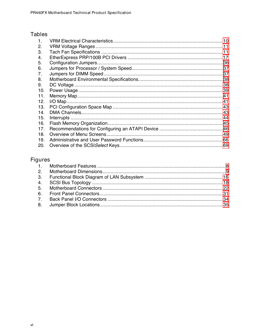
Contents
1 PR440FX Motherboard Technical Product Specification
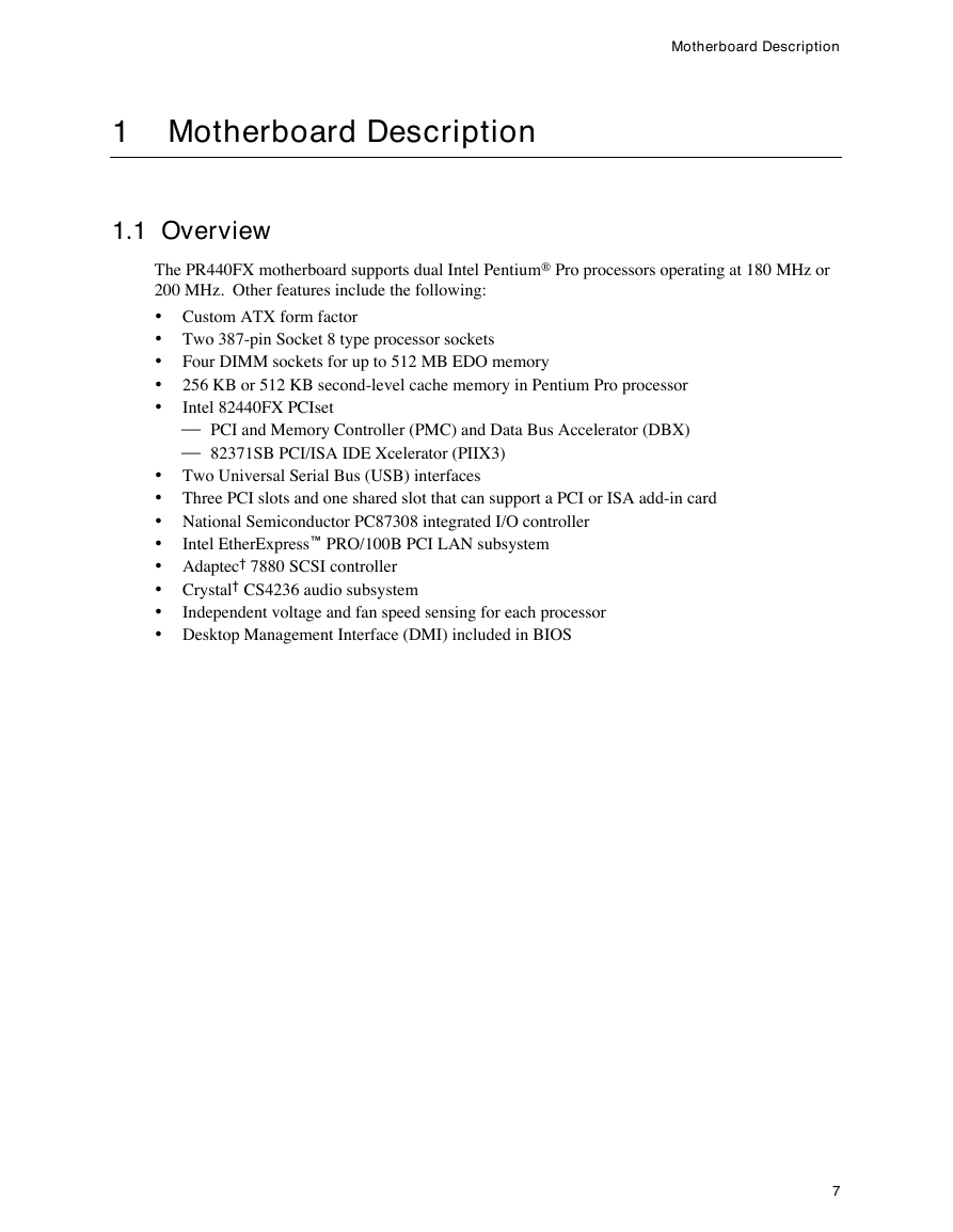
1.1 Overview
1.2 Custom ATX Form Factor
1.3 Microprocessor
1.3.1 Dual Processor Support
1.3.2 Microprocessor Upgrades
1.3.3 VRM Electrical Characteristics
1.3.4 Microprocessor Fan/Heat Sink Assembly and Clips
1.4 Memory
1.4.1 Main Memory
1.5 Chipset
1.5.1 82441FX PCI Bridge and Memory Controller (PMC) and 82442FX Data Bus Accelerator (DBX)
1.5.2 82371SB PCI/ISA IDE Xcelerator (PIIX3)
1.5.3 Universal Serial Bus (USB) Support
1.5.4 IDE Support
1.6 I/O Controller
1.6.1 Floppy Controller
1.6.2 Keyboard and Mouse Interface
1.6.3 Real Time Clock, CMOS RAM and Battery
1.6.4 Parallel Port
1.7 Onboard Networking
1.7.1 EtherExpress ™ PRO/100B PCI LAN Subsystem
1.7.2 Intel 82557 LAN Controller
1.7.3 10/100 MBps Physical Layer Interface
1.7.4 EtherExpress PRO/100B PCI LAN Subsystem Software Description
1.8 SCSI Subsystem
1.8.1 SCSI Interface
1.8.2 SCSI Bus
1.8.3 SCSI Cable
1.8.4 SCSI Bus Termination
1.8.5 SCSI Select and SCSI Disk Utilities
1.9 Audio Subsystem
1.10 Management Extension Hardware
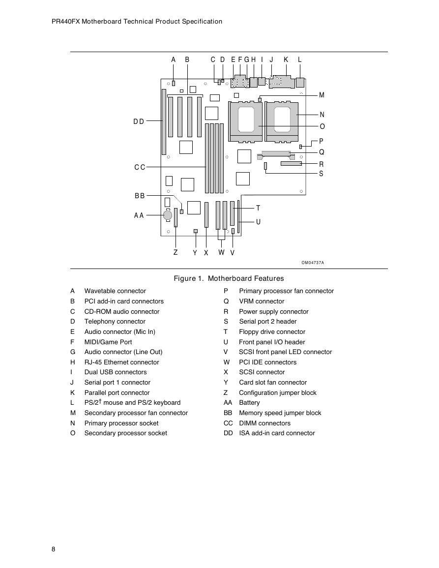
1.11 Motherboard Connectors
1.11.1 CD-ROM Connector - J1E1
1.11.2 Wavetable Connector - J1B1
1.11.3 Telephony Connector - J1F1
1.11.4 Power Connector - J8L1
1.11.5 Floppy Drive Connector - J12F2
1.11.6 IDE Connectors - J12E1, J12F1
1.11.7 ISA Connectors - J4A1
1.11.8 PCI Connectors - J4A2, J4B1, J4C1, J4D1
1.11.9 Primary Processor Fan Connector - J6M1
1.11.10 Secondary Processor Fan Connector - J2J1
1.11.11 Card Slot Fan Connector - J13C1
1.11.12 SCSI Hard Drive Front Panel LED Connector LED - J13G1
1.11.13 VRM Connector - J7K1
1.11.14 Serial Port 2 Header - J8J1
1.11.15 SCSI Connector - J12D1
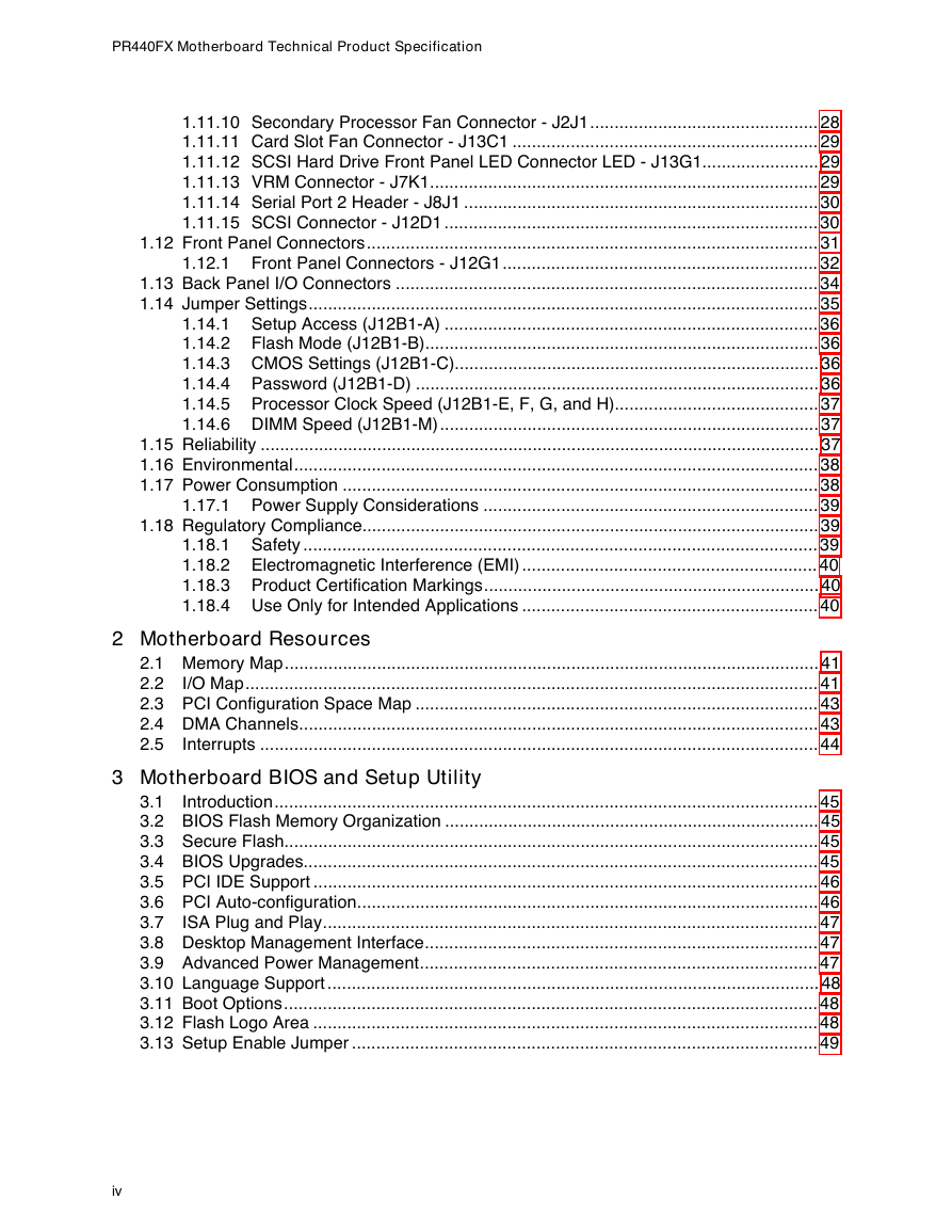
1.12 Front Panel Connectors
1.12.1 Front Panel Connectors - J12G1
1.13 Back Panel I/O Connectors
1.14 Jumper Settings
1.14.1 Setup Access (J12B1-A)
1.14.2 Flash Mode (J12B1-B)
1.14.3 CMOS Settings (J12B1-C)
1.14.4 Password (J12B1-D)
1.14.5 Processor Clock Speed (J12B1-E, F, G, and H)
1.14.6 DIMM Speed (J12B1-M)
1.15 Reliability
1.16 Environmental
1.17 Power Consumption
1.17.1 Power Supply Considerations
1.18 Regulatory Compliance
1.18.1 Safety
1.18.2 Electromagnetic Interference (EMI)
1.18.3 Product Certification Markings
1.18.4 Use Only for Intended Applications
2 Motherboard Resources
2.1 Memory Map
2.2 I/O Map
2.3 PCI Configuration Space Map
2.4 DMA Channels
2.5 Interrupts
3 Motherboard BIOS and Setup Utility
3.1 Introduction
3.2 BIOS Flash Memory Organization
3.3 Secure Flash
3.4 BIOS Upgrades
3.5 PCI IDE Support
3.6 PCI Auto-configuration
3.7 ISA Plug and Play
3.8 Desktop Management Interface
3.9 Advanced Power Management
3.10 Language Support
3.11 Boot Options
3.12 Flash Logo Area
3.13 Setup Enable Jumper
3.14 BIOS Setup Program
3.14.1 Overview of the Setup Menu Screens
3.14.2 Main Screen
3.14.3 Floppy Options Subscreen
3.14.4 Primary/Secondary IDE Master/Slave configuration Subscreens
3.14.5 Boot Options Subscreen
3.14.6 Advanced Screen
3.14.7 Peripheral Configuration Subscreen
3.14.8 Advanced Chipset Configuration Subscreen
3.14.9 Power Management Configuration Subscreen
3.14.10 Plug and Play Configuration Subscreen
3.14.11 Event Logging Configuration
3.14.12 Single Bit ECC Events Subscreen
3.14.13 Multiple Bit ECC Events Subscreen
3.14.14 Pre-Boot Events Subscreen
3.14.15 Security Screen
3.14.16 Security Screen Options
3.14.17 Exit Screen
4 SCSI Select and SCSI Disk Utilities
4.1 SCSI Select Utility
4.1.1 Main Screen
4.1.2 Configuration Menu
4.1.3 Boot Device Configuration
4.1.4 SCSI Device Configuration Menu
4.1.5 Advanced Configuration Options
4.2 SCSI Disk Utilities
4.2.1 Format Disk
4.2.2 Verify Disk Media
5 Error Messages and Beep Codes
5.1 BIOS Beep Codes
5.2 PCI Configuration Error Messages
5.3 BIOS Error Messages
5.4 ISA NMI Messages
5.5 Port 80h POST Codes


 2023年江西萍乡中考道德与法治真题及答案.doc
 2012年重庆南川中考生物真题及答案.doc
 2013年江西师范大学地理学综合及文艺理论基础考研真题.doc
 2020年四川甘孜小升初语文真题及答案I卷.doc
 2020年注册岩土工程师专业基础考试真题及答案.doc
 2023-2024学年福建省厦门市九年级上学期数学月考试题及答案.doc
 2021-2022学年辽宁省沈阳市大东区九年级上学期语文期末试题及答案.doc
 2022-2023学年北京东城区初三第一学期物理期末试卷及答案.doc
 2018上半年江西教师资格初中地理学科知识与教学能力真题及答案.doc
 2012年河北国家公务员申论考试真题及答案-省级.doc
 2020-2021学年江苏省扬州市江都区邵樊片九年级上学期数学第一次质量检测试题及答案.doc
 2022下半年黑龙江教师资格证中学综合素质真题及答案.doc