�
OFDMSynchronizationExample.m
Copyright 2013-2014 The MathWorks, Inc.
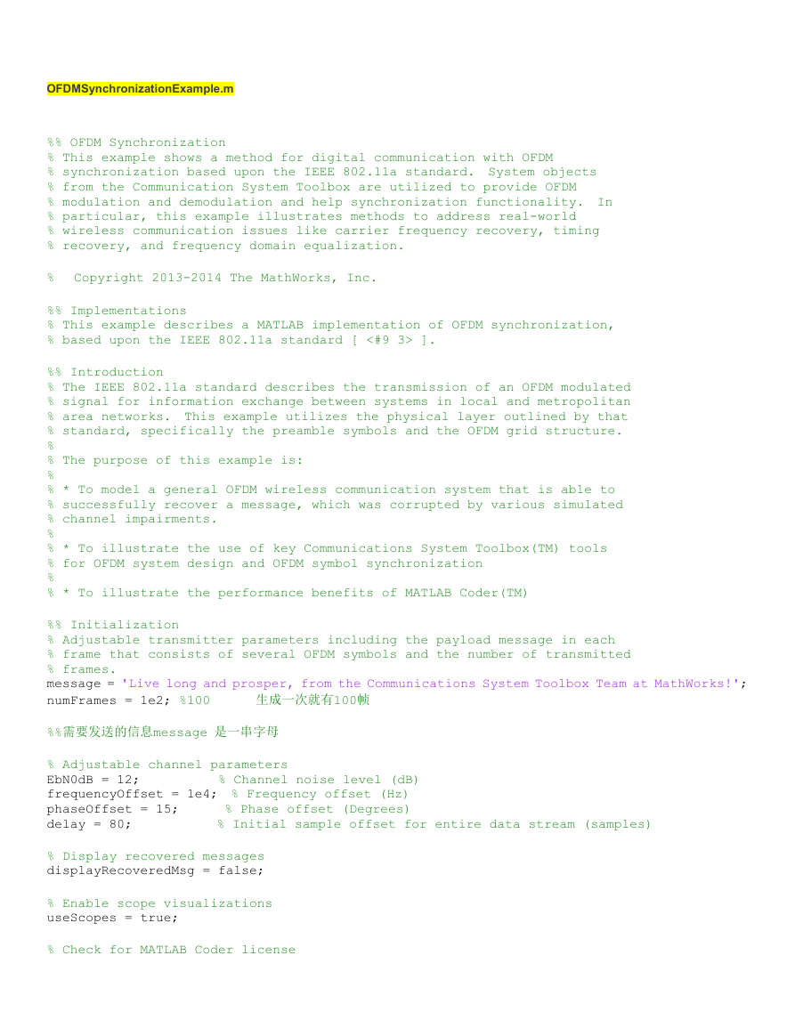
%% OFDM Synchronization
% This example shows a method for digital communication with OFDM
% synchronization based upon the IEEE 802.11a standard. System objects
% from the Communication System Toolbox are utilized to provide OFDM
% modulation and demodulation and help synchronization functionality. In
% particular, this example illustrates methods to address real-world
% wireless communication issues like carrier frequency recovery, timing
% recovery, and frequency domain equalization.
%
%% Implementations
% This example describes a MATLAB implementation of OFDM synchronization,
% based upon the IEEE 802.11a standard [ <#9 3> ].
%% Introduction
% The IEEE 802.11a standard describes the transmission of an OFDM modulated
% signal for information exchange between systems in local and metropolitan
% area networks. This example utilizes the physical layer outlined by that
% standard, specifically the preamble symbols and the OFDM grid structure.
%
% The purpose of this example is:
%
% * To model a general OFDM wireless communication system that is able to
% successfully recover a message, which was corrupted by various simulated
% channel impairments.
%
% * To illustrate the use of key Communications System Toolbox(TM) tools
% for OFDM system design and OFDM symbol synchronization
%
% * To illustrate the performance benefits of MATLAB Coder(TM)
%% Initialization
% Adjustable transmitter parameters including the payload message in each
% frame that consists of several OFDM symbols and the number of transmitted
% frames.
message = 'Live long and prosper, from the Communications System Toolbox Team at MathWorks!';
numFrames = 1e2; %100
%%需要发送的信息message 是一串字母
% Adjustable channel parameters
% Channel noise level (dB)
EbN0dB = 12;
frequencyOffset = 1e4; % Frequency offset (Hz)
phaseOffset = 15;
% Phase offset (Degrees)
delay = 80;
% Initial sample offset for entire data stream (samples)
% Display recovered messages
displayRecoveredMsg = false;
% Enable scope visualizations
useScopes = true;
% Check for MATLAB Coder license
生成一次就有100帧
useCodegen = checkCodegenLicenseOFDM;
% By default the transmitter and receiver functions will be recompiled
% between every run, which is not always necessary. To disable receiver
% compilation, change "compileIt" to false.
compileIt = useCodegen;
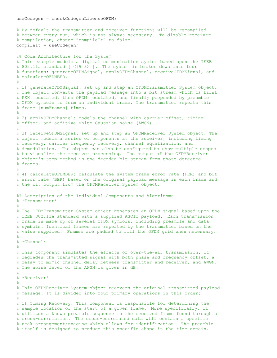
%% Code Architecture for the System
% This example models a digital communication system based upon the IEEE
% 802.11a standard [ <#9 3> ]. The system is broken down into four
% functions: generateOFDMSignal, applyOFDMChannel, receiveOFDMSignal, and
% calculateOFDMBER.
%
% 1) generateOFDMSignal: set up and step an OFDMTransmitter System object.
% The object converts the payload message into a bit stream which is first
% PSK modulated, then OFDM modulated, and finally prepended by preamble
% OFDM symbols to form an individual frame. The transmitter repeats this
% frame |numFrames| times.
%
% 2) applyOFDMChannel: models the channel with carrier offset, timing
% offset, and additive white Gaussian noise (AWGN).
%
% 3) receiveOFDMSignal: set up and step an OFDMReceiver System object. The
% object models a series of components at the receiver, including timing
% recovery, carrier frequency recovery, channel equalization, and
% demodulation. The object can also be configured to show multiple scopes
% to visualize the receiver processing. The output of the OFDMReceiver
% object's step method is the decoded bit stream from those detected
% frames.
%
% 4) calculateOFDMBER: calculate the system frame error rate (FER) and bit
% error rate (BER) based on the original payload message in each frame and
% the bit output from the OFDMReceiver System object.
%% Description of the Individual Components and Algorithms
% *Transmitter*
%
% The OFDMTransmitter System object generates an OFDM signal based upon the
% IEEE 802.11a standard with a supplied ASCII payload. Each transmission
% frame is made up of several OFDM symbols, including preamble and data
% symbols. Identical frames are repeated by the transmitter based on the
% value supplied. Frames are padded to fill the OFDM grid when necessary.
%
% *Channel*
%
% This component simulates the effects of over-the-air transmission. It
% degrades the transmitted signal with both phase and frequency offset, a
% delay to mimic channel delay between transmitter and receiver, and AWGN.
% The noise level of the AWGN is given in dB.
%
% *Receiver*
%
% This OFDMReceiver System object recovers the original transmitted payload
% message. It is divided into four primary operations in this order:
%
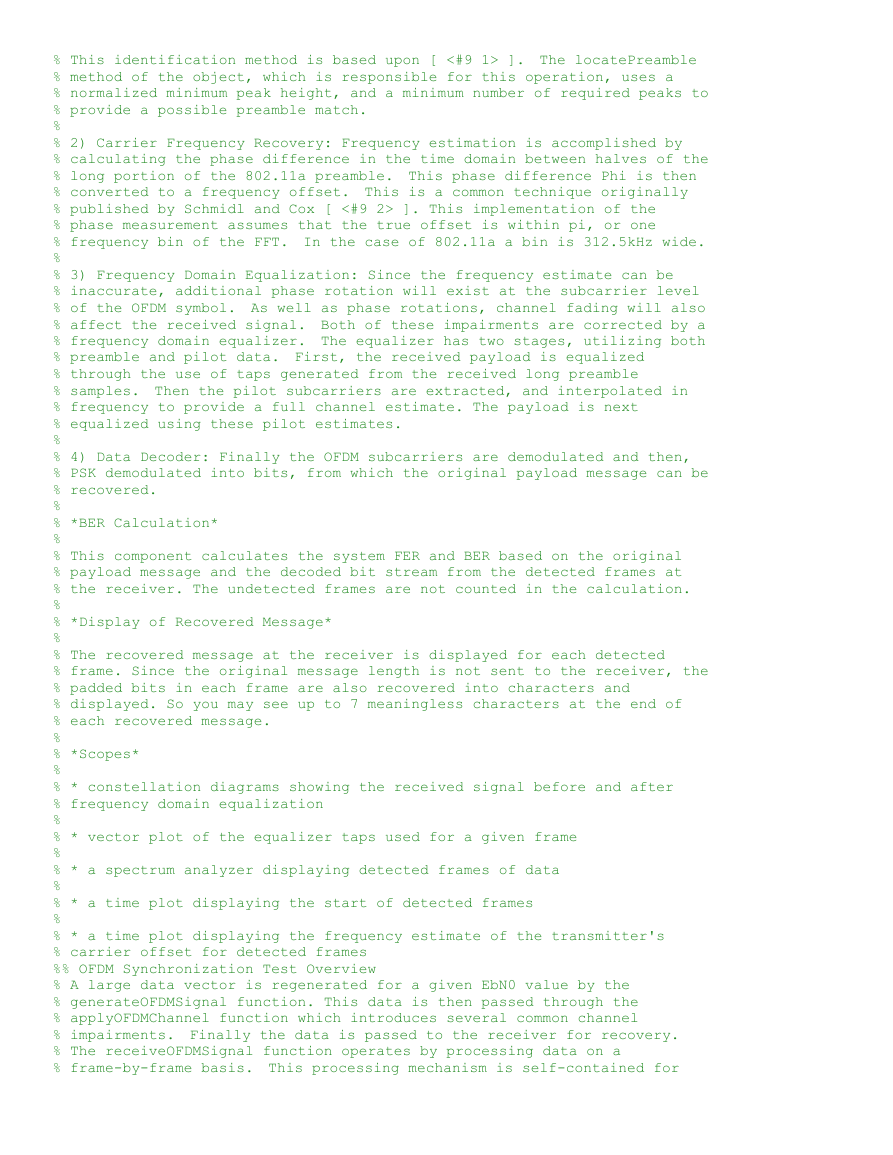
% 1) Timing Recovery: This component is responsible for determining the
% sample location of the start of a given frame. More specifically, it
% utilizes a known preamble sequence in the received frame found through a
% cross-correlation. The cross-correlated data will contain a specific
% peak arrangement/spacing which allows for identification. The preamble
% itself is designed to produce this specific shape in the time domain.
�
% This identification method is based upon [ <#9 1> ]. The locatePreamble
% method of the object, which is responsible for this operation, uses a
% normalized minimum peak height, and a minimum number of required peaks to
% provide a possible preamble match.
%
% 2) Carrier Frequency Recovery: Frequency estimation is accomplished by
% calculating the phase difference in the time domain between halves of the
% long portion of the 802.11a preamble. This phase difference Phi is then
% converted to a frequency offset. This is a common technique originally
% published by Schmidl and Cox [ <#9 2> ]. This implementation of the
% phase measurement assumes that the true offset is within pi, or one
% frequency bin of the FFT. In the case of 802.11a a bin is 312.5kHz wide.
%
% 3) Frequency Domain Equalization: Since the frequency estimate can be
% inaccurate, additional phase rotation will exist at the subcarrier level
% of the OFDM symbol. As well as phase rotations, channel fading will also
% affect the received signal. Both of these impairments are corrected by a
% frequency domain equalizer. The equalizer has two stages, utilizing both
% preamble and pilot data. First, the received payload is equalized
% through the use of taps generated from the received long preamble
% samples. Then the pilot subcarriers are extracted, and interpolated in
% frequency to provide a full channel estimate. The payload is next
% equalized using these pilot estimates.
%
% 4) Data Decoder: Finally the OFDM subcarriers are demodulated and then,
% PSK demodulated into bits, from which the original payload message can be
% recovered.
%
% *BER Calculation*
%
% This component calculates the system FER and BER based on the original
% payload message and the decoded bit stream from the detected frames at
% the receiver. The undetected frames are not counted in the calculation.
%
% *Display of Recovered Message*
%
% The recovered message at the receiver is displayed for each detected
% frame. Since the original message length is not sent to the receiver, the
% padded bits in each frame are also recovered into characters and
% displayed. So you may see up to 7 meaningless characters at the end of
% each recovered message.
%
% *Scopes*
%
% * constellation diagrams showing the received signal before and after
% frequency domain equalization
%
% * vector plot of the equalizer taps used for a given frame
%
% * a spectrum analyzer displaying detected frames of data
%
% * a time plot displaying the start of detected frames
%
% * a time plot displaying the frequency estimate of the transmitter's
% carrier offset for detected frames
%% OFDM Synchronization Test Overview
% A large data vector is regenerated for a given EbN0 value by the
% generateOFDMSignal function. This data is then passed through the
% applyOFDMChannel function which introduces several common channel
% impairments. Finally the data is passed to the receiver for recovery.
% The receiveOFDMSignal function operates by processing data on a
% frame-by-frame basis. This processing mechanism is self-contained for
�
% performance benefits when using code generation and for code simplicity.
% This script by default generates code for the transmitter and receiver
% functions; this is accomplished by using the *codegen* command provided
% by the MATLAB Coder(TM) product. The *codegen* command translates
% MATLAB(R) functions to a C++ static or dynamic library, executable, or to
% a MEX file, producing a code for accelerated execution. The generated C
% code runs several times faster than the original MATLAB code.
%
% During operation, the receiver will display a series of plots
% illustrating certain synchronization results and effects on the signal.
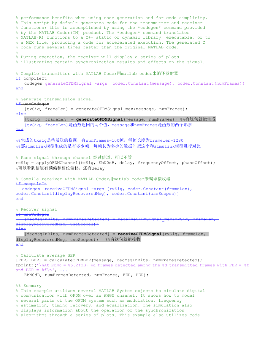
codegen generateOFDMSignal -args {coder.Constant(message), coder.Constant(numFrames)}
% Compile transmitter with MATLAB Coder用matlab coder来编译发射器
if compileIt
end
% Generate transmission signal
if useCodegen
else
[txSig, frameLen] = generateOFDMSignal_mex(message, numFrames);
[txSig, frameLen] = generateOFDMSignal(message, numFrames); %%有这句就能生成
[txSig, frameLen]是函数返回的两个值,message和numFrames是函数的两个形参
End
%%生成的txsig是待发送的数据,有numFrames=100帧,每帧长度为framelen=1280
%%那simulink模型生成的是有多少帧,每帧长为多少的数据?把这个和simulink模型进行对比
codegen receiveOFDMSignal -args {rxSig, coder.Constant(frameLen),
% Pass signal through channel 经过信道,可以不管
rxSig = applyOFDMChannel(txSig, EbN0dB, delay, frequencyOffset, phaseOffset);
%可以看到信道有频偏和相位偏移,还有delay
% Compile receiver with MATLAB Coder用matlab coder来编译接收器
if compileIt
coder.Constant(displayRecoveredMsg), coder.Constant(useScopes)}
end
% Recover signal
if useCodegen
displayRecoveredMsg, useScopes);
else
displayRecoveredMsg, useScopes);
end
% Calculate average BER
[FER, BER] = calculateOFDMBER(message, decMsgInBits, numFramesDetected);
fprintf('\nAt EbNo = %5.2fdB, %d frames detected among the %d transmitted frames with FER = %f
and BER = %f\n', ...
[decMsgInBits, numFramesDetected] = receiveOFDMSignal(rxSig, frameLen,
[decMsgInBits, numFramesDetected] = receiveOFDMSignal_mex(rxSig, frameLen,
%%有这句就能接收
EbN0dB, numFramesDetected, numFrames, FER, BER);
%% Summary
% This example utilizes several MATLAB System objects to simulate digital
% communication with OFDM over an AWGN channel. It shows how to model
% several parts of the OFDM system such as modulation, frequency
% estimation, timing recovery, and equalization. The simulation also
% displays information about the operation of the synchronization
% algorithms through a series of plots. This example also utilizes code
�
% generation, allowing the simulation to run several times faster than the
% original MATLAB code.
%% Appendix
% The following System objects are used in this example:
%
% *
% *
% *
%
% The following helper functions are used in this example:
%
% *
% *
% *
% *
% *
% *
% *
%% References
% # Minn, H.; Zeng, M.; Bhargava, V.K., "On timing offset estimation for
% OFDM systems," Communications Letters, IEEE , vol.4, no.7, pp.242,244,
% July 2000
% # Schmidl, T.M.; Cox, D.C., "Robust frequency and timing synchronization
% for OFDM," Communications, IEEE Transactions on , vol.45, no.12,
% pp.1613,1621, Dec 1997
% # IEEE Std 802.11a, "Part 11: Wireless LAN Medium Access Control (MAC)
% and Physical Layer (PHY) Specifications," 1999.
displayEndOfDemoMessage(mfilename)
�
OFDMTransmitter.m
%% classdel是定义类名,后面的<是表示继承,Matlab允许多重继承,继承自matlab.system类,matlab.system
类定义了很多关于object的处理函数,例如addListener以及notify还有delete等对对象的函数,是一个抽象类,不能
实例化。Matlab中搜matlab.System
这里创建了一个简单的 system object OFDMTransmitter 继承自 matlab.system
classdef OFDMTransmitter < matlab.System
% OFDMTransmitter Generate OFDM signal repeatedly for a payload message
% based on the 802.11a standard.
% Copyright 2014 The MathWorks, Inc.
properties (Nontunable)
%SampleRate Sample rate
SampleRate = 20e6 %采样速率20Mhz,这是初始化,后面还能改
%PayloadMessage Payload message
PayloadMessage = 'Live long and prosper, from the Communications System Toolbox Team at
%NumFrames Number of frames to transmit
NumFrames = 1 %要传输的帧的个数?初始化是1,运行后是100
MathWorks!'
end
properties(Nontunable, SetAccess = private, Dependent)
%FrameLength Frame length
FrameLength
end
properties(Nontunable, Access = private) %nontunable是不可调的意思
pPayloadBits
pNumPadBits
pNumOFDMSymbols
pPreamble
pPilots
pBPSKMod
pDataOFDMMod
% Number of bits from payload message
% Number of random bits padded in each frame
% Number of OFDM symbols per frame
% Preamble for each frame
% Pilots for each frame
% BPSK Modulator System object
% OFDM Modulator System object
end
properties(Constant, Access = private) % OFDM Modulator configuration constant是常量
= 64
FFTLength
NumGuardBandCarriers = [6; 5] %数据载波前后的空子载波有6个和5个
NumDataCarriers
CyclicPrefixLength
PilotCarrierIndices = [12;26;40;54] %slx中是6;20;34;48,所以每个数是加了6应该是Guardband
%这个pilot的下标是加了guardbandleft=6,guardbandright=5,中间加了DC后pilot的下标,进行
%comm.OFDMModulator的时候,会把DC=0位变到第一位,然后26~39也是0,39是数据开始,然后进入ifft
NumOFDMSymInPreamble = 5 %有五个preamble
NumBitsPerCharacter = 7
%使用的数据子载波数有48个
= 48
= 16
end
%类的方法是放在methods ...end里面。%用OFDMTransmitter创建一个实例,前面定义了OFDMTransmitter类
OFDMTransmitter是类的方法
methods
function obj = OFDMTransmitter(varargin) %function函数定义关键字varargin函数中输入的可选参数
setProperties(obj, nargin, varargin{:});
%这是matlab.system里面的函数,nargin 函数中参数输入个数。setProperties(THIS,PROPS)设置THAP对象的
�
结构PROPS中定义的属性。 这个方法将在THIS构建之后被调用。
end
%设置samplerate的函数
function set.SampleRate(obj, Rs)
propName = 'SampleRate';
validateattributes(Rs, {'double'}, ...
{'real','scalar','positive','finite'}, ...
[class(obj) '.' propName], propName);
obj.SampleRate = Rs;
end
%设置payloadmessage的函数,PayloadMessage已经定义为一句话了,这里是把payloadmessage赋值给msg吧
function set.PayloadMessage(obj, msg)
propName = 'PayloadMessage';
validateattributes(msg, {'char'}, {'row'}, ...
[class(obj) '.' propName], propName);
obj.PayloadMessage = msg;
end
%设置NumFrames Number of frames to transmit %NumFrames=1 numFrm是形参
function set.NumFrames(obj, numFrm)
propName = 'NumFrames';
validateattributes(numFrm, {'double'}, ...
{'real','scalar','positive','integer','finite'}, ...
[class(obj) '.' propName], propName);
obj.NumFrames = numFrm;
end
%计算framelen的大小,framelen大小=msg*msg每个字母的bits数再除传数据的载波数,每次一个载波传一个bit(得
到的是传数据的帧的个数)然后乘(FFTlength+循环前缀长度)+preamble的ofdmsymbol的数量*fftlength
即msg帧个数*(fftlength+cyclength)+preamble个数+fftlength。 Preamble没有cyc?
function frameLen = get.FrameLength(obj)
frameLen = ceil(length(obj.PayloadMessage)*obj.NumBitsPerCharacter/obj.NumDataCarriers)
end
(obj.FFTLength+obj.CyclicPrefixLength) +
* ...
obj.NumOFDMSymInPreamble*obj.FFTLength;
end
%这里有coder.关键字,没有用matlab的coder会不会对结果有影响?
methods(Access = protected)
function setupImpl(obj)
coder.extrinsic('dec2bin','getOFDMPreambleAndPilot');
% Convert message to bits 转换msg到bit用到了dec2bin,得到的是一个7*80的矩阵,7是7个bit,80是80
个字符,但是7个都是显示49或48,不是二进制,因为用了double显示所以1变成了49,所以后面减去了48,所以
pPayloadBits是一个560*1的矩阵(因为msgInBits(:)铺开了)7个bit的0和1代表每个字符的二进制
msgInBits = coder.const(double(dec2bin(obj.PayloadMessage, obj.NumBitsPerCharacter).'));
obj.pPayloadBits = msgInBits(:) - 48;
的数据,所以总的bit除每个symbol传的bit就是总的symbol数,这里求得是560/48=11.6=12个symbol
% Calculate number of OFDM symbols per frame,每一次ofdm调制(即每一个OFDMsymbol)只能传48bit
如果ofdm前用的是bpsk就是这么算,如果用的是qpsk那就不是这么算
obj.pNumOFDMSymbols = ceil(length(obj.pPayloadBits)/obj.NumDataCarriers);
�



 2023年江西萍乡中考道德与法治真题及答案.doc
 2012年重庆南川中考生物真题及答案.doc
 2013年江西师范大学地理学综合及文艺理论基础考研真题.doc
 2020年四川甘孜小升初语文真题及答案I卷.doc
 2020年注册岩土工程师专业基础考试真题及答案.doc
 2023-2024学年福建省厦门市九年级上学期数学月考试题及答案.doc
 2021-2022学年辽宁省沈阳市大东区九年级上学期语文期末试题及答案.doc
 2022-2023学年北京东城区初三第一学期物理期末试卷及答案.doc
 2018上半年江西教师资格初中地理学科知识与教学能力真题及答案.doc
 2012年河北国家公务员申论考试真题及答案-省级.doc
 2020-2021学年江苏省扬州市江都区邵樊片九年级上学期数学第一次质量检测试题及答案.doc
 2022下半年黑龙江教师资格证中学综合素质真题及答案.doc