BCM5482S Data Sheet
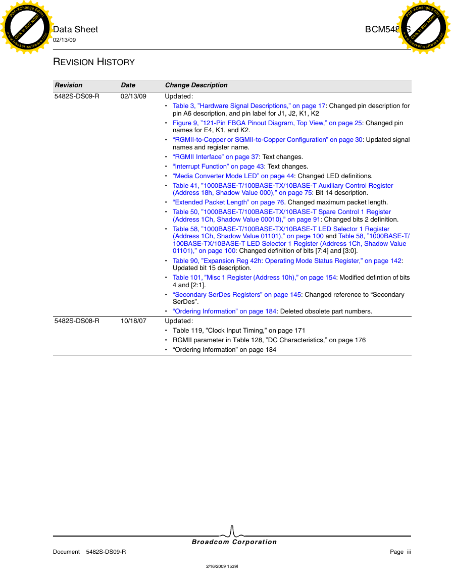
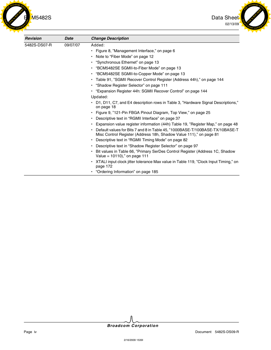
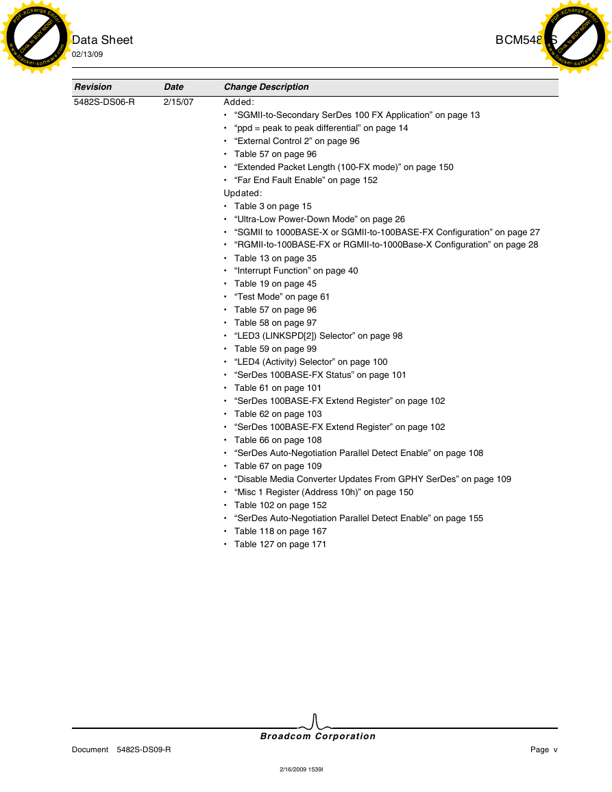
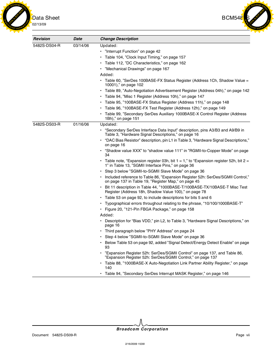
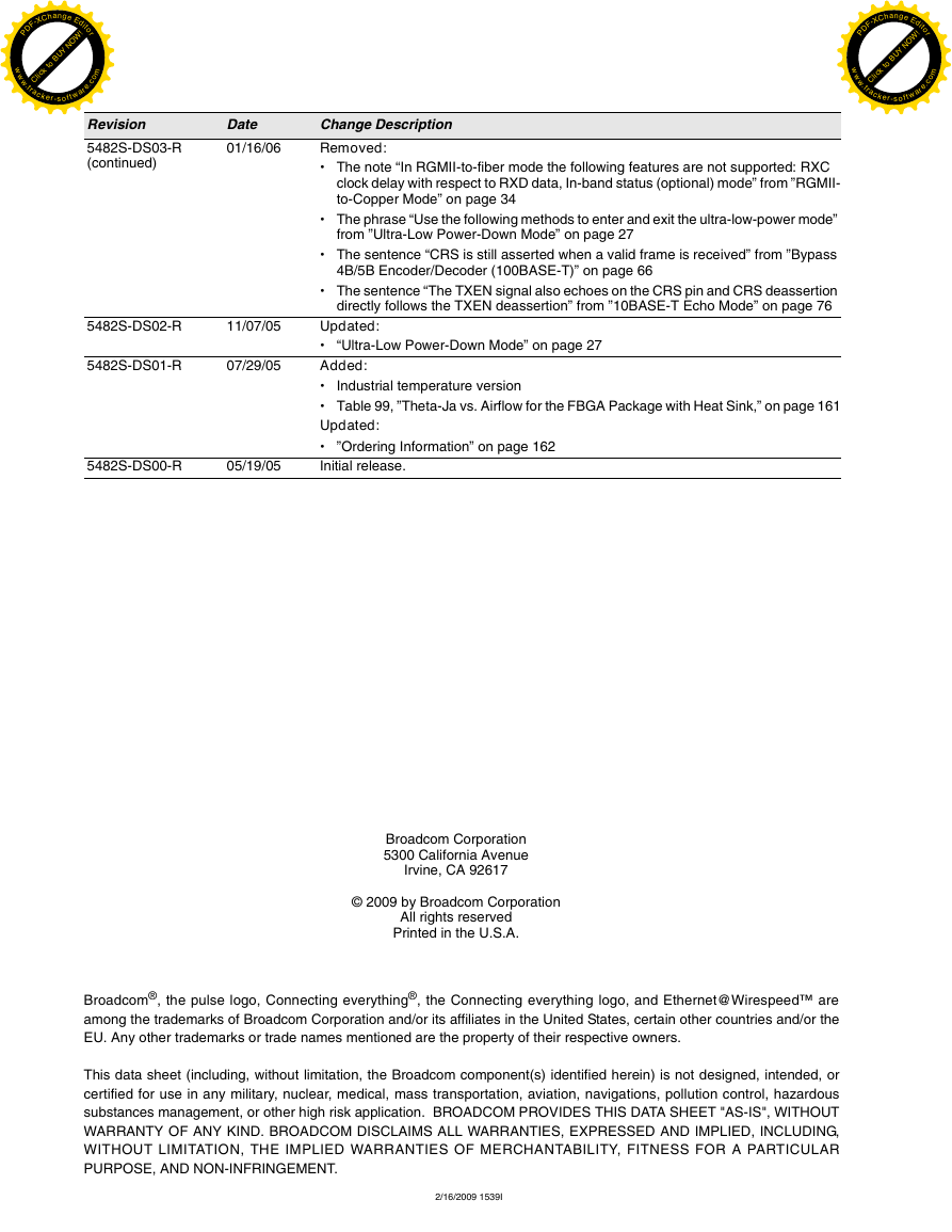
Revision History
Table of Contents
List of Figures
List of Tables
Section 1: Functional Description
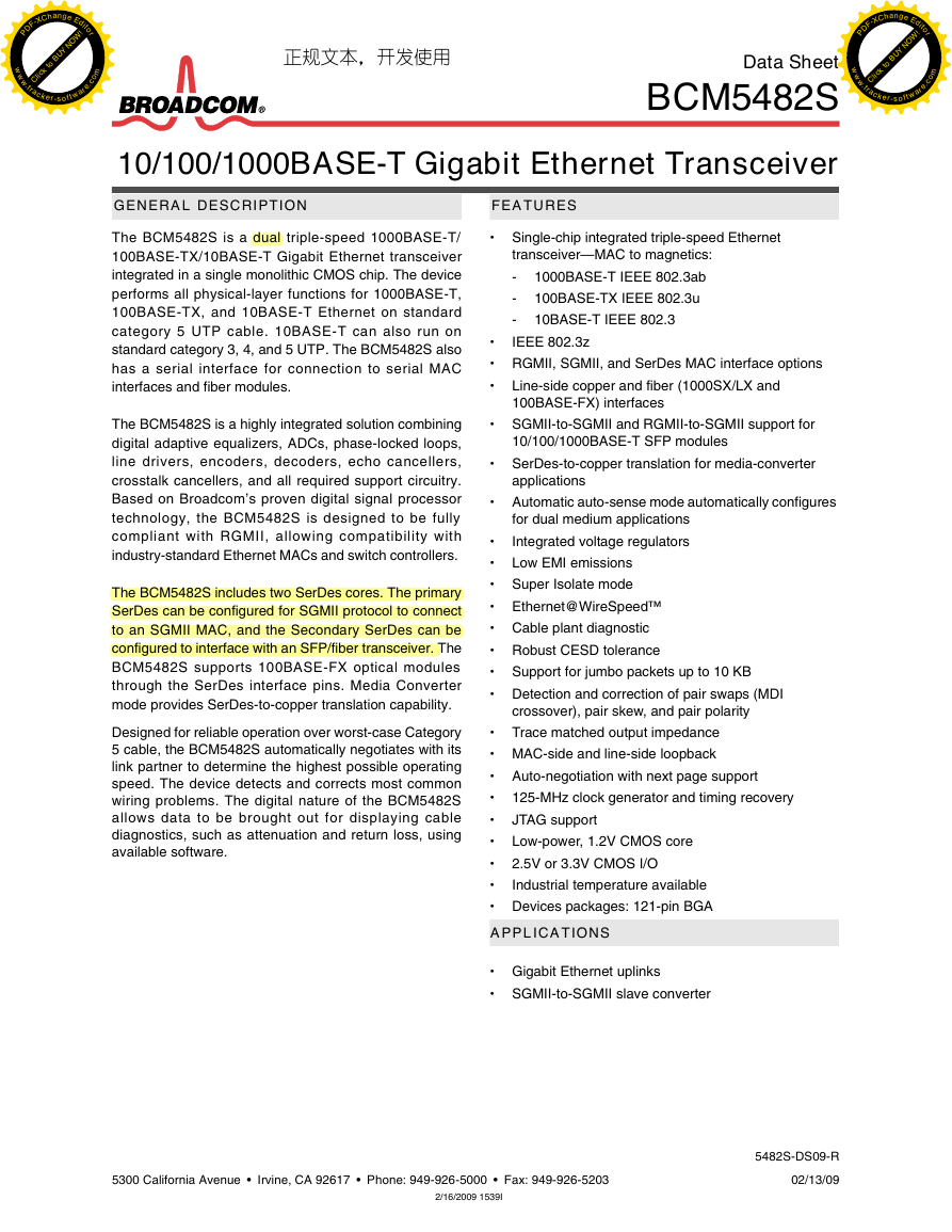
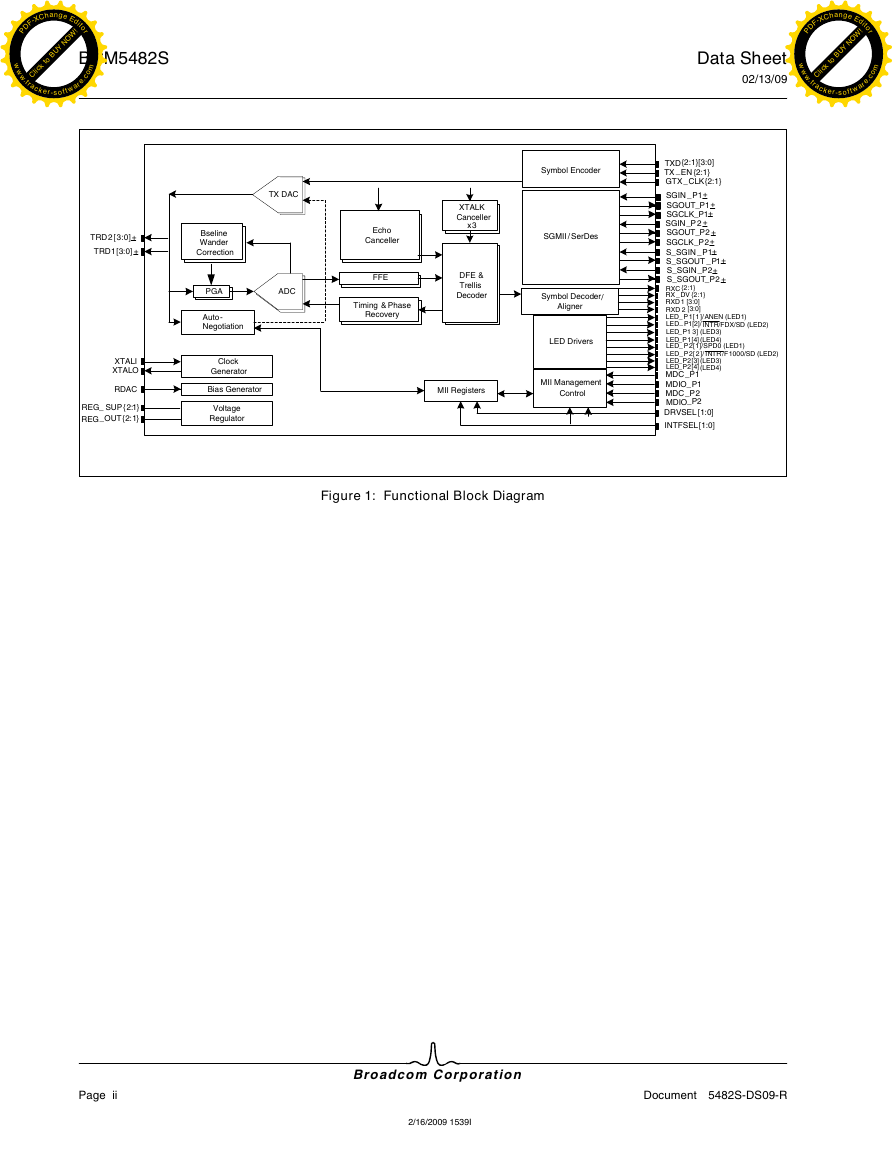
Overview
Modes of Operation
Copper Mode
Fiber Mode
SGMII Mode
Media Converter Mode
Reduced Gigabit Media Independent Interface
Serial GMII Interface
SerDes Interface (Complies with IEEE 802.3™, Clauses 36 and 37)
Management Interface
Encoder
Decoder
Carrier Sense
Link Monitor
Digital Adaptive Equalizer
Echo Canceler
Crosstalk Canceler
Analog-to-Digital Converter
Clock Recovery/Generator
Baseline Wander Correction
Multimode TX Digital-to-Analog Converter
Stream Cipher
Wire Map and Pair Skew Correction
Automatic MDI Crossover
10/100BASE-T Forced Mode Auto-MDIX
Auto-negotiation
Copper Mode
Fiber Mode
SGMII Mode
Media Converter Mode
Synchronous Ethernet
BCM5482SSGMII-to-Fiber Mode
BCM5482SSGMII-to-Copper Mode
Energy Detect
Internal Voltage Regulators
Power-Down Modes
Jumbo Packets
Copper Modes
Fiber Mode
SGMII/Media Converter Mode
SGMII-to-Secondary SerDes 100 FX Application
Section 2: Hardware Signal Descriptions
Section 3: Pinout Diagram
Section 4: Operational Description
Reset
PHY Address
Isolate Mode
Copper Mode
Fiber Mode
Standby Power-Down Mode
Auto Power-Down Mode
CLK125 Clock Output
Ultra-Low Power-Down Mode
Reset Requirements
Energy Detect Function
Internal Loopback Mode
RGMII to Copper Configuration
SGMII to Copper Configuration
RGMII to 1000BASE-X Configuration
SGMII to 1000BASE-X or SGMII-to-100BASE-FX Configuration
Lineside (Remote) Loopback Mode
RGMII-to-Copper or SGMII-to-Copper Configuration
SGMII-to-1000BASE-X Configuration
RGMII-to-100BASE-FX or RGMII-to-1000Base-X Configuration
SGMII-to-100BASE-FX Configuration
SGMII/Media Converter Mode
External Loopback Mode
Full-Duplex Operation
Copper Mode
Fiber Mode
Ethernet@Wirespeed™
Software Enable
Changing the Number of Failed Link Attempts Before Ethernet@Wirespeed Downgrade
Monitoring Ethernet@Wirespeed
Master/Slave Configuration
Next Page Exchange
100BASE-FX
RGMII Interface
RGMII-to-SGMII Slave Mode
SGMII Interface
Control Information Exchange Between Links
SGMII-to-SGMII Slave Mode
SerDes Interface
Media Converter Mode
Copper/Fiber Mode Auto-Detection
SGMII/Media Converter Mode Auto-Detection
Voltage Regulators
Dual-Input Configuration/LED Output Function
General-Purpose LED Programmability
Interrupt Function
LED Modes
Multicolor LED
Open/Short LED
Energy Link LED
Media Converter Mode LED
Additional LED Modes
Section 5: Register Summary
MII Management Interface Register Programming
Register Map
Register Notations
1000BASE-T/100BASE-TX/10BASE-T Registers Descriptions
1000BASE-T/100BASE-TX/10BASE-T MII Control
Reset
Internal Loopback
Speed Selection (LSB)
Auto-negotiation Enable
Power-Down
Isolate
Restart Auto-negotiation
Duplex Mode
Speed Selection (MSB)
Collision Test
1000BASE-T/100BASE-TX/10BASE-T MII Status
100BASE-T4 Capable
100BASE-X Full-Duplex Capable
100BASE-X Half-Duplex Capable
10BASE-T Full-Duplex Capable
10BASE-T Half-Duplex Capable
100BASE-T2 Full-Duplex Capable
100BASE-T2 Half-Duplex Capable
Extended Status
Management Frames Preamble Suppression
Auto-negotiation Complete
Remote Fault
Auto-negotiation Ability
Link Status
Jabber Detect
Extended Capability
1000BASE-T/100BASE-TX/10BASE-T PHY Identifier
1000BASE-T/100BASE-TX/10BASE-T Auto-negotiation Advertisement
Next Page
Remote Fault
Reserved Technology
Asymmetric Pause
Pause Capable
100BASE-T4 Capable
100BASE-TX Full-Duplex Capable
100BASE-TX Half-Duplex Capable
10BASE-T Full-Duplex Capable
10BASE-T Half-Duplex Capable
Selector Field
1000BASE-T/100BASE-TX/10BASE-T Auto-negotiation Link Partner Ability
Next Page
Acknowledge
Remote Fault
Reserved Technology
Asymmetric Pause
Pause Capable
100BASE-T4 Capable
100BASE-TX Full-Duplex Capable
100BASE-TX Half-Duplex Capable
10BASE-T Full-Duplex Capable
10BASE-T Half-Duplex Capable
Protocol Selector Field
1000BASE-T/100BASE-TX/10BASE-T Auto-negotiation Expansion
Parallel Detection Fault
Link Partner Next Page Ability
Next Page Capable
Page Received
Link Partner Auto-negotiation Ability
1000BASE-T/100BASE-TX/10BASE-T Next Page Transmit
Next Page
Message Page
Acknowledge2
Toggle
Message/Unformatted Code Field
1000BASE-T/100BASE-TX/10BASE-T Link Partner Received Next Page
Next Page
Acknowledge
Message Page
Acknowledge2
Toggle
Message Code Field
1000BASE-T Control
Test Mode
Master/Slave Configuration Enable
Master/Slave Configuration Value
Repeater/DTE
Advertise 1000BASE-T Full-Duplex Capability
Advertise 1000BASE-T Half-Duplex Capability
1000BASE-T Status
Master/Slave Configuration Fault
Master/Slave Configuration Resolution
Local Receiver Status
Remote Receiver Status
1000BASE-T Full-Duplex Capability
1000BASE-T Half-Duplex Capability
Idle Error Count
1000BASE-T/100BASE-TX/10BASE-T IEEE Extended Status
1000BASE-X Full-Duplex Capable
1000BASE-X Half-Duplex Capable
1000BASE-T Full-Duplex Capable
1000BASE-T Half-Duplex Capable
1000BASE-T/100BASE-TX/10BASE-T PHY Extended Control
Disable Automatic MDI Crossover
Transmit Disable
Interrupt Disable
Force Interrupt
Bypass 4B/5B Encoder/Decoder (100BASE-T)
Bypass Scrambler/Descrambler (100BASE-T)
Bypass MLT3 Encoder/Decoder (100BASE-T)
Bypass Receive Symbol Alignment (100BASE-T)
Reset Scrambler (100BASE-T)
Enable LED Traffic Mode
Force LEDs On
Force LEDs Off
1000-Mbps PCS Transmit FIFO Elasticity (Jumbo Packets)
1000BASE-T/100BASE-TX/10BASE-T PHY Extended Status
Auto-negotiation Base Page Selector Field Mismatch
Ethernet@WireSpeed Downgrade
MDI Crossover State
Interrupt Status
Remote Receiver Status
Local Receiver Status
Locked
Link Status
CRC Error Detected
Carrier Extension Error Detected
Bad SSD Detected (False Carrier)
Bad ESD Detected (Premature End)
Receive Error Detected
Transmit Error Detected
Lock Error Detected
MLT3 Code Error Detected
1000BASE-T/100BASE-TX/10BASE-T Receive Error Counter
Receive Error Counter
1000BASE-T/100BASE-TX/10BASE-T False Carrier Sense Counter
False Carrier Sense Counter
1000BASE-T/100BASE-TX/10BASE-T Receiver NOT_OK Counter
Local Receiver NOT_OK Counter
Remote Receiver NOT_OK Counter
1000BASE-T/100BASE-TX/10BASE-T Expansion Register Access
Expansion Register Select
Expansion Register Accessed
1000BASE-T/100BASE-TX/10BASE-T Auxiliary Control Shadow Value Access Register
External Loopback
Extended Packet Length
Edge-Rate Control (1000BASE-T)
Transmit Mode
Disable Partial Response Filter
Edge-Rate Control (100BASE-TX)
Shadow Register Select
10BASE-T
Manchester Code Error
EOF Error
Polarity Error
Block RX_DV Extension (IPG)
10BASE-T TXC Invert Mode
Jabber Disable
1000BASE-T Signal Detect Threshold
10BASE-T Signal Detect Threshold
10BASE-T Echo Mode
SQE Enable Mode
10BASE-T No Dribble
Shadow Register Select
1000BASE-T/100BASE-TX/10BASE-T Power/MII Control
Low-Power Driver
Super Isolate (Copper Only)
Shadow Register Select
1000BASE-T/100BASE-TX/10BASE-T Misc Test Register
Lineside [Remote] Loopback Enable
Lineside [Remote] Loopback Tristate
Swap RX MDIX
10BASE-T Halfout
Shadow Register Select
1000BASE-T/100BASE-TX/10BASE-T Misc Control
Write Enable (Bits 11:3)
Shadow Register Read Selector
Packet Counter Mode
Force Auto-MDIX Mode
RGMII Timing Mode
RGMII RX_DV Mode
RGMII Out-of-Band Status (OOBS) Disable
Ethernet@WireSpeed Enable
MDIO All PHY Select
Shadow Register Select
1000BASE-T/100BASE-TX/10BASE-T Auxiliary Status Summary
Auto-negotiation Complete
Auto-negotiation Complete Acknowledge
Auto-negotiation Acknowledge Detect
Auto-negotiation Ability Detect
Auto-negotiation Next Page Wait
Auto-negotiation HCD (Current Operating Speed and Duplex Mode)
Parallel Detection Fault
Remote Fault
Auto-negotiation Page Received
Link Partner Auto-negotiation Ability
Link Partner Next Page Ability
Link Status
Pause Resolution—Receive Direction and Transmit Direction
1000BASE-T/100BASE-TX/10BASE-T Interrupt Status
Signal Detect/Energy Detect Change
Illegal Pair Swap
MDIX Status Change
Exceeded High Counter Threshold
Exceeded Low Counter Threshold
Auto-negotiation Page Received
No HCD Link
No HCD
Negotiated Unsupported HCD
Scrambler Synchronization Error
Remote Receiver Status Change
Local Receiver Status Change
Duplex Mode Change
Link Speed Change
Link Status Change
CRC Error
1000BASE-T/100BASE-TX/10BASE-T Interrupt Mask
Interrupt Mask Vector
1000BASE-T/100BASE-TX/10BASE-T Register 1Ch Access
1000BASE-T/100BASE-TX/10BASE-T Spare Control 1
Write Enable
Shadow Register Selector
Link LED Mode
1000BASE-T/100BASE-TX/10BASE-T Clock Alignment Control
Write Enable
Shadow Register Selector
GTXCLK Clock Delay Enable
1000BASE-T/100BASE-TX/10BASE-T Spare Control 2
Write Enable
Shadow Register Selector
Ethernet@WireSpeed Retry Limit
Energy Detect on INTR Pin
1000BASE-T/100BASE-TX/10BASE-T Spare Control 3
Write Enable
Shadow Register Selector
TXC/RXC Disable During Auto Power-Down
TXC Disable
Signal Detect/Energy Detect Enable
CLK125 Auto Power-Down
CLK125 Output
1000BASE-T/100BASE-TX/10BASE-T LED Status
Write Enable
Shadow Register Selector
Slave Indicator
FDX Indicator
INTR Indicator
LINKSPD Indicator
Transmit Indicator
Receive Indicator
Quality Indicator
1000BASE-T/100BASE-TX/10BASE-T LED Control
Write Enable
Shadow Register Selector
Override Media Converter LED Mode
Activity/Link LED Enable
ACTIVITY LED Enable
Remote Fault LED Enable
Link Utilization LED Selector
1000BASE-T/100BASE-TX/10BASE-T Auto Power-Down
Write Enable
Shadow Register Selector
TXC/RXC Disable During Auto Power-Down
Auto Power-Down Mode
Sleep Timer Select
Wake-up Timer Select
1000BASE-T/100BASE-TX/10BASE-T LED Selector 1
External Control 2
Write Enable
Shadow Register Selector
LED3 (LINKSPD[2]) Selector
LED1 (LINKSPD[1]) Selector
1000BASE-T/100BASE-TX/10BASE-T LED Selector 2
Write Enable
Shadow Register Selector
LED2 (INTR) Selector
LED4 (Activity) Selector
1000BASE-T/100BASE-TX/10BASE-T LED GPIO Control/Status
Write Enable
Shadow Register Selector
LED I/O Status
Programmable LED I/O Control
SerDes 100BASE-FX Status
Write Enable
Shadow Register Selector
Bad ESD Detected (Premature End)
False Carrier Detected
Transmit Error Detected
Receive Error Detected
Lock Timer Expired
Lost Lock
Faulting
Locked
100FX Link (SerDes)
SerDes 100BASE-FX Extend Register
Write Enable
Shadow Register Selector
Far End Fault Enable
100BASE-FX SerDes Full-Duplex
100BASE-FX SerDes Enable
Secondary SerDes Control
Write Enable
Shadow Register Selector
Secondary SerDes Link Status Change
Secondary SerDes Link
Secondary SerDes Duplex
Secondary SerDes 100BASE-FX Full-Duplex
Secondary SerDes 100BASE-FX Mode
Secondary SerDes LED Mode
Select Sync Status
Select SD
Secondary SerDes Select
SGMII Slave
Write Enable
Shadow Register Selector
SerDes Link
SerDes Duplex
SerDes Speed
SerDes Link Status Change
Mode Select
RGMII-to-SGMII Slave 10/100 TX FIFO Frequency Lock Mode
SGMII Slave Mode
SGMII Slave Auto-Detection
Primary SerDes Control
Write Enable
Shadow Register Selector
Signal Detect Enable
SerDes Auto-Negotiation Parallel Detect Enable
Misc 1000BASE-X Control 2
SerDes Transmit Disable
Signal Detect Enable
Disable Media Converter Updates From GPHY SerDes
Force XMIT = Data
1000BASE-X Auto-Detect SGMII/Media Converter
Write Enable
Shadow Register Selector
SerDes Resolution Fault
1000BASE-T PCS Transmit FIFO Elasticity (SGMII/Media Converter Mode)
SGMII 10/100BASE-T RX FIFO Frequency Lock Mode
SGMII/Media Converter Auto-Detect Mode Enable
1000BASE-X Auto-negotiation Debug
Write Enable
Shadow Register Selector
Consistency Mismatch
RUDI Invalid
Sync Status Detected
AN_Sync_Status
Idle Detect State
Complete Acknowledge State
Acknowledge Detect State
Ability Detect State
Sync Status Failed
AN_Enable State
Auxiliary 1000BASE-X Control
Write Enable
Shadow Register Selector
Use SerDes Mode Counters
Disable Remote Fault Sensing
Auto-negotiation Error Timer Enable
Comma Detect Enable
1000BASE-X PCS Transmit, SGMII 10/100BASE-T Transmit and Receive FIFO Elasticity
Disable CRC Checker
Auxiliary 1000BASE-X Status
Write Enable
Shadow Register Selector
Link Status Change
SGMII Selector Mismatch
Auto-negotiation Resolution Error
Link Partner Remote Fault
Auto-negotiation Page Received
Current Operating Duplex Mode
Link Status
PAUSE Resolution—Receive Side
PAUSE Resolution—Transmit Side
Misc 1000BASE-X Status
Write Enable
Shadow Register Selector
False Carrier Detected
CRC Error Detected
Transmit Error Detected
Receive Error Detected
Carrier Extend Error Detected
Early End Extension Detected
Copper/Fiber Auto-Detect Medium
Write Enable
Shadow Register Selector
Secondary SerDes Auto-Detection
Invert Fiber Signal Detect from SD Pin
Fiber In-Use LED Mode
Fiber LED Mode
Qualify Fiber Signal Detect with Sync Status
Auto-Detect Media Default
Auto-detect Media Priority
Auto-detect Media Enable
Mode Control
Write Enable
Shadow Register Selector
Mode Select Change
Copper Link
SerDes Link
Copper Energy Detect
Fiber Signal Detect
Mode Select
Enable 1000BASE-X Registers
1000BASE-T/100BASE-TX/10BASE-T Master/Slave Seed
Enable Shadow Register
Master/Slave Seed Match
Link Partner Repeater/DTE Bit
Link Partner Manual Master/Slave Configuration Value
Link Partner Manual Master/Slave Configuration Enable
Local Master/Slave Seed Value
1000BASE-T/100BASE-TX/10BASE-T HCD Status
Enable Shadow Register
Ethernet@WireSpeed Disable Gigabit Advertising
Ethernet@WireSpeed Disable 100BASE-TX Advertising
Ethernet@WireSpeed Downgrade
HCD 1000BASE-T FDX
HCD 1000BASE-T
HCD 100BASE-TX FDX
HCD 100BASE-T
HCD 10BASE-T FDX
HCD 10BASE-T
HCD 1000BASE-T FDX (Link Never Came Up)
HCD 1000BASE-T (Link Never Came Up)
HCD 100BASE-TX FDX (Link Never Came Up)
HCD 100BASE-TX (Link Never Came Up)
HCD 10BASE-T FDX (Link Never Came Up)
HCD 10BASE-T FDX (Link Never Came Up)
1000BASE-T/100BASE-TX/10BASE-T Test Register 1
CRC Error Counter Selector
Manual Swap MDI State
Primary SerDes Register Descriptions
1000BASE-X MII Control
Reset
Internal Loopback
Auto-negotiation Enable
Power-Down
Isolate
Restart Auto-negotiation
Duplex Mode
Collision Test
1000BASE-X MII Status
100BASE-T4 Capable
100BASE-X Full-Duplex Capable
100BASE-X Half-Duplex Capable
10BASE-T Full-Duplex Capable
10BASE-T Half-Duplex Capable
100BASE-T2 Full-Duplex Capable
100BASE-T2 Half-Duplex Capable
Extended Status
Management Frames Preamble Suppression
Auto-negotiation Complete
Remote Fault
Auto-negotiation Ability
Link Status
Jabber Detect
Extended Capability
1000BASE-X Auto-negotiation Advertisement
Remote Fault
Pause
Half-Duplex Capable
Full-Duplex Capable
1000BASE-X Auto-Negotiation Link Partner Ability
1000BASE-X Mode
Next Page
Acknowledge
Remote Fault
Pause
Half-Duplex Capable
Full-Duplex Capable
SGMII Mode
Copper Link
Acknowledge
Copper Duplex
Copper Speed
1000BASE-X Auto-negotiation Extended Status
Next Page Capable
Page Received
1000BASE-X IEEE Extended Status
1000BASE-X Full-Duplex Capable
1000BASE-X Half-Duplex Capable
1000BASE-T Full-Duplex Capable
1000BASE-T Half-Duplex Capable
Expansion Registers
Expansion Register 00h: Receive/Transmit Packet Counter
Packet Counter (Copper Only)
Expansion Register 01h: Expansion Interrupt Status
Mode Select Change
SerDes Link Status Change
RUDI_C Detected
Expansion Interrupt Status
Transmit CRC Error (Copper Only)
Expansion Register 02h: Expansion Interrupt Mask
Expansion Register 04h: Multicolor LED Selector
Flash Now
In Phase
MULTICOLOR[2] LED Selector
MULTICOLOR[1] LED Selector
Expansion Register 05h: Multicolor LED Flash Rate Controls
Alternating Rate
Flash Rate
Expansion Register 06h: Multicolor LED Programmable Blink Controls
Blink Update Now
Blink Rate
Expansion Register 42h: Operating Mode Status
SerDes Link
SerDes Speed
SerDes Duplex
Copper Link
Copper Speed
Copper Duplex
Copper Energy Detect
Fiber Signal Detect
Sync Status
Operating Mode Status
Expansion Register 44h: SGMII Recover Control
Select Recovered CLK
Expansion Register 50h: SerDes/SGMII RX Control
RX Power Down
Expansion Register 52h: SerDes/SGMII Control
TX Clock Pad Disable R/W
Secondary SerDes Registers
1000BASE-X Control
Secondary SerDes Reset
Loopback
Manual Speed [0]
Auto-negotiation Enable
Power-Down
Restart Auto-negotiation
Manual Full-Duplex Mode
Manual Speed [1]
1000BASE-X Auto-Negotiation Advertisement
Next Page
Remote Fault
Pause
Half Duplex
Full Duplex
1000BASE-X Auto-Negotiation Link Partner Ability
Next Page
Acknowledge
Remote Fault
Pause
Half-Duplex Capable
Full-Duplex Capable
Copper Link
Acknowledge
Copper Duplex
Copper Speed
SGMII Selector
1000BASE-X Auto-Negotiation Secondary SerDes Register
Next Page Receive Location Able
Next Page Receive Location
Page Received
1000BASE-X Auto-Negotiation Next Page Transmit
Next Page
Message Page
Acknowledge2
Toggle
Code Field
1000BASE-X Auto-Negotiation Link Partner Next Page
Next Page
1000BASE-X Extended Status
1000BASE-X Full-Duplex Capable
1000BASE-X Half-Duplex Capable
1000BASE-T Full-Duplex Capable
1000BASE-T Half-Duplex Capable
Misc 1
Enable Interrupts
Invert Signal Detect
Extended Packet Length (100-FX Mode)
100BASE-FX Status
100FX Link Status Change (SerDes)
Bad ESD Detected (Premature End)
False Carrier Detected
Transmit Error Detected
Receive Error Detected
Lock Timer Expired
Lost Lock
Faulting
Locked
100FX Link (SerDes)
100BASE-FX Test
Far End Fault Enable
Unidirectional
Packet Counter
Packet Counter
Error Counter
Error Counter
SGMII Slave
SerDes Link
SerDes Duplex
SerDes Speed
SerDes Link Status Change
SGMII Slave Mode
SGMII Slave Auto-Detection
Secondary SerDes Control
SerDes Detect Enable
SerDes Auto-Negotiation Parallel Detect Enable
Misc 1000BASE-X Control 2
SerDes Transmit Disable
Signal Detect Enable
Disable GBIC Updates from GPHY SerDes
Force XMIT = Data
Misc 1000-X Control 3
XMIT = Data
Fiber SD
SD Amplitude Status
SD Amplitude Status Changed
Enable CRC Fragment Errors
Auto-Negotiation 1000BASE-X Debug
Consistency Mismatch
RUDI Invalid
Sync Status Detected
AN_Sync_Status
Idle Detect State
Complete Acknowledge State
Acknowledge Detect State
Ability Detect State
Error State
Sync Status Failed
AN_Enable State
Secondary SerDes Auxiliary 1000BASE-X Control Register
Disable Remote Fault Sensing
Auto-negotiation Error Timer Enable
Comma Detect Enable
1000BASE-X PCS Transmit, SGMII 10/100BASE-T Transmit, and Receive FIFO Elasticity
Disable CRC Checker
Auxiliary 1000BASE-X Status
Secondary SerDes Link Status Change
SGMII Selector Mismatch
Auto-negotiation Resolution Error
Link Partner Remote Fault
Auto-negotiation Page Received
Current Operating Duplex Mode
SerDes Link
PAUSE Resolution—Receive Side
PAUSE Resolution—Transmit Side
Misc 1000BASE-X Status
Transmit FIFO Error
Receive FIFO Error
Bad FIFO Pointer
False Carrier Detected
CRC Error Detected
Transmit Error Detected
Receive Error Detected
Carrier Extend Error Detected
Early End Extension Detected
Spare Register
Invert Interrupt
Secondary SerDes Interrupt Status
SerDes CRC Error
SGMII Slave Mode Change
100BASE-FX SerDes Mode Change
SerDes Auto-negotiation Page Received
Secondary SerDes Select Change
Signal Detect Amplitude Change
SerDes Link Status Change
Lost Sync Status
Rudi-C Detected
SerDes Auto-negotiation Error
Idle Codeword Detected
Secondary SerDes Interrupt MASK
Secondary SerDes Interrupt Mask
Secondary SerDes Lineside Loopback Control
Secondary SerDes Lineside Loopback
Section 6: Timing and AC Characteristics
Section 7: Electrical Characteristics
Section 8: Mechanical and Thermal Data
RoHS-Compliant Packaging
Mechanical Drawings
Thermal Information
Junction Temperature Estimation and YJT vs. qJC
Section 9: Ordering Information



 2023年江西萍乡中考道德与法治真题及答案.doc
 2012年重庆南川中考生物真题及答案.doc
 2013年江西师范大学地理学综合及文艺理论基础考研真题.doc
 2020年四川甘孜小升初语文真题及答案I卷.doc
 2020年注册岩土工程师专业基础考试真题及答案.doc
 2023-2024学年福建省厦门市九年级上学期数学月考试题及答案.doc
 2021-2022学年辽宁省沈阳市大东区九年级上学期语文期末试题及答案.doc
 2022-2023学年北京东城区初三第一学期物理期末试卷及答案.doc
 2018上半年江西教师资格初中地理学科知识与教学能力真题及答案.doc
 2012年河北国家公务员申论考试真题及答案-省级.doc
 2020-2021学年江苏省扬州市江都区邵樊片九年级上学期数学第一次质量检测试题及答案.doc
 2022下半年黑龙江教师资格证中学综合素质真题及答案.doc