logo资料库

imx6q数据手册.pdf

第1页 / 共168页
第2页 / 共168页
第3页 / 共168页
第4页 / 共168页
第5页 / 共168页
第6页 / 共168页
第7页 / 共168页
第8页 / 共168页
资料共168页,剩余部分请下载后查看
i.MX 6Dual/6Quad Applications Processors for Consumer Products Data Sheet
1 Introduction
1.1 Ordering Information
1.2 Features
1.3 Updated Signal Naming Convention
2 Architectural Overview
2.1 Block Diagram
3 Modules List
3.1 Special Signal Considerations
3.2 Recommended Connections for Unused Analog Interfaces
4 Electrical Characteristics
4.1 Chip-Level Conditions
4.1.1 Absolute Maximum Ratings
4.1.2 Thermal Resistance
4.1.2.1 FCPBGA Package Thermal Resistance
4.1.3 Operating Ranges
4.1.4 External Clock Sources
4.1.5 Maximum Supply Currents
4.1.6 Low Power Mode Supply Currents
4.1.7 USB PHY Current Consumption
4.1.7.1 Power Down Mode
4.1.8 SATA Typical Power Consumption
4.1.9 PCIe 2.0 Maximum Power Consumption
4.1.10 HDMI Maximum Power Consumption
4.2 Power Supplies Requirements and Restrictions
4.2.1 Power-Up Sequence
4.2.2 Power-Down Sequence
4.2.3 Power Supplies Usage
4.3 Integrated LDO Voltage Regulator Parameters
4.3.1 Digital Regulators (LDO_ARM, LDO_PU, LDO_SOC)
4.3.2 Regulators for Analog Modules
4.3.2.1 LDO_1P1
4.3.2.2 LDO_2P5
4.3.2.3 LDO_USB
4.4 PLL Electrical Characteristics
4.4.1 Audio/Video PLL Electrical Parameters
4.4.2 528 MHz PLL
4.4.3 Ethernet PLL
4.4.4 480 MHz PLL
4.4.5 MLB PLL
4.4.6 ARM PLL
4.5 On-Chip Oscillators
4.5.1 OSC24M
4.5.2 OSC32K
4.6 I/O DC Parameters
4.6.1 XTALI and RTC_XTALI (Clock Inputs) DC Parameters
4.6.2 General Purpose I/O (GPIO) DC Parameters
4.6.3 DDR I/O DC Parameters
4.6.3.1 LPDDR2 Mode I/O DC Parameters
4.6.3.2 DDR3/DDR3L Mode I/O DC Parameters
4.6.4 LVDS I/O DC Parameters
4.6.5 MLB 6-Pin I/O DC Parameters
4.7 I/O AC Parameters
4.7.1 General Purpose I/O AC Parameters
4.7.2 DDR I/O AC Parameters
4.7.3 LVDS I/O AC Parameters
4.7.4 MLB 6-Pin I/O AC Parameters
4.8 Output Buffer Impedance Parameters
4.8.1 GPIO Output Buffer Impedance
4.8.2 DDR I/O Output Buffer Impedance
4.8.3 LVDS I/O Output Buffer Impedance
4.8.4 MLB 6-Pin I/O Differential Output Impedance
4.9 System Modules Timing
4.9.1 Reset Timing Parameters
4.9.2 WDOG Reset Timing Parameters
4.9.3 External Interface Module (EIM)
4.9.3.1 EIM Interface Pads Allocation
4.9.3.2 General EIM Timing-Synchronous Mode
4.9.3.3 Examples of EIM Synchronous Accesses
4.9.3.4 General EIM Timing-Asynchronous Mode
4.9.4 DDR SDRAM Specific Parameters (DDR3/DDR3L and LPDDR2)
4.9.4.1 DDR3/DDR3L Parameters
4.9.4.2 LPDDR2 Parameters
4.10 General-Purpose Media Interface (GPMI) Timing
4.10.1 Asynchronous Mode AC Timing (ONFI 1.0 Compatible)
4.10.2 Source Synchronous Mode AC Timing (ONFI 2.x Compatible)
4.10.3 Samsung Toggle Mode AC Timing
4.10.3.1 Command and Address Timing
4.10.3.2 Read and Write Timing
4.11 External Peripheral Interface Parameters
4.11.1 AUDMUX Timing Parameters
4.11.2 ECSPI Timing Parameters
4.11.2.1 ECSPI Master Mode Timing
4.11.2.2 ECSPI Slave Mode Timing
4.11.3 Enhanced Serial Audio Interface (ESAI) Timing Parameters
4.11.4 Ultra High Speed SD/SDIO/MMC Host Interface (uSDHC) AC Timing
4.11.4.1 SD/eMMC4.3 (Single Data Rate) AC Timing
4.11.4.2 eMMC4.4/4.41 (Dual Data Rate) eSDHCv3 AC Timing
4.11.4.3 SDR50/SDR104 AC Timing
4.11.4.4 Bus Operation Condition for 3.3 V and 1.8 V Signaling
4.11.5 Ethernet Controller (ENET) AC Electrical Specifications
4.11.5.1 ENET MII Mode Timing
4.11.5.2 RMII Mode Timing
4.11.5.3 RGMII Signal Switching Specifications
4.11.6 Flexible Controller Area Network (FlexCAN) AC Electrical Specifications
4.11.7 HDMI Module Timing Parameters
4.11.7.1 Latencies and Timing Information
4.11.7.2 Electrical Characteristics
4.11.8 Switching Characteristics
4.11.9 I2C Module Timing Parameters
4.11.10 Image Processing Unit (IPU) Module Parameters
4.11.10.1 IPU Sensor Interface Signal Mapping
4.11.10.2 Sensor Interface Timings
4.11.10.3 Electrical Characteristics
4.11.10.4 IPU Display Interface Signal Mapping
4.11.10.5 IPU Display Interface Timing
4.11.10.6 Synchronous Interfaces to Standard Active Matrix TFT LCD Panels
4.11.11 LVDS Display Bridge (LDB) Module Parameters
4.11.12 MIPI D-PHY Timing Parameters
4.11.12.1 Electrical and Timing Information
4.11.12.2 D-PHY Signaling Levels
4.11.12.3 HS Line Driver Characteristics
4.11.12.4 Possible DVCMTX and DVOD Distortions of the Single-ended HS Signals
4.11.12.5 D-PHY Switching Characteristics
4.11.12.6 High-Speed Clock Timing
4.11.12.7 Forward High-Speed Data Transmission Timing
4.11.12.8 Reverse High-Speed Data Transmission Timing
4.11.12.9 Low-Power Receiver Timing
4.11.13 HSI Host Controller Timing Parameters
4.11.13.1 Synchronous Data Flow
4.11.13.2 Pipelined Data Flow
4.11.13.3 Receiver Real-Time Data Flow
4.11.13.4 Synchronized Data Flow Transmission with Wake
4.11.13.5 Stream Transmission Mode Frame Transfer
4.11.13.6 Frame Transmission Mode (Synchronized Data Flow)
4.11.13.7 Frame Transmission Mode (Pipelined Data Flow)
4.11.13.8 DATA and FLAG Signal Timing Requirement for a 15 pF Load
4.11.13.9 DATA and FLAG Signal Timing
4.11.14 MediaLB (MLB) Characteristics
4.11.14.1 MediaLB (MLB) DC Characteristics
4.11.14.2 MediaLB (MLB) Controller AC Timing Electrical Specifications
4.11.15 PCIe PHY Parameters
4.11.15.1 PCIE_REXT Reference Resistor Connection
4.11.16 Pulse Width Modulator (PWM) Timing Parameters
4.11.17 SATA PHY Parameters
4.11.17.1 Transmitter and Receiver Characteristics
4.11.17.2 SATA_REXT Reference Resistor Connection
4.11.18 SCAN JTAG Controller (SJC) Timing Parameters
4.11.19 SPDIF Timing Parameters
4.11.20 SSI Timing Parameters
4.11.20.1 SSI Transmitter Timing with Internal Clock
4.11.20.2 SSI Receiver Timing with Internal Clock
4.11.20.3 SSI Transmitter Timing with External Clock
4.11.20.4 SSI Receiver Timing with External Clock
4.11.21 UART I/O Configuration and Timing Parameters
4.11.21.1 UART RS-232 I/O Configuration in Different Modes
4.11.21.2 UART RS-232 Serial Mode Timing
4.11.22 USB HSIC Timings
4.11.22.1 Transmit Timing
4.11.22.2 Receive Timing
4.11.23 USB PHY Parameters
5 Boot Mode Configuration
5.1 Boot Mode Configuration Pins
5.2 Boot Devices Interfaces Allocation
6 Package Information and Contact Assignments
6.1 Updated Signal Naming Convention
6.2 21 x 21 mm Package Information
6.2.1 Case FCPBGA, 21 x 21 mm, 0.8 mm Pitch, 25 x 25 Ball Matrix
6.2.1.1 21 x 21 mm Bare Die Package
6.2.2 21 x 21 mm Ground, Power, Sense, and Reference Contact Assignments
6.2.3 21 x 21 mm, 0.8 mm Pitch Ball Map
7 Revision History
Contact Information
Freescale Semiconductor Data Sheet: Technical Data Document Number: IMX6DQCEC Rev. 3, 02/2014 MCIMX6QxExxxxC MCIMX6QxExxxxD MCIMX6DxExxxxC MCIMX6DxExxxxD Package Information Case FCPBGA 21 x 21 mm, 0.8 mm pitch Ordering Information See Table 1 on page 3 1 Introduction . . . . . . . . . . . . . . . . . . . . . . . . . . . . . . . . . . . . 1 1.1 Ordering Information . . . . . . . . . . . . . . . . . . . . . . . . 3 1.2 Features . . . . . . . . . . . . . . . . . . . . . . . . . . . . . . . . . 4 1.3 Updated Signal Naming Convention . . . . . . . . . . . . 7 2 Architectural Overview . . . . . . . . . . . . . . . . . . . . . . . . . . . 9 2.1 Block Diagram . . . . . . . . . . . . . . . . . . . . . . . . . . . . . 9 3 Modules List . . . . . . . . . . . . . . . . . . . . . . . . . . . . . . . . . . 10 3.1 Special Signal Considerations. . . . . . . . . . . . . . . . 18 3.2 Recommended Connections for Unused Analog Interfaces. . . . . . . . . . . . . . . . . . . . . . . . . . . . . . . . 18 4 Electrical Characteristics. . . . . . . . . . . . . . . . . . . . . . . . . 19 4.1 Chip-Level Conditions . . . . . . . . . . . . . . . . . . . . . . 19 4.2 Power Supplies Requirements and Restrictions . . 31 4.3 Integrated LDO Voltage Regulator Parameters. . . 32 4.4 PLL Electrical Characteristics . . . . . . . . . . . . . . . . 34 4.5 On-Chip Oscillators . . . . . . . . . . . . . . . . . . . . . . . . 35 4.6 I/O DC Parameters . . . . . . . . . . . . . . . . . . . . . . . . 37 4.7 I/O AC Parameters . . . . . . . . . . . . . . . . . . . . . . . . 41 4.8 Output Buffer Impedance Parameters. . . . . . . . . . 46 4.9 System Modules Timing . . . . . . . . . . . . . . . . . . . . 50 4.10 General-Purpose Media Interface (GPMI) Timing. 66 4.11 External Peripheral Interface Parameters . . . . . . . 75 5 Boot Mode Configuration . . . . . . . . . . . . . . . . . . . . . . . 140 5.1 Boot Mode Configuration Pins. . . . . . . . . . . . . . . 140 5.2 Boot Devices Interfaces Allocation . . . . . . . . . . . 141 6 Package Information and Contact Assignments . . . . . . 143 6.1 Updated Signal Naming Convention . . . . . . . . . . 143 21 x 21 mm Package Information . . . . . . . . . . . . 144 6.2 7 Revision History . . . . . . . . . . . . . . . . . . . . . . . . . . . . . . 166 i.MX 6Dual/6Quad Applications Processors for Consumer Products Introduction 1 The i.MX 6Dual and i.MX 6Quad processors represent Freescale Semiconductor’s latest achievement in integrated multimedia applications processors. These processors are part of a growing family of multimedia-focused products that offer high performance processing and are optimized for lowest power consumption. The i.MX 6Dual/6Quad processors feature Freescale’s advanced implementation of the quad ARM® Cortex®-A9 core, which operates at speeds up to 1 GHz. They include 2D and 3D graphics processors, 3D 1080p video processing, and integrated power management. Each processor provides a 64-bit DDR3/LVDDR3/LPDDR2-1066 memory interface and a number of other interfaces for connecting peripherals, such as WLAN, Bluetooth®, GPS, hard drive, displays, and camera sensors. The i.MX 6Dual/6Quad processors are specifically useful for applications such as the following: • Netbooks (web tablets) © 2012-2014 Freescale Semiconductor, Inc. All rights reserved.
Introduction • Nettops (Internet desktop devices) • High-end mobile Internet devices (MID) • High-end PDAs • High-end portable media players (PMP) with HD video capability • Gaming consoles • Portable navigation devices (PND) The i.MX 6Dual/6Quad processors have some very exciting features, for example: • Applications processors—The processors enhance the capabilities of high-tier portable applications by fulfilling the ever increasing MIPS needs of operating systems and games. Freescale’s Dynamic Voltage and Frequency Scaling (DVFS) provides significant power reduction, allowing the device to run at lower voltage and frequency with sufficient MIPS for tasks such as audio decode. • Multilevel memory system—The multilevel memory system of each processor is based on the L1 instruction and data caches, L2 cache, and internal and external memory. The processors support many types of external memory devices, including DDR3, low voltage DDR3, LPDDR2, NOR Flash, PSRAM, cellular RAM, NAND Flash (MLC and SLC), OneNAND™, and managed NAND, including eMMC up to rev 4.4/4.41. Smart speed technology—The processors have power management throughout the device that enables the rich suite of multimedia features and peripherals to consume minimum power in both active and various low power modes. Smart speed technology enables the designer to deliver a feature-rich product, requiring levels of power far lower than industry expectations. • • Dynamic voltage and frequency scaling—The processors improve the power efficiency of devices by scaling the voltage and frequency to optimize performance. • Multimedia powerhouse—The multimedia performance of each processor is enhanced by a • • multilevel cache system, Neon® MPE (Media Processor Engine) co-processor, a multi-standard hardware video codec, 2 autonomous and independent image processing units (IPU), and a programmable smart DMA (SDMA) controller. Powerful graphics acceleration—Each processor provides three independent, integrated graphics processing units: an OpenGL® ES 2.0 3D graphics accelerator with four shaders (up to 200 MT/s and OpenCL support), 2D graphics accelerator, and dedicated OpenVG™ 1.1 accelerator. Interface flexibility—Each processor supports connections to a variety of interfaces: LCD controller for up to four displays (including parallel display, HDMI1.4, MIPI display, and LVDS display), dual CMOS sensor interface (parallel or through MIPI), high-speed USB on-the-go with PHY, high-speed USB host with PHY, multiple expansion card ports (high-speed MMC/SDIO host and other), 10/100/1000 Mbps Gigabit Ethernet controller, and a variety of other popular interfaces (such as UART, I2C, and I2S serial audio, SATA-II, and PCIe-II). • Advanced security—The processors deliver hardware-enabled security features that enable secure e-commerce, digital rights management (DRM), information encryption, secure boot, and secure software downloads. The security features are discussed in detail in the i.MX 6Dual/6Quad security reference manual (IMX6DQ6SDLSRM). i.MX 6Dual/6Quad Applications Processors for Consumer Products, Rev. 3 2 Freescale Semiconductor
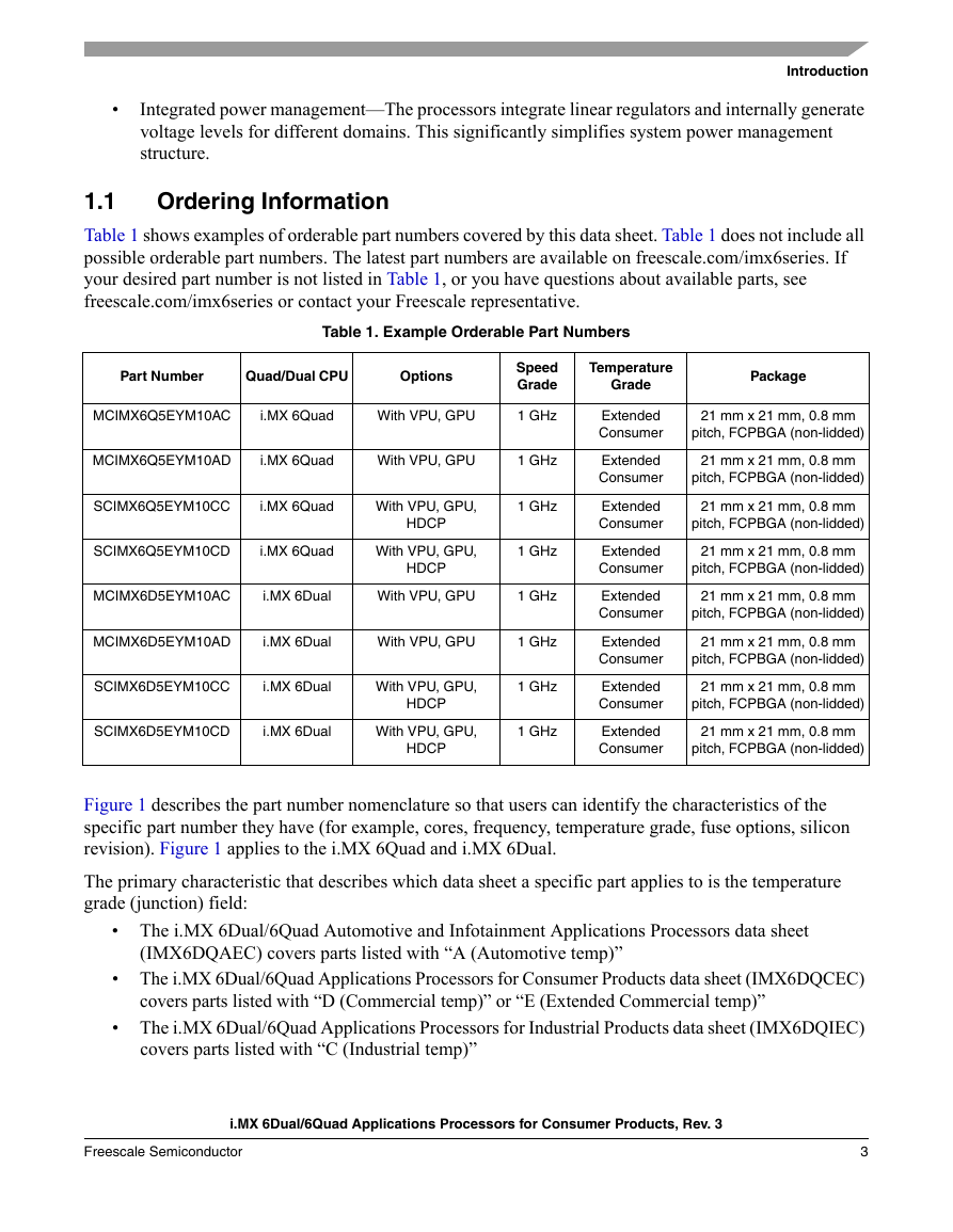
Introduction • Integrated power management—The processors integrate linear regulators and internally generate voltage levels for different domains. This significantly simplifies system power management structure. Ordering Information 1.1 Table 1 shows examples of orderable part numbers covered by this data sheet. Table 1 does not include all possible orderable part numbers. The latest part numbers are available on freescale.com/imx6series. If your desired part number is not listed in Table 1, or you have questions about available parts, see freescale.com/imx6series or contact your Freescale representative. Table 1. Example Orderable Part Numbers Part Number Quad/Dual CPU Options Speed Grade Temperature Grade Package MCIMX6Q5EYM10AC i.MX 6Quad With VPU, GPU 1 GHz MCIMX6Q5EYM10AD i.MX 6Quad With VPU, GPU 1 GHz SCIMX6Q5EYM10CC i.MX 6Quad With VPU, GPU, 1 GHz HDCP SCIMX6Q5EYM10CD i.MX 6Quad With VPU, GPU, 1 GHz HDCP MCIMX6D5EYM10AC i.MX 6Dual With VPU, GPU 1 GHz MCIMX6D5EYM10AD i.MX 6Dual With VPU, GPU 1 GHz SCIMX6D5EYM10CC i.MX 6Dual With VPU, GPU, 1 GHz HDCP SCIMX6D5EYM10CD i.MX 6Dual With VPU, GPU, 1 GHz HDCP Extended Consumer Extended Consumer Extended Consumer Extended Consumer Extended Consumer Extended Consumer Extended Consumer Extended Consumer 21 mm x 21 mm, 0.8 mm pitch, FCPBGA (non-lidded) 21 mm x 21 mm, 0.8 mm pitch, FCPBGA (non-lidded) 21 mm x 21 mm, 0.8 mm pitch, FCPBGA (non-lidded) 21 mm x 21 mm, 0.8 mm pitch, FCPBGA (non-lidded) 21 mm x 21 mm, 0.8 mm pitch, FCPBGA (non-lidded) 21 mm x 21 mm, 0.8 mm pitch, FCPBGA (non-lidded) 21 mm x 21 mm, 0.8 mm pitch, FCPBGA (non-lidded) 21 mm x 21 mm, 0.8 mm pitch, FCPBGA (non-lidded) Figure 1 describes the part number nomenclature so that users can identify the characteristics of the specific part number they have (for example, cores, frequency, temperature grade, fuse options, silicon revision). Figure 1 applies to the i.MX 6Quad and i.MX 6Dual. The primary characteristic that describes which data sheet a specific part applies to is the temperature grade (junction) field: • The i.MX 6Dual/6Quad Automotive and Infotainment Applications Processors data sheet (IMX6DQAEC) covers parts listed with “A (Automotive temp)” • The i.MX 6Dual/6Quad Applications Processors for Consumer Products data sheet (IMX6DQCEC) covers parts listed with “D (Commercial temp)” or “E (Extended Commercial temp)” • The i.MX 6Dual/6Quad Applications Processors for Industrial Products data sheet (IMX6DQIEC) covers parts listed with “C (Industrial temp)” i.MX 6Dual/6Quad Applications Processors for Consumer Products, Rev. 3 Freescale Semiconductor 3
Introduction Ensure that you have the right data sheet for your specific part by checking the temperature grade (junction) field and matching it to the right data sheet. If you have questions, see freescale.com/imx6series or contact your Freescale representative. MC  IMX6 X @ + VV $$ % A Qualification level Prototype Samples Mass Production Special Part # series i.MX 6Quad i.MX 6Dual MC PC MC SC X Q D Part differentiator Industrial – w/ VPU, GPU, no MLB Automotive – w/ VPU, GPU Consumer – w/ VPU, GPU Automotive – w/ GPU, no VPU @ 7 6 5 4 Silicon revision1 Rev 1.2 Rev 1.3 Fusing Default Setting HDCP Enabled Frequency 800 MHz2 (Industrial grade) 852 MHz (Automotive grade) 1 GHz3 1.2 GHz Package type FCPBGA 21x21 0.8mm (lidded) FCPBGA 21x21 0.8mm (non lidded) A C D % A C $$ 08 08 10 12 RoHS VT YM Temperature Tj Extended Commercial: -20 to + 105C Industrial: -40 to +105C Automotive: -40 to + 125C + E C A 1. See the freescale.com\imx6series Web page for latest information on the available silicon revision. 2. If a 24 MHz input clock is used (required for USB), the maximum SoC speed is limited to 792 MHz. 3. If a 24 MHz input clock is used (required for USB), the maximum SoC speed is limited to 996 MHz. Figure 1. Part Number Nomenclature—i.MX 6Quad and i.MX 6Dual Features 1.2 The i.MX 6Dual/6Quad processors are based on ARM Cortex-A9 MPCore platform, which has the following features: • ARM Cortex-A9 MPCore 4xCPU processor (with TrustZone®) • The core configuration is symmetric, where each core includes: — 32 KByte L1 Instruction Cache — 32 KByte L1 Data Cache — Private Timer and Watchdog — Cortex-A9 NEON MPE (Media Processing Engine) Co-processor The ARM Cortex-A9 MPCore complex includes: • General Interrupt Controller (GIC) with 128 interrupt support • Global Timer • Snoop Control Unit (SCU) i.MX 6Dual/6Quad Applications Processors for Consumer Products, Rev. 3 4 Freescale Semiconductor
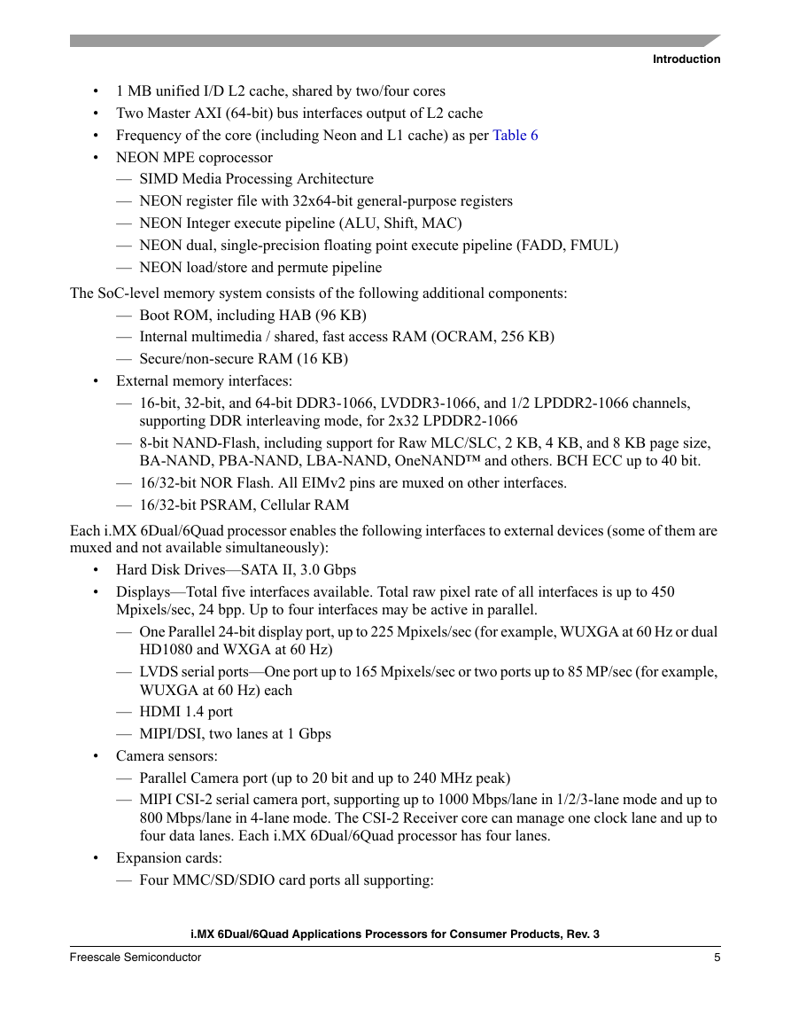
Introduction 1 MB unified I/D L2 cache, shared by two/four cores • • Two Master AXI (64-bit) bus interfaces output of L2 cache • • NEON MPE coprocessor Frequency of the core (including Neon and L1 cache) as per Table 6 — SIMD Media Processing Architecture — NEON register file with 32x64-bit general-purpose registers — NEON Integer execute pipeline (ALU, Shift, MAC) — NEON dual, single-precision floating point execute pipeline (FADD, FMUL) — NEON load/store and permute pipeline The SoC-level memory system consists of the following additional components: — Boot ROM, including HAB (96 KB) — Internal multimedia / shared, fast access RAM (OCRAM, 256 KB) — Secure/non-secure RAM (16 KB) • External memory interfaces: — 16-bit, 32-bit, and 64-bit DDR3-1066, LVDDR3-1066, and 1/2 LPDDR2-1066 channels, supporting DDR interleaving mode, for 2x32 LPDDR2-1066 — 8-bit NAND-Flash, including support for Raw MLC/SLC, 2 KB, 4 KB, and 8 KB page size, BA-NAND, PBA-NAND, LBA-NAND, OneNAND™ and others. BCH ECC up to 40 bit. — 16/32-bit NOR Flash. All EIMv2 pins are muxed on other interfaces. — 16/32-bit PSRAM, Cellular RAM Each i.MX 6Dual/6Quad processor enables the following interfaces to external devices (some of them are muxed and not available simultaneously): • Hard Disk Drives—SATA II, 3.0 Gbps • Displays—Total five interfaces available. Total raw pixel rate of all interfaces is up to 450 Mpixels/sec, 24 bpp. Up to four interfaces may be active in parallel. — One Parallel 24-bit display port, up to 225 Mpixels/sec (for example, WUXGA at 60 Hz or dual HD1080 and WXGA at 60 Hz) — LVDS serial ports—One port up to 165 Mpixels/sec or two ports up to 85 MP/sec (for example, WUXGA at 60 Hz) each — HDMI 1.4 port — MIPI/DSI, two lanes at 1 Gbps • Camera sensors: — Parallel Camera port (up to 20 bit and up to 240 MHz peak) — MIPI CSI-2 serial camera port, supporting up to 1000 Mbps/lane in 1/2/3-lane mode and up to 800 Mbps/lane in 4-lane mode. The CSI-2 Receiver core can manage one clock lane and up to four data lanes. Each i.MX 6Dual/6Quad processor has four lanes. • Expansion cards: — Four MMC/SD/SDIO card ports all supporting: i.MX 6Dual/6Quad Applications Processors for Consumer Products, Rev. 3 Freescale Semiconductor 5
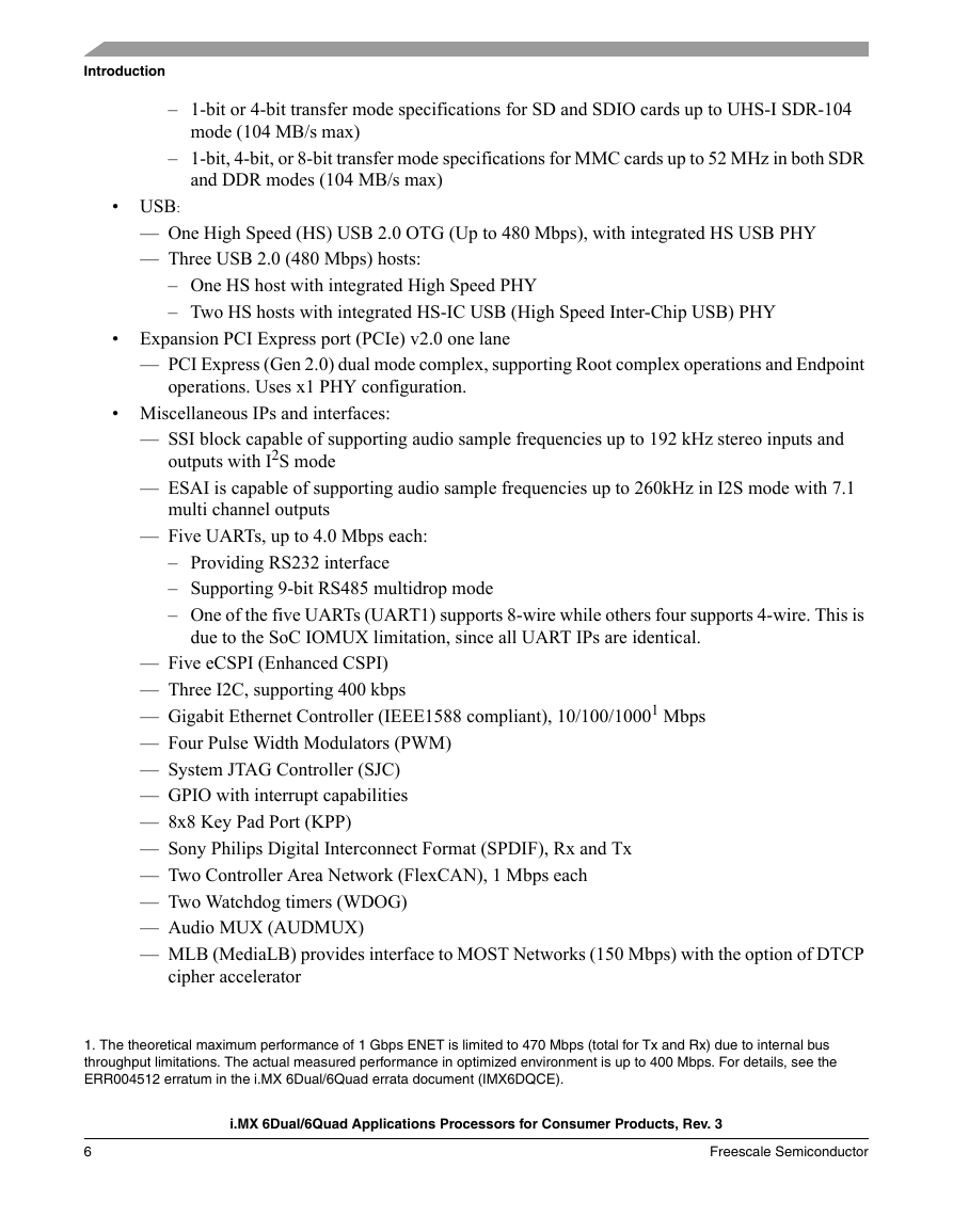
Introduction – 1-bit or 4-bit transfer mode specifications for SD and SDIO cards up to UHS-I SDR-104 mode (104 MB/s max) – 1-bit, 4-bit, or 8-bit transfer mode specifications for MMC cards up to 52 MHz in both SDR and DDR modes (104 MB/s max) • USB: — One High Speed (HS) USB 2.0 OTG (Up to 480 Mbps), with integrated HS USB PHY — Three USB 2.0 (480 Mbps) hosts: – One HS host with integrated High Speed PHY – Two HS hosts with integrated HS-IC USB (High Speed Inter-Chip USB) PHY • Expansion PCI Express port (PCIe) v2.0 one lane — PCI Express (Gen 2.0) dual mode complex, supporting Root complex operations and Endpoint operations. Uses x1 PHY configuration. • Miscellaneous IPs and interfaces: — SSI block capable of supporting audio sample frequencies up to 192 kHz stereo inputs and outputs with I2S mode — ESAI is capable of supporting audio sample frequencies up to 260kHz in I2S mode with 7.1 multi channel outputs — Five UARTs, up to 4.0 Mbps each: – Providing RS232 interface – Supporting 9-bit RS485 multidrop mode – One of the five UARTs (UART1) supports 8-wire while others four supports 4-wire. This is due to the SoC IOMUX limitation, since all UART IPs are identical. — Five eCSPI (Enhanced CSPI) — Three I2C, supporting 400 kbps — Gigabit Ethernet Controller (IEEE1588 compliant), 10/100/10001 Mbps — Four Pulse Width Modulators (PWM) — System JTAG Controller (SJC) — GPIO with interrupt capabilities — 8x8 Key Pad Port (KPP) — Sony Philips Digital Interconnect Format (SPDIF), Rx and Tx — Two Controller Area Network (FlexCAN), 1 Mbps each — Two Watchdog timers (WDOG) — Audio MUX (AUDMUX) — MLB (MediaLB) provides interface to MOST Networks (150 Mbps) with the option of DTCP cipher accelerator 1. The theoretical maximum performance of 1 Gbps ENET is limited to 470 Mbps (total for Tx and Rx) due to internal bus throughput limitations. The actual measured performance in optimized environment is up to 400 Mbps. For details, see the ERR004512 erratum in the i.MX 6Dual/6Quad errata document (IMX6DQCE). i.MX 6Dual/6Quad Applications Processors for Consumer Products, Rev. 3 6 Freescale Semiconductor
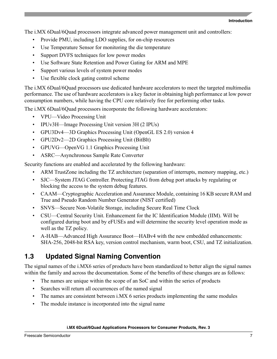
The i.MX 6Dual/6Quad processors integrate advanced power management unit and controllers: Introduction Support DVFS techniques for low power modes Provide PMU, including LDO supplies, for on-chip resources • • Use Temperature Sensor for monitoring the die temperature • • Use Software State Retention and Power Gating for ARM and MPE • • Use flexible clock gating control scheme Support various levels of system power modes The i.MX 6Dual/6Quad processors use dedicated hardware accelerators to meet the targeted multimedia performance. The use of hardware accelerators is a key factor in obtaining high performance at low power consumption numbers, while having the CPU core relatively free for performing other tasks. The i.MX 6Dual/6Quad processors incorporate the following hardware accelerators: IPUv3H—Image Processing Unit version 3H (2 IPUs) • VPU—Video Processing Unit • • GPU3Dv4—3D Graphics Processing Unit (OpenGL ES 2.0) version 4 • GPU2Dv2—2D Graphics Processing Unit (BitBlt) • GPUVG—OpenVG 1.1 Graphics Processing Unit • ASRC—Asynchronous Sample Rate Converter Security functions are enabled and accelerated by the following hardware: • ARM TrustZone including the TZ architecture (separation of interrupts, memory mapping, etc.) • SJC—System JTAG Controller. Protecting JTAG from debug port attacks by regulating or blocking the access to the system debug features. • CAAM—Cryptographic Acceleration and Assurance Module, containing 16 KB secure RAM and True and Pseudo Random Number Generator (NIST certified) SNVS—Secure Non-Volatile Storage, including Secure Real Time Clock • • CSU—Central Security Unit. Enhancement for the IC Identification Module (IIM). Will be configured during boot and by eFUSEs and will determine the security level operation mode as well as the TZ policy. • A-HAB—Advanced High Assurance Boot—HABv4 with the new embedded enhancements: SHA-256, 2048-bit RSA key, version control mechanism, warm boot, CSU, and TZ initialization. Updated Signal Naming Convention 1.3 The signal names of the i.MX6 series of products have been standardized to better align the signal names within the family and across the documentation. Some of the benefits of these changes are as follows: Searches will return all occurrences of the named signal • The names are unique within the scope of an SoC and within the series of products • • The names are consistent between i.MX 6 series products implementing the same modules • The module instance is incorporated into the signal name i.MX 6Dual/6Quad Applications Processors for Consumer Products, Rev. 3 Freescale Semiconductor 7
Introduction This change applies only to signal names. The original ball names have been preserved to prevent the need to change schematics, BSDL models, IBIS models, etc. Throughout this document, the updated signal names are used except where referenced as a ball name (such as the Functional Contact Assignments table, Ball Map table, and so on). A master list of the signal name changes is in the document, IMX 6 Series Signal Name Mapping (EB792). This list can be used to map the signal names used in older documentation to the new standardized naming conventions. i.MX 6Dual/6Quad Applications Processors for Consumer Products, Rev. 3 8 Freescale Semiconductor
分享到:
收藏