Abaqus 6.10 PDF Documentation
Abaqus Theory Manual
Legal Notices
Locations
Preface
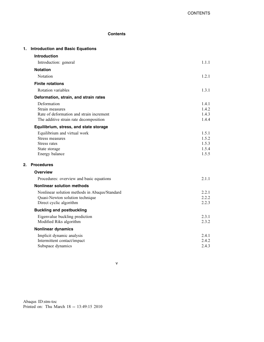
Contents
1. Introduction and Basic Equations
1.1 Introduction
1.1.1 Introduction: general
1.2 Notation
1.2.1 Notation
Basic quantities
Basic operations
Components of a vector or a matrix in a coordinate system
Components of a derivative
Virtual quantities
Initial and current positions
Nodal variables
1.3 Finite rotations
1.3.1 Rotation variables
Quaternion parametrization
Compound rotations
Rotation vector extraction
Director and rotation field updates
Variations of the rotation field
Velocity and acceleration
Coupling of rotations: constant velocity joint
Reference
1.4 Deformation, strain, and strain rates
1.4.1 Deformation
Reference
1.4.2 Strain measures
Strain in one dimension
Strain in general three-dimensional motions
Reference
1.4.3 Rate of deformation and strain increment
Reference
1.4.4 The additive strain rate decomposition
Reference
1.5 Equilibrium, stress, and state storage
1.5.1 Equilibrium and virtual work
Reference
1.5.2 Stress measures
Reference
1.5.3 Stress rates
Stress rates used in Abaqus
Reference
1.5.4 State storage
Reference
1.5.5 Energy balance
References
2. Procedures
2.1 Overview
2.1.1 Procedures: overview and basic equations
Basic finite element equations
Reference
2.2 Nonlinear solution methods
2.2.1 Nonlinear solution methods in Abaqus/Standard
References
2.2.2 Quasi-Newton solution technique
Reference
2.2.3 Direct cyclic algorithm
Reference
2.3 Buckling and postbuckling
2.3.1 Eigenvalue buckling prediction
Reference
2.3.2 Modified Riks algorithm
Basic variable definitions
Reference
2.4 Nonlinear dynamics
2.4.1 Implicit dynamic analysis
Reference
2.4.2 Intermittent contact/impact
Reference
2.4.3 Subspace dynamics
Reference
2.4.4 Equivalent rigid body dynamic motion
Reference
2.4.5 Explicit dynamic analysis
Stability
Bulk viscosity
Rotational bulk viscosity for shell elements
Reference
2.5 Modal dynamics
2.5.1 Eigenvalue extraction
Eigenvalue extraction for symmetric systems
Subspace iteration—the basic algorithm
Lanczos eigensolver
The Householder method with quarter rotation
Complex eigenvalue extraction
Subspace projection method
References
2.5.2 Variables associated with the natural modes of a model
Generalized mass
Modal participation factors
Modal effective mass
Composite modal damping
References
2.5.3 Linear dynamic analysis using modal superposition
Reference
2.5.4 Damping options for modal dynamics
Critical damping factors
Rayleigh damping
Composite modal damping
Structural damping
Reference
2.5.5 Modal dynamic analysis
Solution to the uncoupled system
Solution to the coupled system
Integral coefficients
Damping less than critical
Damping equal to critical
Damping higher than critical
Rigid body mode with damping
Rigid body mode without damping
Structural damping in modal dynamic analysis
Response of nodal and element variables
Initial conditions
Base motion definition
Reference
2.5.6 Response spectrum analysis
Reference
2.5.7 Steady-state linear dynamic analysis
Reference
2.5.8 Random response analysis
Statistical measures
Correlation
Fourier transforms
Cross-spectral density
Random response analysis
The frequency response function
Response development
Decibel conversion
von Mises stress computation
Reference
2.5.9 Base motions in modal-based procedures
Primary base motions
Secondary base motions
References
2.6 Complex harmonic oscillations
2.6.1 Direct steady-state dynamic analysis
Reference
2.6.2 Subspace-based steady-state dynamic analysis
Output
Reference
2.7 Steady-state transport analysis
2.7.1 Steady-state transport analysis
Kinematics of steady-state rolling
Inertia
Performing a harmonic analysis about a nonlinear base state
Contact conditions
Reference
2.8 Analysis of porous media
2.8.1 Effective stress principle for porous media
References
2.8.2 Discretized equilibrium statement for a porous medium
References
2.8.3 Constitutive behavior in a porous medium
Liquid response
Grains response
Liquid entrapment
Effective strain
Reference
2.8.4 Continuity statement for the wetting liquid phase in a porous medium
Constitutive behavior
Volumetric strain in the liquid and grains
Saturation
Jacobian contribution
References
2.8.5 Solution strategy for coupled diffusion/deformation
Reference
2.9 Coupled fluid-solid analysis
2.9.1 Coupled acoustic-structural medium analysis
Acoustic equations
Physical boundary conditions in acoustic analysis
Formulation for direct integration transient dynamics
Variational statement
The discretized finite element equations
Time integration
Summary of additional approximations of the direct integration transient formulation
Formulation for steady-state response using nodal degrees of freedom
Variational statement
The discretized finite element equations
Formulation for eigenvalue extraction and mode-based procedures
Lanczos formulation
Frequency-domain solution using projections onto modal spaces
Using uncoupled Abaqus/AMS modes
Volumetric drag and fluid viscosity
Acoustic output quantities
Acoustic contribution factors
Impedance and admittance at fluid boundaries
Radiation boundary conditions
An improvement on radiation boundary conditions for plane waves
References
2.10 Piezoelectric analysis
2.10.1 Piezoelectric analysis
Equilibrium and flux conservation
Constitutive behavior: material coupling
Kinematics
System equations
Reference
2.11 Heat transfer
2.11.1 Uncoupled heat transfer analysis
Energy balance
Constitutive definition
Boundary conditions
Spatial discretization
Time integration
Reference
2.11.2 Shell heat conduction
Reference
2.11.3 Convection/diffusion
Thermal equilibrium equation
Reference
2.11.4 Cavity radiation
Thermal radiation
Spatial interpolation
Cavity radiation flux and Jacobian contributions
Reference
2.11.5 Viewfactor calculation
Viewfactor between elementary areas
Discretization
Radiation blocking
Radiation symmetries
Viewfactor checking
Radiation to ambient
References
2.12 Coupled thermal-electrical analysis
2.12.1 Coupled thermal-electrical analysis
Governing equations
Constitutive behavior
Thermal energy balance
Thermal energy due to electrical current
Surface conditions
Spatial discretization
Jacobian contributions
Reference
2.13 Mass diffusion
2.13.1 Mass diffusion analysis
Governing equations
Constitutive behavior
Discretization and time integration
Jacobian contribution
Reference
2.14 Substructuring
2.14.1 Substructuring and substructure analysis
Large-rotation substructures
Fixed direction gravity loading
Reference
2.15 Submodeling
2.15.1 Submodeling analysis
Node-based submodeling
Interpolation procedure and tolerance checking
Driven variables for shell-to-solid submodeling
Surface-based submodeling
Interpolation procedure and tolerance checking
Stress solution smoothing
Surface traction determination
References
2.16 Fracture mechanics
2.16.1 J -integral evaluation
J -integral in two dimensions
J -integral in three dimensions
Reference
2.16.2 Stress intensity factor extraction
Interaction integral method
Reference
2.16.3 T -stress extraction
Reference
2.16.4 Prediction of the direction of crack propagation
Maximum tangential stress criterion
Maximum energy release rate criterion
K II = 0 criterion
Reference
2.17 Stress linearization
2.17.1 Stress linearization
Computing the stress components
Three-dimensional structures
Axisymmetric structures
Meridional stress
Hoop stress
Thickness stress
Shear stress
Curvature correction in nonaxisymmetric structures
Computing the local coordinate system
Axisymmetric case
Three-dimensional case
Reference
2.18 Design sensitivity analysis
2.18.1 Design sensitivity analysis
DSA for static stress analysis
Total displacement DSA formulation for nonlinear equilibrium problems
Incremental displacement DSA formulation for history-dependent equilibrium problems
Computational approach
DSA for frequency analysis
Distinct eigenvalue case
Repeated eigenvalue case
Computational approach
Choosing the finite difference interval
Reference
3. Elements
3.1 Overview
3.1.1 Element library: overview
Reference
3.2 Continuum elements
3.2.1 Solid element overview
Reference
3.2.2 Solid element formulation
Reference
3.2.3 Hybrid incompressible solid element formulation
Reference
3.2.4 Solid isoparametric quadrilaterals and hexahedra
Interpolation
Integration of homogeneous solids
Fully integrated first-order isoparametric elements
Integration of composite solids
Reference
3.2.5 Continuum elements with incompatible modes
Geometrically linear formulation
Geometrically nonlinear formulation
Reference
3.2.6 Triangular, tetrahedral, and wedge elements
Interpolation
Integration
Reference
3.2.7 Generalized plane strain elements
References
3.2.8 Axisymmetric elements
Kinematic description
Parametric interpolation and integration
Deformation gradient
Virtual work
Stiffness in the current state
Reference
3.2.9 Axisymmetric elements allowing nonlinear bending
Interpolation
Integration
Deformation gradient
Strain and rotation increments
Virtual work
Stiffness in the current state
Hourglass control
Pressure loads and load stiffness
Mass matrix
Hybrid and pore pressure elements
Pore pressure gradient
Reference
3.3 Infinite elements
3.3.1 Solid infinite elements
Static analysis
Dynamic response
Reference
3.3.2 Acoustic infinite elements
Transient formulation
Steady-state analysis
Lateral face terms due to impedance conditions
Coupling between acoustic and solid infinite elements
References
3.4 Membrane and truss elements
3.4.1 Membrane elements
Equilibrium
Jacobian
Thickness change
Total deformation
Reference
3.4.2 Truss elements
Interpolation
Strain measure
First variation of strain
Second variation of strain
Integration
Virtual work contribution
Mixed (hybrid) forms
Reference
3.4.3 Axisymmetric membranes
Kinematic description
Parametric interpolation and integration
Deformation gradient
Virtual work
Stiffness in the current state
Reference
3.5 Beam elements
3.5.1 Beam element overview
Reference
3.5.2 Beam element formulation
Beam element in undeformed configuration
Change of position, warping, and normal direction
Change of curvature and twist
First variations
Solution with Newton's algorithm
Second variations
Strains
Virtual work
The rate of change of virtual work
Section integration
Beams with unconstrained warping
Beams with elastic torsion and constrained warping
Circular section
Solid noncircular sections
Closed, thin walled cross-sections
Thin walled open sections
Reference
3.5.3 Euler-Bernoulli beam elements
Strain measures
Internal virtual work rate Jacobian
First variations of strains
Second variations of strains
Interpolation
Integration
Reference
3.5.4 Hybrid beam elements
Axial and bending behavior
Transverse shear
Reference
3.5.5 Mass and inertia for Timoshenko beams
3.5.6 Meshed beam cross-sections
Overview
Defining the shear center and warping function
3.6 Shell elements
3.6.1 Shell element overview
Thickness change
Reference
3.6.2 Axisymmetric shell elements
Interpolation and integration
Theory
Reference
3.6.3 Shear flexible small-strain shell elements
Notation
Surface measures
Displacements
Interpolation
Strains
Penalties
First variations of strain
Second variations of strains
Internal virtual work rate
Pressure load stiffness
Reference
3.6.4 Triangular facet shell elements
Kinematics
First variations of strain
Second variations of strain
Internal virtual work rate
Reference
3.6.5 Finite-strain shell element formulation
Geometric description
Parametric interpolation
Membrane deformation and curvature
Orientation update
Curvature change
Deformation gradient
Membrane strain increment
Curvature increment
Virtual work
The rate of virtual work
Second variation of the membrane strain
Second variation of the curvature
Transverse shear treatment
Construction of the assumed strain field
Constitutive relations
Initial stress stiffness
One point integration plus stabilization
Comments on stabilization
In-plane displacement hourglass control
Rotational hourglass control
Degenerate elements
Rotary inertia scaling for explicit dynamics
Rotary inertia scaling
Rotational bulk viscosity for explicit dynamics
Fully integrated finite-membrane-strain shell formulation
Patch test
References
3.6.6 Small-strain shell elements in Abaqus/Explicit
Corotational coordinate system
Velocity strain formulation
Small-strain element S4RS
Small-strain element S4RSW
Small-strain element S3RS
Hourglass control
Reference
3.6.7 Axisymmetric shell element allowing asymmetric loading
Geometric description
Interpolations
Virtual work
Orthonormal surface coordinate system and coordinate transformation
Strain displacement operators
Corotational coordinate system
Consistent linearization
Incremental degrees of freedom: interpolations and configuration updates
Strain increment and stress resultant update
Pressure loads and load stiffness
Penalty constraints: transverse shear and drill rotation
Transverse shear
Drill rotation
Zero radius: collapsed edge
Mass matrix
Reference
3.6.8 Transverse shear stiffness in composite shells and offsets from the midsurface
Transverse shear stiffness
Finite-strain shells
Small-strain shells
Offset: reference surface versus midsurface
Reference
3.6.9 Rotary inertia for 5 degree of freedom shell elements
Reference
3.7 Rebar
3.7.1 Rebar modeling in two dimensions
Reference
3.7.2 Rebar modeling in three dimensions
Reference
3.7.3 Rebar modeling in shell, membrane, and surface elements
Reference
3.8 Hydrostatic fluid elements
3.8.1 Hydrostatic fluid elements
Hydraulic fluid with thermal expansion
Ideal gas
Volume calculation
Fluid link element
Negative eigenvalues
Reference
3.9 Special-purpose elements
3.9.1 Elbow elements
Geometric definitions
Interpolation
Pipe axis quantities
Cross-sectional deformation quantities
Strains and constraint
Some simplifying approximations
Reference
3.9.2 Frame elements with lumped plasticity
Degrees of freedom on the element
The elastic formulation
Lumped plasticity model
The hardening model
Plastic interaction surface
Large-displacement and large-rotation formulation
Additional data
Reference
3.9.3 Buckling strut response for frame elements
Buckling prediction and the ISO equation
Marshall strut envelope
References
3.9.4 Tube support elements
Geometry and kinematics
Forces in the element
Reference
3.9.5 Line spring elements
Virtual work contribution
Interpolation
Elasticity
Plasticity
Reference
3.9.6 Flexible joint element
Kinematics
Virtual work
Reference
3.9.7 Rotary inertia element
Reference
3.9.8 Distributing coupling elements
Load distribution
Constraint expression
Finite motion
Virtual work contribution
Initial stress stiffness terms
Mass
References
4. Mechanical Constitutive Theories
4.1 Overview
4.1.1 Mechanical constitutive models
Reference
4.2 Plasticity overview
4.2.1 Plasticity models: general discussion
Reference
4.2.2 Integration of plasticity models
Tangent matrix
Reference
4.3 Metal plasticity
4.3.1 Metal plasticity models
Reference
4.3.2 Isotropic elasto-plasticity
Material model definition
Plane stress
Uniaxial stress
Material stiffness
Plane stress
Uniaxial stress
Reference
4.3.3 Stress potentials for anisotropic metal plasticity
Reference
4.3.4 Rate-dependent metal plasticity (creep)
User subroutine CREEP
Reference
4.3.5 Models for metals subjected to cyclic loading
Strain rate decomposition
Elastic behavior
Plastic behavior
Linear kinematic hardening model
Nonlinear isotropic/kinematic hardening model
Reference
4.3.6 Porous metal plasticity
Yield condition
Flow rule
Evolution of the plastic strains and f
Integration of the elastoplastic equations
Computing the linearization moduli
Reference
4.3.7 Cast iron plasticity
Strain rate decomposition
Elastic behavior
Yield condition
Flow rule
Hardening
Reference
4.3.8 ORNL constitutive theory
ORNL plasticity theory of stainless steel
ORNL creep theory for stainless steel
Reference
4.3.9 Deformation plasticity
One-dimensional model
Multiaxial generalization
Strain energy density
Stress solution
The uniaxial case (the only nonzero stress component is one direct stress)
All strain components defined by the kinematic solution
Plane stress
Reference
4.3.10 Heat generation caused by plastic straining
References
4.4 Plasticity for non-metals
4.4.1 Porous elasticity
Reference
4.4.2 Models for granular or polymer behavior
Available yield criteria
Hardening, rate dependence, and creep
Strain rate decomposition
Elastic behavior
Linear Drucker-Prager model
Flow rule
Hyperbolic and general exponent models
Flow rule
Creep models
Creep behavior
Creep flow rule
Reference
4.4.3 Critical state models
The strain rate decomposition
Elastic behavior
Plastic behavior
Reference
4.4.4 Drucker-Prager/Cap model for geological materials
Strain rate decomposition
Elastic behavior
Plastic behavior
Flow rule
Creep model
Creep behavior
Creep flow rule
Cohesion creep
Consolidation creep
Reference
4.4.5 Mohr-Coulomb model
Strain rate decomposition
Elastic behavior
Yield behavior
Flow rule
Reference
4.4.6 Models for crushable foams
The strain rate decomposition
Elastic behavior
Plastic behavior
Crushable foam model with volumetric hardening
Yield surface
Flow potential
Hardening
Crushable foam model with isotropic hardening
Yield surface
Flow potential
Hardening
Reference
4.5 Other inelastic models
4.5.1 An inelastic constitutive model for concrete
Elastic-plastic model for concrete
Strain rate decomposition
Compression yield
Hardening
Flow
Crack detection and damaged elasticity
Strain rate decomposition
Yield
Flow
Hardening
Damaged elasticity
Cracking
Integration of the model
Reference
4.5.2 Damaged plasticity model for concrete and other quasi-brittle materials
Overview
Strain rate decomposition
Stress-strain relations
Hardening variables
Yield function
Flow rule
Summary
Damage and stiffness degradation
Uniaxial conditions
Uniaxial cyclic conditions
Multiaxial conditions
Elastic stiffness degradation
Yield condition
Flow rule
Viscoplastic regularization
Integration of the model
4.5.3 A cracking model for concrete and other brittle materials
Smeared cracking assumption
Crack direction assumptions
Elastic-cracking model for concrete
Strain rate decomposition
Crack direction transformations
Elasticity
Crack detection
Cracking conditions
Cracking relation
Rate constitutive equations
Tension softening models
Cracked shear models
Reference
4.5.4 Constitutive model for jointed materials
Joint system definitions
Strain rate decomposition
Elasticity and joint opening/closing
Plastic behavior of joint systems
Plastic behavior of bulk material
Integration of the model
Reference
4.6 Large-strain elasticity
4.6.1 Hyperelastic material behavior
Definitions and basic kinematic results
Rate of change of the internal virtual work
Particular forms of the strain energy potential
Polynomial form and particular cases
Ogden form
Arruda-Boyce form
Van der Waals form
Strain energy potential for highly compressible elastomers
Subroutine UHYPER
References
4.6.2 Fitting of hyperelastic and hyperfoam constants
Stress-strain relations for the polynomial strain energy potential
Uniaxial mode
Equibiaxial mode
Planar (pure shear) mode
Volumetric mode
Stress-strain relations for the reduced polynomial strain energy potential
Uniaxial mode
Equibiaxial mode
Planar (pure shear) mode
Volumetric mode
Stress-strain relations for the hyperelastic Ogden strain energy potential
Uniaxial mode
Equibiaxial mode
Planar (pure shear) mode
Volumetric mode
Stress-strain relations for the hyperelastic Arruda-Boyce strain energy potential
Uniaxial mode
Equibiaxial mode
Planar (pure shear) mode
Volumetric mode
Stress-strain relations for the hyperelastic Van der Waals energy potential
Uniaxial mode
Equibiaxial mode
Planar (pure shear) mode
Volumetric mode
Stress-strain relations for the hyperfoam strain energy potential
Uniaxial mode
Equibiaxial mode
Planar mode
Simple shear mode
Volumetric mode
Least squares fit
Linear least squares fit for the polynomial model
Linear least squares fit for the reduced polynomial model
Nonlinear least squares fit
Nonlinear least squares fit for the Ogden model
Nonlinear least squares fit for the Arruda-Boyce model
Nonlinear least squares fit for the Van der Waals model
Drucker stability check
Polynomial form
Ogden form
Arruda-Boyce form
Van der Waals form
Hyperfoam
References
4.6.3 Anisotropic hyperelastic material behavior
Strain-based formulation
Invariant-based formulation
Particular forms of the strain energy potential
Generalized Fung form
Holzapfel-Gasser-Ogden form
User-defined form: strain-based
User-defined form: invariant-based
Reference
4.7 Mullins effect and permanent set
4.7.1 Mullins effect
Material behavior
Idealized material behavior
Basic framework for the model
Primary hyperelastic behavior
Augmented strain energy density function
Stress computation
Damage function and damage variable
Material tangent stiffness
Damage dissipation
Reference
4.7.2 Permanent set
Approach used
Reference
4.8 Viscoelasticity
4.8.1 Viscoelasticity
Reduced states of stress
Automatic time stepping procedure
Reference
4.8.2 Finite-strain viscoelasticity
Integral formulation
Implementation
Integration of the hydrostatic stress
Integration of the deviatoric stress
Rate equation
Cauchy versus Kirchhoff stress
Reference
4.8.3 Frequency domain viscoelasticity
Reference
4.9 Hysteresis
4.9.1 Hysteresis
Reference
5. Interface Modeling
5.1 Contact modeling
5.1.1 Small-sliding interaction between bodies
Identification of tangent plane based on nearest neighbor interaction
Contact formulation as a constrained variational principle
Formulation for two-dimensional small-sliding deformable contact
Formulation for three-dimensional small-sliding deformable contact
Formulation for two-dimensional small-sliding rigid contact
Formulation for three-dimensional small-sliding rigid contact
Reference
5.1.2 Finite-sliding interaction between deformable bodies
Two-dimensional and axisymmetric slide line elements
Tube-tube interface elements
Slide line smoothing
Self contact
References
5.1.3 Finite-sliding interaction between a deformable and a rigid body
Reference
5.2 Surface interactions
5.2.1 Contact pressure definition
Hard contact
Softened contact defined with an exponential pressure-overclosure relationship
Softened contact defined with a tabular pressure-overclosure relationship
Softened contact defined with a linear pressure-overclosure relationship
Softened contact implementation
Viscous damping option
Reference
5.2.2 Pressure and fluid flow in pore pressure contact
The pore fluid constraints on the contact interface
The transient equations
Closed contact
The steady-state equations
Small sliding
Reference
5.2.3 Coulomb friction
Elastic stick formulation
Frictional stress due to forced sliding in static analysis
Friction contributions for complex eigenvalue extraction analysis
Viscous stick formulation for steady-state transport
Exact stick formulation
Anisotropic friction
Viscous damping
Reference
5.2.4 Thermal interface definition
Conduction
Radiation
Jacobian matrix
Reference
5.2.5 Heat generation caused by frictional sliding
References
5.2.6 Heat generation caused by electrical current
References
5.2.7 Surface-based acoustic-structural medium interaction
The equations on the contact interface between the structure and the acoustic medium
Solid/structural master, fluid slave
Fluid master, solid/structural slave
Reference
6. Loading and Constraints
6.1 Dynamic loading
6.1.1 Centrifugal, Coriolis, and rotary acceleration forces
Reference
6.1.2 Baseline correction of accelerograms
Reference
6.2 Abaqus/Aqua loading
6.2.1 Drag, inertia, and buoyancy loading
Continuously distributed drag and inertia loading
Point drag and inertia loading
Distributed buoyancy
Point buoyancy
Load stiffness
Reference
6.2.2 Airy wave theory
Reference
6.2.3 Stokes wave theory
Fluid particle velocities and accelerations for Stokes 5th order wave
Reference
6.3 Incident wave loading
6.3.1 Loading due to an incident dilatational wave field
Scattering formulation
Virtual mass formulation
Scattering load amplitude
Steady-state dynamics
Effect of structural motion
Underwater explosion—bubble load amplitude
Geers-Hunter model
“Waveless” model
Reflections outside the computational domain
Spherical waves
“Soft” and “hard” limits
Planar waves
Reference
6.4 Pressure penetration loading
6.4.1 Pressure penetration loading with surface-based contact
Reference
6.5 Load stiffness
6.5.1 Pressure load stiffness
Pressure load stiffness on a surface in three-dimensional space
Pressure load stiffness on a surface in two-dimensional space
Reference
6.5.2 Load stiffness for beam elements
Reference
6.5.3 Pressure loadings on elbow elements
Reference
6.6 Multi-point constraints
6.6.1 Sliding constraint
Reference
6.6.2 Shell to solid constraint
Reference
6.6.3 Revolute joint
Reference
6.6.4 Universal joint
Reference
6.6.5 Local velocity constraint
Reference
6.6.6 Kinematic coupling
Rotations
Translations
Linearized form
Second-order form
Reference
7. References
7.1 References
7.1.1





 2023年江西萍乡中考道德与法治真题及答案.doc
 2012年重庆南川中考生物真题及答案.doc
 2013年江西师范大学地理学综合及文艺理论基础考研真题.doc
 2020年四川甘孜小升初语文真题及答案I卷.doc
 2020年注册岩土工程师专业基础考试真题及答案.doc
 2023-2024学年福建省厦门市九年级上学期数学月考试题及答案.doc
 2021-2022学年辽宁省沈阳市大东区九年级上学期语文期末试题及答案.doc
 2022-2023学年北京东城区初三第一学期物理期末试卷及答案.doc
 2018上半年江西教师资格初中地理学科知识与教学能力真题及答案.doc
 2012年河北国家公务员申论考试真题及答案-省级.doc
 2020-2021学年江苏省扬州市江都区邵樊片九年级上学期数学第一次质量检测试题及答案.doc
 2022下半年黑龙江教师资格证中学综合素质真题及答案.doc