实 验 报 告
课程名称:
CPLD/FPGA 应用开发技术
实验名称:
扫描驱动显示电路设计
实验类型: 验证性□ 综合性□ 设计性■
实验室名称:
姓 名 :
组 别 :
\
同 组 人 :
\
成 绩 :
实 验 日 期 :
2010 年 7 月 6 日
预习报告成绩:
指导教师审核(签名):
年
月 日
一、实验目的
预 习 报 告
�
1. 了解实验箱中 8 位七段数码管显示模块的工作原理。
2. 熟悉 VHDL 硬件描述语言及设计专用数字集成电路的自顶向下的设计思想。
3. 掌握利用 CPLD/FPGA 设计 8 位七段数码管扫描显示驱动电路的方法。
二、实验设备
1. 计算机(配置为:P4 CPU 128M 内存);
2. MAX+plus Ⅱ开发工具软件;
3. EL 教学实验箱;
4. 万用表;
5. DS 5022M 型双踪数字示波器;
三、扫描原理
为了减少 8 位显示信号的接口连接线,实验箱中的数码显示采用扫描显示工作模式。
即 8 位数码管的七段译码输入(a,b,c,d,e,f,g) 是并联在一起的,而每一个数码管是通过一个
位选择 sel[2..0]来选定的。sel 与数码管之间是一 3-8 译码的关系,即 sel 为“000” 时,选中
第一个数码管,sel 为“111” 时,选中第八个数码管。
四、设计任务
本实验要求在给定子模块程序的基础上,画出设计原理图。自行编写顶层模块程序,完
成扫描显示驱动电路的设计,实现在 8 个数码管上轮流显示字符 0-F 的功能。
五、设计要求
1.要求在 Max+plusⅡ平台上用 VHDL 语言编写顶层模块程序,调试、仿真成功后,下
载至 ALTER EPM7128SLC84-15 芯片,再利用外接电路实现以上设计功能。
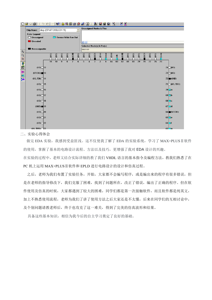
2.扫描驱动显示电路有 2 个输入端(clk,reset),14 个输出端(a,b,c,d,e,f,g)
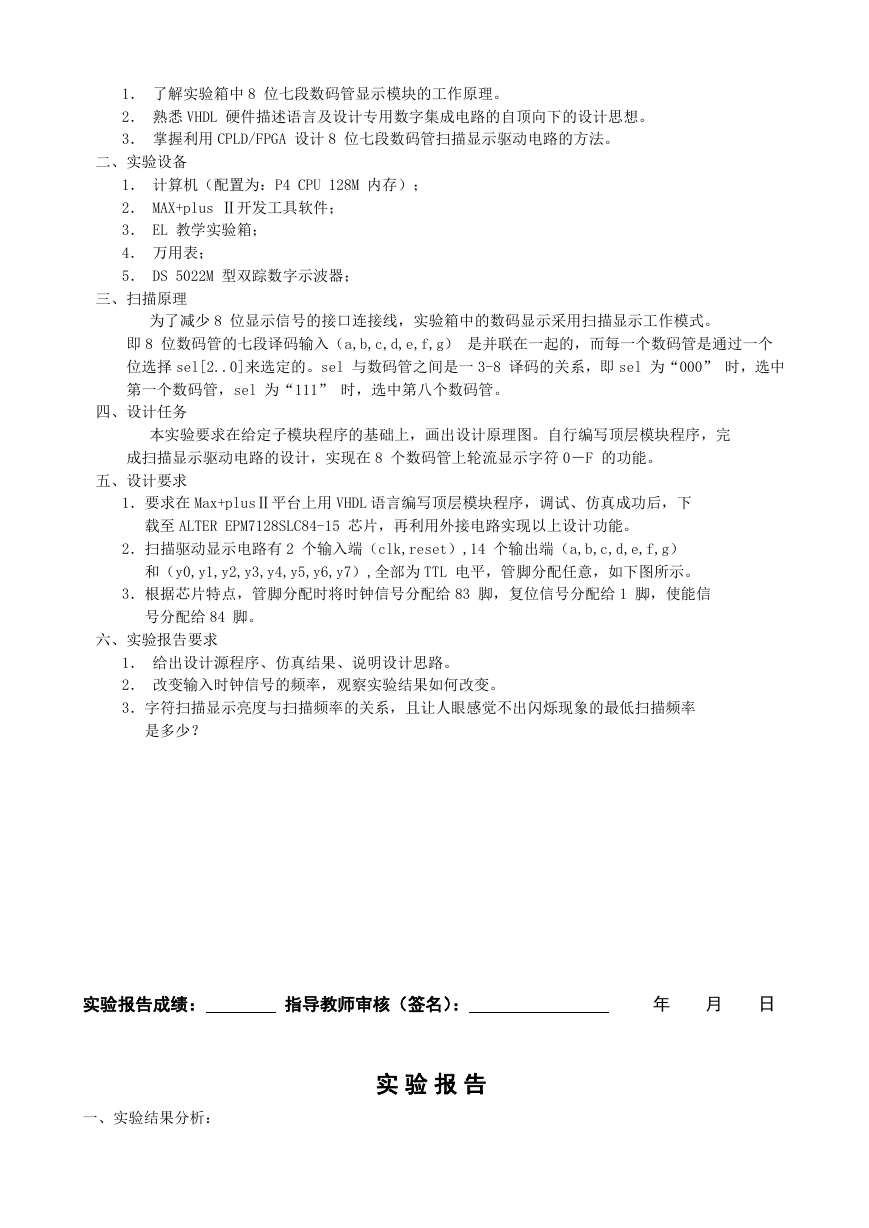
和(y0,y1,y2,y3,y4,y5,y6,y7),全部为 TTL 电平,管脚分配任意,如下图所示。
3.根据芯片特点,管脚分配时将时钟信号分配给 83 脚,复位信号分配给 1 脚,使能信
号分配给 84 脚。
六、实验报告要求
1. 给出设计源程序、仿真结果、说明设计思路。
2. 改变输入时钟信号的频率,观察实验结果如何改变。
3.字符扫描显示亮度与扫描频率的关系,且让人眼感觉不出闪烁现象的最低扫描频率
是多少?
实验报告成绩:
指导教师审核(签名):
年
月 日
一、实验结果分析:
实 验 报 告
�
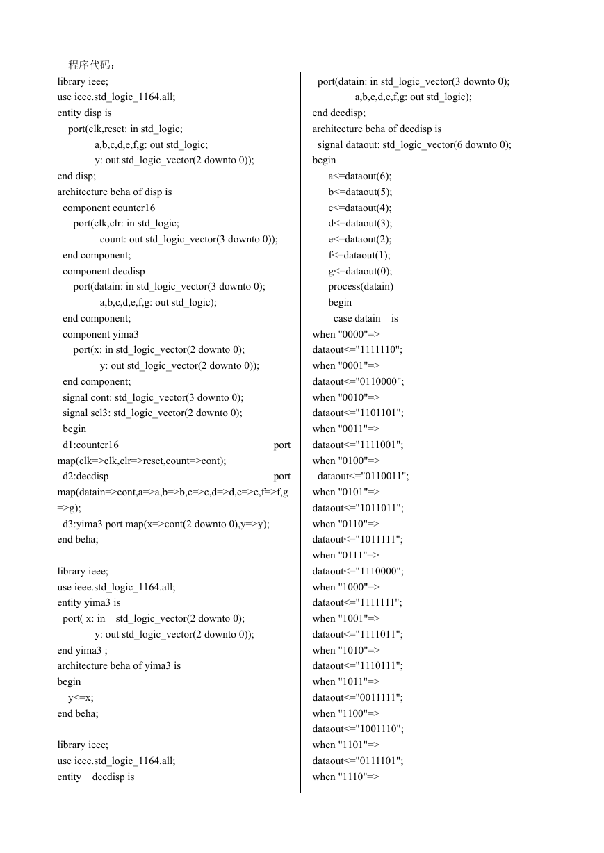
程序代码:
library ieee;
use ieee.std_logic_1164.all;
entity disp is
port(clk,reset: in std_logic;
a,b,c,d,e,f,g: out std_logic;
y: out std_logic_vector(2 downto 0));
end disp;
architecture beha of disp is
component counter16
port(clk,clr: in std_logic;
count: out std_logic_vector(3 downto 0));
end component;
component decdisp
port(datain: in std_logic_vector(3 downto 0);
a,b,c,d,e,f,g: out std_logic);
end component;
component yima3
port(x: in std_logic_vector(2 downto 0);
y: out std_logic_vector(2 downto 0));
end component;
signal cont: std_logic_vector(3 downto 0);
signal sel3: std_logic_vector(2 downto 0);
begin
d1:counter16
map(clk=>clk,clr=>reset,count=>cont);
port
d2:decdisp
map(datain=>cont,a=>a,b=>b,c=>c,d=>d,e=>e,f=>f,g
=>g);
d3:yima3 port map(x=>cont(2 downto 0),y=>y);
end beha;
port
library ieee;
use ieee.std_logic_1164.all;
entity yima3 is
port( x: in
std_logic_vector(2 downto 0);
y: out std_logic_vector(2 downto 0));
end yima3 ;
architecture beha of yima3 is
begin
y<=x;
end beha;
library ieee;
use ieee.std_logic_1164.all;
entity
decdisp is
port(datain: in std_logic_vector(3 downto 0);
a,b,c,d,e,f,g: out std_logic);
end decdisp;
architecture beha of decdisp is
signal dataout: std_logic_vector(6 downto 0);
begin
is
a<=dataout(6);
b<=dataout(5);
c<=dataout(4);
d<=dataout(3);
e<=dataout(2);
f<=dataout(1);
g<=dataout(0);
process(datain)
begin
case datain
when "0000"=>
dataout<="1111110";
when "0001"=>
dataout<="0110000";
when "0010"=>
dataout<="1101101";
when "0011"=>
dataout<="1111001";
when "0100"=>
dataout<="0110011";
when "0101"=>
dataout<="1011011";
when "0110"=>
dataout<="1011111";
when "0111"=>
dataout<="1110000";
when "1000"=>
dataout<="1111111";
when "1001"=>
dataout<="1111011";
when "1010"=>
dataout<="1110111";
when "1011"=>
dataout<="0011111";
when "1100"=>
dataout<="1001110";
when "1101"=>
dataout<="0111101";
when "1110"=>
�
dataout<="1001111";
when "1111"=>
dataout<="1000111";
when others=>
dataout<="XXXXXXX";
end case;
end process;
end beha;
library ieee;
use ieee.std_logic_1164.all;
use ieee.std_logic_unsigned.all;
entity counter16 is
port(clk,clr: in std_logic;
count: out std_logic_vector(3 downto 0);
sel: out std_logic_vector(2 downto 0));
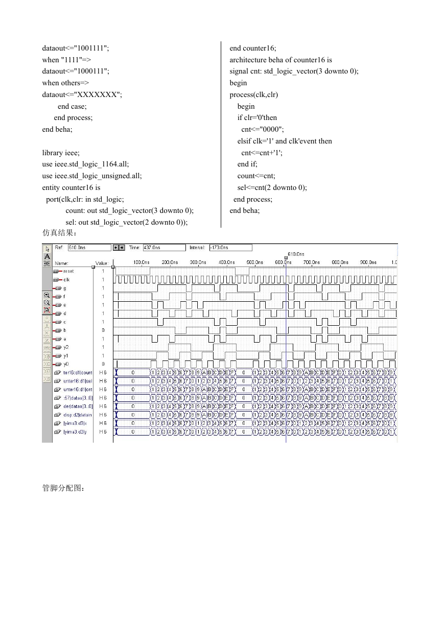
仿真结果:
end counter16;
architecture beha of counter16 is
signal cnt: std_logic_vector(3 downto 0);
begin
process(clk,clr)
begin
if clr='0'then
cnt<="0000";
elsif clk='1' and clk'event then
cnt<=cnt+'1';
end if;
count<=cnt;
sel<=cnt(2 downto 0);
end process;
end beha;
管脚分配图:
�
二、实验心得体会
做完 EDA 实验,我感到受益匪浅。这不仅使我了解了 EDA 的实验系统,学习了 MAX+PLUSⅡ软件
的使用,掌握了基本的电路设计流程、方法以及技巧,更增强了我对 EDA 设计的兴趣。
在实验的过程中,老师又结合实际详细的教了我们 VHDL 语言的基本指令及编程方法,教我们熟悉了在
PC 机上运用 MAX+PLUSⅡ软件和 EPLD 进行电路设计的设计和仿真过程。
之后,老师为我们布置了实验任务,开始,大家都不会编写程序,或是编出来的程序有很多错误,但
是在老师的指导修改下,我们克服了困难,找到了问题所在,改正了错误,编出了正确的程序。但在软
件使用及仿真的时候,大家都遇到了较大的困难,同学们都是第一次接触软件,而且软件都是纯英文,
加上不熟悉使用流程,老师为我们了讲了使用方法之后大家还是不太懂,后来在同学们的互相讨论中,
及个别问题请教老师后,终于也攻克了这一难关,得到了完美的仿真波形和结果。
具备这些基本知识,相信为我今后的自主学习奠定了良好的基础。
�


 2023年江西萍乡中考道德与法治真题及答案.doc
 2012年重庆南川中考生物真题及答案.doc
 2013年江西师范大学地理学综合及文艺理论基础考研真题.doc
 2020年四川甘孜小升初语文真题及答案I卷.doc
 2020年注册岩土工程师专业基础考试真题及答案.doc
 2023-2024学年福建省厦门市九年级上学期数学月考试题及答案.doc
 2021-2022学年辽宁省沈阳市大东区九年级上学期语文期末试题及答案.doc
 2022-2023学年北京东城区初三第一学期物理期末试卷及答案.doc
 2018上半年江西教师资格初中地理学科知识与教学能力真题及答案.doc
 2012年河北国家公务员申论考试真题及答案-省级.doc
 2020-2021学年江苏省扬州市江都区邵樊片九年级上学期数学第一次质量检测试题及答案.doc
 2022下半年黑龙江教师资格证中学综合素质真题及答案.doc