logo资料库

Intel主板-AP440FX说明书.pdf

第1页 / 共74页
第2页 / 共74页
第3页 / 共74页
第4页 / 共74页
第5页 / 共74页
第6页 / 共74页
第7页 / 共74页
第8页 / 共74页
资料共74页,剩余部分请下载后查看
AP440FX Motherboard Technical Product Specification
Revision History
Table of Contents
1 Motherboard Description
1.1 Overview
1.2 Motherboard Manufacturing Options
1.3 Form Factor
1.4 I/O Shield
1.5 Microprocessor
1.5.1 Microprocessor Upgrade
1.5.2 Microprocessor Heatsink and Clips
1.6 Main System Memory
1.6.1 DRAM
1.6.2 Parity and ECC DRAM
1.7 Chipset
1.7.1 82441FX PCI Bridge and Memory Controller (PMC)
1.7.2 82442FX Data Bus Accelerator (DBX)
1.7.3 82371SB PCI/ISA IDE Xccelerator (PIIX3)
1.7.4 IDE Support
1.7.5 Secure Flash Support
1.7.6 USB Support
1.8 PC87307 Super I/O Controller
1.8.1 Floppy Controller
1.8.2 Keyboard and Mouse Interface
1.8.3 Real-Time Clock, CMOS RAM and Battery
1.8.4 Infrared Support
1.8.5 Parallel Port
1.9 Graphics Subsystem
1.9.1 S3 ViRGE Graphics Subsystem
1.9.2 S3 ViRGE/DX Graphics Subsystem
1.9.3 LBP VESA Feature Connector
1.9.4 Graphics Drivers and Utilities
1.10 Audio Subsystem
1.11 Management Extension Hardware
1.12 Motherboard Connectors
1.12.1 Front Panel Connectors
1.12.2 Memory/Expansion Connectors
1.12.3 VESA Feature Connector
1.12.4 Serial Header
1.12.5 Audio Connectors
1.12.6 Power Supply Connectors
1.12.7 Floppy/IDE Connectors
1.12.8 Back Panel Connectors
1.13 Jumper Settings
1.13.1 Microprocessor Configuration (J4L2)
1.13.2 Motherboard Configuration (J4L2, J1J1)
1.14 Reliability
1.15 Environmental
1.16 Power Consumption
1.16.1 Power Supply Considerations
1.17 Regulatory Compliance
1.17.1 Safety
1.17.2 EMI
1.17.3 Product Certification Markings
2 Motherboard Resources
2.1 Memory Map
2.2 I/O Map
2.3 Soft-Off Control
2.4 PCI Configuration Space Map
2.5 DMA Channels
2.6 Interrupts
3 Motherboard BIOS and Setup Utility
3.1 Introduction
3.2 BIOS Flash Memory Organization
3.3 BIOS Upgrades
3.4 PCI IDE Support
3.5 PCI Auto-Configuration
3.6 ISA Plug and Play
3.7 Desktop Management Interface (DMI)
3.8 Advanced Power Management (APM)
3.9 Advanced Power Control (APC)
3.10 Language Support
3.11 Boot Options
3.12 Flash LOGO Area
3.13 Setup Enable Jumper
3.14 Overview of the Setup Menu Screens
3.14.1 Main BIOS Setup Screen
3.14.2 Floppy Options Subscreen
3.14.3 IDE Device Configuration Subscreen
3.14.4 Boot Options Subscreen
3.14.5 Advanced Screen
3.14.6 Event Logging Configuration
3.14.7 Peripheral Configuration Subscreen
3.14.8 Advanced Chipset Configuration Subscreen
3.14.9 Power Management Configuration Subscreen
3.14.10 Plug and Play Configuration Subscreen
3.14.11 Event Logging Configuration
3.14.12 Security Screen
3.14.13 Security Screen Options
3.14.14 Exit Screen
4 Error Messages and Beep Codes
4.1 BIOS Beep Codes
4.2 PCI Configuration Error Messages
4.3 BIOS Error Messages
4.4 ISA NMI Messages
AP440FX Motherboard Technical Product Specification The AP440FX motherboard may contain design defects or errors known as errata which may cause the product to deviate from published specifications. Current characterized errata are documented in the AP440FX Motherboard Specification Update. May, 1997 Order Number 281830-002
Revision History Revision -001 -002 Revision History Release of the AP440FX Technical Product Specification. Second release of the AP440FX Technical Product Specification Date 7/96 5/97 This product specification applies only to standard AP440FX motherboards with BIOS identifier 1.00.0x.CT1. Changes to this specification will be published in the AP440FX Motherboard Specification Update (Order Number: 281831) before being incorporated into a revision of this document. Information in this document is provided in connection with Intel products. No license, express or implied, by estoppel or otherwise, to any intellectual property rights is granted by this document. Except as provided in Intel's Terms and Conditions of Sale for such products, Intel assumes no liability whatsoever, and Intel disclaims any express or implied warranty, relating to sale and/or use of Intel products including liability or warranties relating to fitness for a particular purpose, merchantability, or infringement of any patent, copyright or other intellectual property right. Intel products are not intended for use in medical, life saving, or life sustaining applications. Intel retains the right to make changes to specifications and product descriptions at any time, without notice. The AP440FX motherboard may contain design defects or errors known as errata which may cause the product to deviate from published specifications. Current characterized errata are available on request. Contact your local Intel sales office or your distributor to obtain the latest specifications and before placing your product order. Copies of documents which have an ordering number and are referenced in this document, or other Intel literature, may be obtained from: Intel Corporation P.O. Box 7641 Mt. Prospect IL 60056-764 or call 1-800-879-4683 or call in North America 1-800-879-4683, Europe 44-0-1793-431-155, France 44-0-1793-421-777, Germany 44-0-1793-421-333, other Countries 708-296-9333. † Third-party brands and names are the property of their respective owners. Copyright Intel Corporation, 1996-1997.
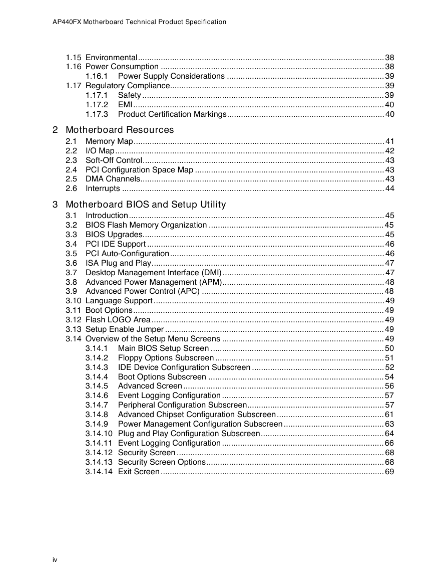
Table of Contents 1 Motherboard Description 1.5.1 1.5.2 1.8.1 1.8.2 1.8.3 1.8.4 1.8.5 1.9.1 1.9.2 1.9.3 1.9.4 1.6.1 1.6.2 1.7.1 1.7.2 1.7.3 1.7.4 1.7.5 1.7.6 1.1 Overview...................................................................................................................... 7 1.2 Motherboard Manufacturing Options ........................................................................... 9 1.3 Form Factor ................................................................................................................. 9 1.4 I/O Shield................................................................................................................... 10 1.5 Microprocessor .......................................................................................................... 11 Microprocessor Upgrade ............................................................................. 11 Microprocessor Heatsink and Clips ............................................................. 11 1.6 Main System Memory ................................................................................................ 12 DRAM.......................................................................................................... 12 Parity and ECC DRAM ................................................................................ 12 1.7 Chipset ...................................................................................................................... 12 82441FX PCI Bridge and Memory Controller (PMC) ................................... 12 82442FX Data Bus Accelerator (DBX) ........................................................ 13 82371SB PCI/ISA IDE Xccelerator (PIIX3).................................................. 13 IDE Support................................................................................................. 14 Secure Flash Support.................................................................................. 14 USB Support ............................................................................................... 14 1.8 PC87307 Super I/O Controller................................................................................... 15 Floppy Controller ......................................................................................... 15 Keyboard and Mouse Interface ................................................................... 15 Real-Time Clock, CMOS RAM and Battery ................................................. 16 Infrared Support .......................................................................................... 16 Parallel Port................................................................................................. 16 1.9 Graphics Subsystem.................................................................................................. 16 S3 ViRGE Graphics Subsystem .................................................................. 17 S3 ViRGE/DX Graphics Subsystem ............................................................ 18 LBP VESA Feature Connector .................................................................... 18 Graphics Drivers and Utilities ...................................................................... 18 1.10 Audio Subsystem....................................................................................................... 19 1.11 Management Extension Hardware............................................................................. 19 1.12 Motherboard Connectors ........................................................................................... 20 1.12.1 Front Panel Connectors............................................................................... 22 1.12.2 Memory/Expansion Connectors................................................................... 25 1.12.3 VESA Feature Connector............................................................................ 27 1.12.4 Serial Header .............................................................................................. 27 1.12.5 Audio Connectors........................................................................................ 28 1.12.6 Power Supply Connectors ........................................................................... 29 1.12.7 Floppy/IDE Connectors ............................................................................... 30 1.12.8 Back Panel Connectors............................................................................... 32 1.13 Jumper Settings......................................................................................................... 35 1.13.1 Microprocessor Configuration (J4L2)........................................................... 36 1.13.2 Motherboard Configuration (J4L2, J1J1) ..................................................... 36 1.14 Reliability ................................................................................................................... 37 iii
AP440FX Motherboard Technical Product Specification 1.15 Environmental............................................................................................................ 38 1.16 Power Consumption .................................................................................................. 38 1.16.1 Power Supply Considerations ..................................................................... 39 1.17 Regulatory Compliance.............................................................................................. 39 1.17.1 Safety .......................................................................................................... 39 1.17.2 EMI.............................................................................................................. 40 1.17.3 Product Certification Markings..................................................................... 40 2 Motherboard Resources 2.1 Memory Map.............................................................................................................. 41 2.2 I/O Map...................................................................................................................... 42 2.3 Soft-Off Control.......................................................................................................... 43 2.4 PCI Configuration Space Map ................................................................................... 43 2.5 DMA Channels........................................................................................................... 43 2.6 Interrupts ................................................................................................................... 44 3 Motherboard BIOS and Setup Utility 3.1 Introduction................................................................................................................ 45 3.2 BIOS Flash Memory Organization ............................................................................. 45 3.3 BIOS Upgrades.......................................................................................................... 45 3.4 PCI IDE Support ........................................................................................................ 46 3.5 PCI Auto-Configuration.............................................................................................. 46 3.6 ISA Plug and Play...................................................................................................... 47 3.7 Desktop Management Interface (DMI)....................................................................... 47 3.8 Advanced Power Management (APM)....................................................................... 48 3.9 Advanced Power Control (APC) ................................................................................ 48 3.10 Language Support ..................................................................................................... 49 3.11 Boot Options.............................................................................................................. 49 3.12 Flash LOGO Area ...................................................................................................... 49 3.13 Setup Enable Jumper ................................................................................................ 49 3.14 Overview of the Setup Menu Screens ....................................................................... 49 3.14.1 Main BIOS Setup Screen ............................................................................ 50 Floppy Options Subscreen .......................................................................... 51 3.14.2 3.14.3 IDE Device Configuration Subscreen .......................................................... 52 3.14.4 Boot Options Subscreen ............................................................................. 54 3.14.5 Advanced Screen ........................................................................................ 56 3.14.6 Event Logging Configuration ....................................................................... 57 3.14.7 Peripheral Configuration Subscreen............................................................ 57 3.14.8 Advanced Chipset Configuration Subscreen............................................... 61 3.14.9 Power Management Configuration Subscreen ............................................ 63 3.14.10 Plug and Play Configuration Subscreen...................................................... 64 3.14.11 Event Logging Configuration ....................................................................... 66 3.14.12 Security Screen ........................................................................................... 68 3.14.13 Security Screen Options.............................................................................. 68 3.14.14 Exit Screen .................................................................................................. 69 iv
Contents 4 Error Messages and Beep Codes 4.1 BIOS Beep Codes ..................................................................................................... 71 4.2 PCI Configuration Error Messages ............................................................................ 71 4.3 BIOS Error Messages................................................................................................ 73 4.4 ISA NMI Messages .................................................................................................... 74 Figures 1. Motherboard Features ................................................................................................. 8 2. Motherboard Dimensions............................................................................................. 9 3. Back Panel I/O Shield Dimensions ............................................................................ 10 4. Motherboard Connector Locations............................................................................. 21 5. Front Panel I/O Connectors ....................................................................................... 22 Fan Connector Usage................................................................................................ 24 6. I/O Connections......................................................................................................... 32 7. 8. Jumper Locations ...................................................................................................... 35 Tables Key to Motherboard Features ...................................................................................... 8 1. S3 ViRGE Supported Resolutions ............................................................................. 17 2. S3 ViRGE/DX Supported Resolutions ....................................................................... 18 3. Front Panel I/O Connector (J2A1) ............................................................................. 22 4. Keylock Connector (J3A1) ......................................................................................... 24 5. Auxiliary Fan Connector (J4A1) ................................................................................. 24 6. PCI/ISA Riser Connector (J6J2) ................................................................................ 25 7. LBP VESA Feature Connector (J1K1) ....................................................................... 27 8. 9. Serial Port (COM2H, J3N1) Pinout ............................................................................ 27 10. CD-ROM Connector (J9N1) ....................................................................................... 28 11. Wavetable Upgrade Connector (J9L1) ...................................................................... 28 12. Telephony Connector (J9K1)..................................................................................... 28 13. Primary Power Supply Connector (J9H1) .................................................................. 29 14. External 3.3 V Power Supply Connector (J9J1)........................................................ 29 15. Soft-Off Power Supply Connector (J9F1)................................................................... 30 16. Floppy Drive Connector (J8L1) .................................................................................. 30 17. IDE Connectors (J8H1, J9H2) ................................................................................... 31 18. VGA Video Connector (J1N1).................................................................................... 32 19. Serial Port Connector Pinout ..................................................................................... 33 20. USB Connector Pinout............................................................................................... 33 21. PS/2 Keyboard/Mouse Connector Pinout .................................................................. 33 22. Parallel Port Connector Pinout................................................................................... 34 23. Microprocessor/System Speed Settings .................................................................... 36 24. Configuration Jumper Settings................................................................................... 37 25. Motherboard Environmental Specifications................................................................ 38 26. Power Usage ............................................................................................................. 38 27. DC Voltage ................................................................................................................ 39 28. Memory Map.............................................................................................................. 41 29. I/O Map...................................................................................................................... 42 30. PCI Configuration Space Map ................................................................................... 43 31. DMA Channels........................................................................................................... 43 v
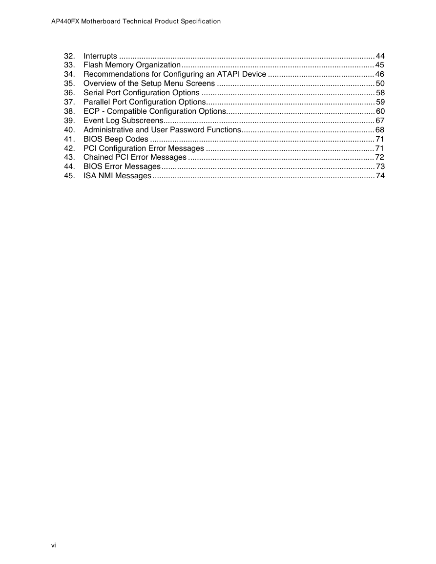
AP440FX Motherboard Technical Product Specification Interrupts ................................................................................................................... 44 32. 33. Flash Memory Organization....................................................................................... 45 34. Recommendations for Configuring an ATAPI Device ................................................ 46 35. Overview of the Setup Menu Screens ....................................................................... 50 36. Serial Port Configuration Options .............................................................................. 58 37. Parallel Port Configuration Options............................................................................ 59 38. ECP - Compatible Configuration Options................................................................... 60 39. Event Log Subscreens............................................................................................... 67 40. Administrative and User Password Functions............................................................ 68 41. BIOS Beep Codes ..................................................................................................... 71 42. PCI Configuration Error Messages ............................................................................ 71 43. Chained PCI Error Messages .................................................................................... 72 44. BIOS Error Messages................................................................................................ 73 ISA NMI Messages .................................................................................................... 74 45. vi
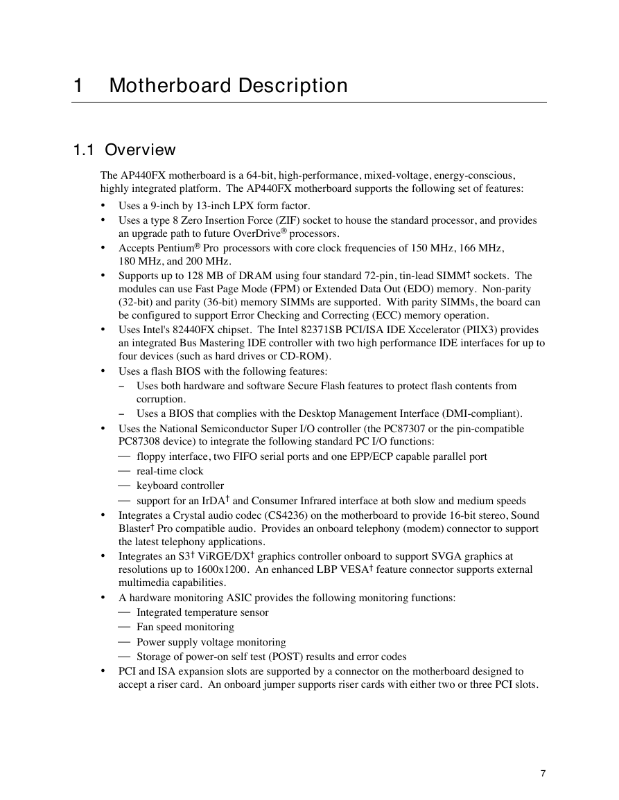
1 Motherboard Description 1.1 Overview The AP440FX motherboard is a 64-bit, high-performance, mixed-voltage, energy-conscious, highly integrated platform. The AP440FX motherboard supports the following set of features: • Uses a 9-inch by 13-inch LPX form factor. • Uses a type 8 Zero Insertion Force (ZIF) socket to house the standard processor, and provides an upgrade path to future OverDrive® processors. • Accepts Pentium® Pro processors with core clock frequencies of 150 MHz, 166 MHz, 180 MHz, and 200 MHz. • Supports up to 128 MB of DRAM using four standard 72-pin, tin-lead SIMM† sockets. The modules can use Fast Page Mode (FPM) or Extended Data Out (EDO) memory. Non-parity (32-bit) and parity (36-bit) memory SIMMs are supported. With parity SIMMs, the board can be configured to support Error Checking and Correcting (ECC) memory operation. • Uses Intel's 82440FX chipset. The Intel 82371SB PCI/ISA IDE Xccelerator (PIIX3) provides an integrated Bus Mastering IDE controller with two high performance IDE interfaces for up to four devices (such as hard drives or CD-ROM). • Uses a flash BIOS with the following features: - Uses both hardware and software Secure Flash features to protect flash contents from corruption. - Uses a BIOS that complies with the Desktop Management Interface (DMI-compliant). • Uses the National Semiconductor Super I/O controller (the PC87307 or the pin-compatible floppy interface, two FIFO serial ports and one EPP/ECP capable parallel port real-time clock keyboard controller support for an IrDA† and Consumer Infrared interface at both slow and medium speeds PC87308 device) to integrate the following standard PC I/O functions: Integrates a Crystal audio codec (CS4236) on the motherboard to provide 16-bit stereo, Sound Blaster† Pro compatible audio. Provides an onboard telephony (modem) connector to support the latest telephony applications. Integrates an S3† ViRGE/DX† graphics controller onboard to support SVGA graphics at resolutions up to 1600x1200. An enhanced LBP VESA† feature connector supports external multimedia capabilities. • • • A hardware monitoring ASIC provides the following monitoring functions: Integrated temperature sensor Fan speed monitoring Power supply voltage monitoring Storage of power-on self test (POST) results and error codes • PCI and ISA expansion slots are supported by a connector on the motherboard designed to accept a riser card. An onboard jumper supports riser cards with either two or three PCI slots. 7
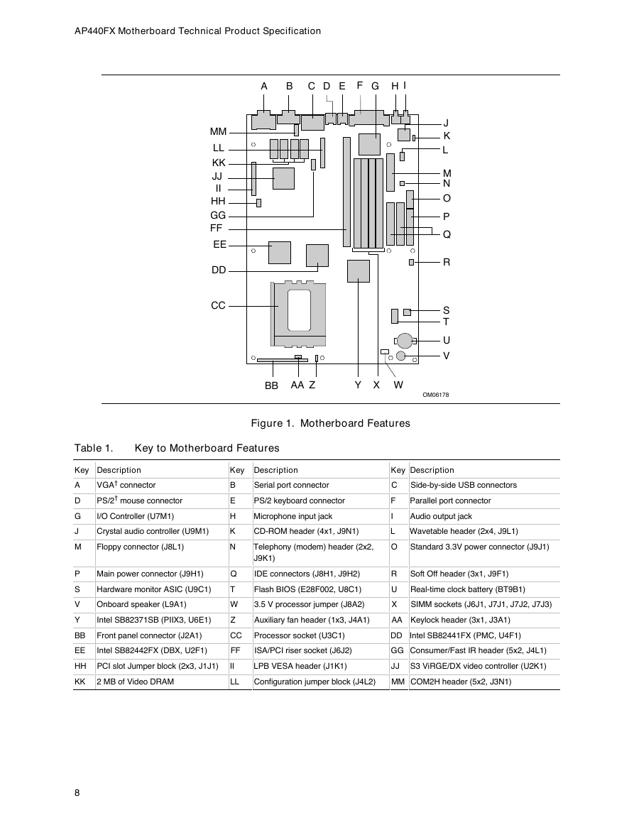
AP440FX Motherboard Technical Product Specification A B C D E F G H I MM LL KK JJ II HH GG FF EE DD CC J K L M N O P Q R S T U V BB AA Z Y X W OM06178 Figure 1. Motherboard Features Table 1. Key to Motherboard Features Key Description Key Description Key Description A D G J M P S V Y BB EE VGA† connector PS/2† mouse connector I/O Controller (U7M1) Crystal audio controller (U9M1) Floppy connector (J8L1) Main power connector (J9H1) Hardware monitor ASIC (U9C1) Onboard speaker (L9A1) Intel SB82371SB (PIIX3, U6E1) Front panel connector (J2A1) Intel SB82442FX (DBX, U2F1) HH PCI slot Jumper block (2x3, J1J1) KK 2 MB of Video DRAM B E H K N Q T W Z CC FF II LL Serial port connector PS/2 keyboard connector Microphone input jack C F I Side-by-side USB connectors Parallel port connector Audio output jack CD-ROM header (4x1, J9N1) L Wavetable header (2x4, J9L1) Telephony (modem) header (2x2, J9K1) O Standard 3.3V power connector (J9J1) IDE connectors (J8H1, J9H2) Flash BIOS (E28F002, U8C1) 3.5 V processor jumper (J8A2) R U X Soft Off header (3x1, J9F1) Real-time clock battery (BT9B1) SIMM sockets (J6J1, J7J1, J7J2, J7J3) Auxiliary fan header (1x3, J4A1) AA Keylock header (3x1, J3A1) Processor socket (U3C1) DD Intel SB82441FX (PMC, U4F1) ISA/PCI riser socket (J6J2) GG Consumer/Fast IR header (5x2, J4L1) LPB VESA header (J1K1) JJ S3 ViRGE/DX video controller (U2K1) Configuration jumper block (J4L2) MM COM2H header (5x2, J3N1) 8
分享到:
收藏