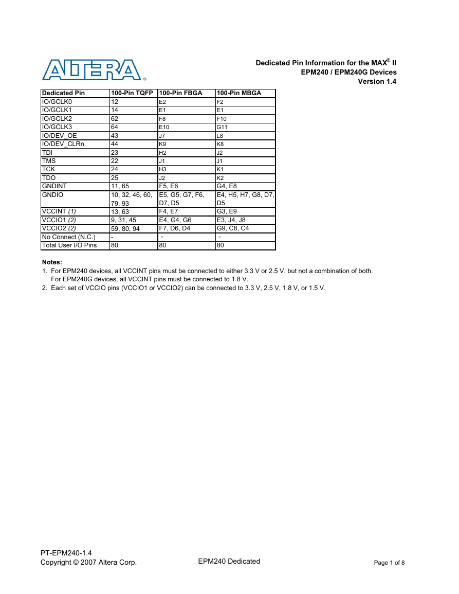
Dedicated Pin Information for the MAX® II
EPM240 / EPM240G Devices
Version 1.4
Dedicated Pin
IO/GCLK0
IO/GCLK1
IO/GCLK2
IO/GCLK3
IO/DEV_OE
IO/DEV_CLRn
TDI
TMS
TCK
TDO
GNDINT
GNDIO
VCCINT (1)
VCCIO1 (2)
VCCIO2 (2)
No Connect (N.C.)
Total User I/O Pins
100-Pin TQFP 100-Pin FBGA
12
14
62
64
43
44
23
22
24
25
11, 65
10, 32, 46, 60,
79, 93
13, 63
9, 31, 45
59, 80, 94
-
80
E2
E1
F8
E10
J7
K9
H2
J1
H3
J2
F5, E6
E5, G5, G7, F6,
D7, D5
F4, E7
E4, G4, G6
F7, D6, D4
-
80
100-Pin MBGA
F2
E1
F10
G11
L8
K8
J2
J1
K1
K2
G4, E8
E4, H5, H7, G8, D7,
D5
G3, E9
E3, J4, J8
G9, C8, C4
-
80
Notes:
1. For EPM240 devices, all VCCINT pins must be connected to either 3.3 V or 2.5 V, but not a combination of both.
For EPM240G devices, all VCCINT pins must be connected to 1.8 V.
2. Each set of VCCIO pins (VCCIO1 or VCCIO2) can be connected to 3.3 V, 2.5 V, 1.8 V, or 1.5 V.
PT-EPM240-1.4
Copyright © 2007 Altera Corp.
EPM240 Dedicated
Page 1 of 8�
Optional
Function(s)
GCLK0
GCLK1
DEV_OE
DEV_CLRn
Bank
Number
B1
B1
B1
B1
B1
B1
B1
B1
B1
B1
B1
B1
B1
B1
B1
B1
B1
B1
B1
B1
B1
B1
B1
B1
B1
B1
B1
B1
B1
B1
B1
B1
B1
B1
B1
B1
B1
B1
B1
B1
B1
B1
B1
B1
B1
B1
B1
B1
B1
B2
B2
B2
B2
Pad Number
Orientation
0
1
2
3
4
5
6
7
8
9
10
11
12
13
14
15
16
17
18
19
20
21
22
23
24
25
26
27
28
29
30
31
32
33
34
35
36
37
38
39
40
41
42
43
44
45
46
47
48
49
50
51
52
53
54
Pin/Pad
Function
IO
IO
IO
IO
IO
IO
IO
VCCIO1
GNDIO
GNDINT
IO
VCCINT
IO
IO
IO
IO
IO
IO
IO
IO
TMS
TDI
TCK
N.C. (1)
TDO
IO
IO
IO
IO
IO
VCCIO1
GNDIO
IO
IO
IO
IO
IO
IO
IO
IO
IO
IO
IO
IO
VCCIO1
GNDIO
IO
IO
IO
IO
IO
IO
IO
IO
IO
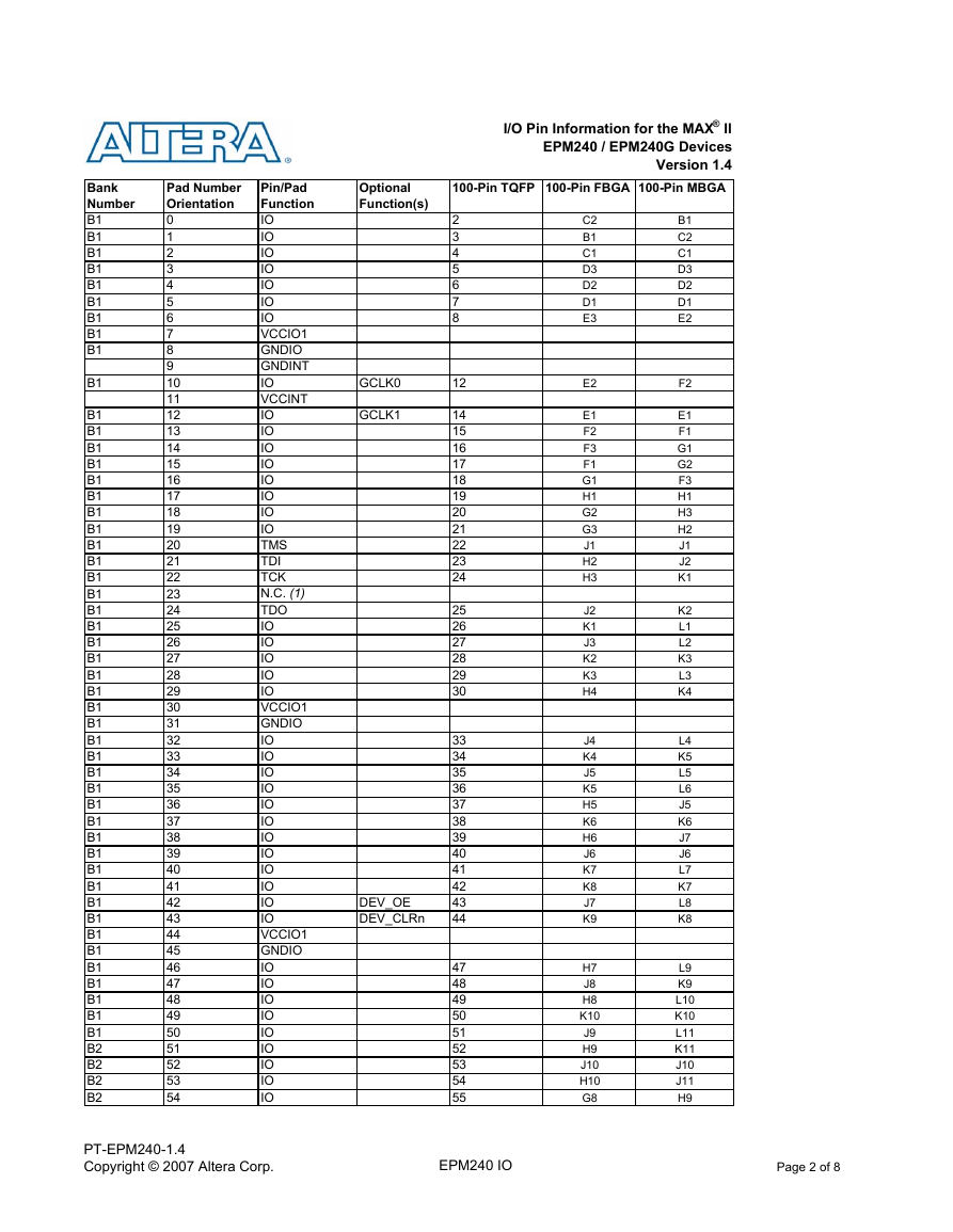
I/O Pin Information for the MAX® II
EPM240 / EPM240G Devices
Version 1.4
100-Pin TQFP 100-Pin FBGA 100-Pin MBGA
2
3
4
5
6
7
8
12
14
15
16
17
18
19
20
21
22
23
24
25
26
27
28
29
30
33
34
35
36
37
38
39
40
41
42
43
44
47
48
49
50
51
52
53
54
55
C2
B1
C1
D3
D2
D1
E3
E2
E1
F2
F3
F1
G1
H1
G2
G3
J1
H2
H3
J2
K1
J3
K2
K3
H4
J4
K4
J5
K5
H5
K6
H6
J6
K7
K8
J7
K9
H7
J8
H8
K10
J9
H9
J10
H10
G8
B1
C2
C1
D3
D2
D1
E2
F2
E1
F1
G1
G2
F3
H1
H3
H2
J1
J2
K1
K2
L1
L2
K3
L3
K4
L4
K5
L5
L6
J5
K6
J7
J6
L7
K7
L8
K8
L9
K9
L10
K10
L11
K11
J10
J11
H9
PT-EPM240-1.4
Copyright © 2007 Altera Corp.
EPM240 IO
Page 2 of 8�
Optional
Function(s)
GCLK2
GCLK3
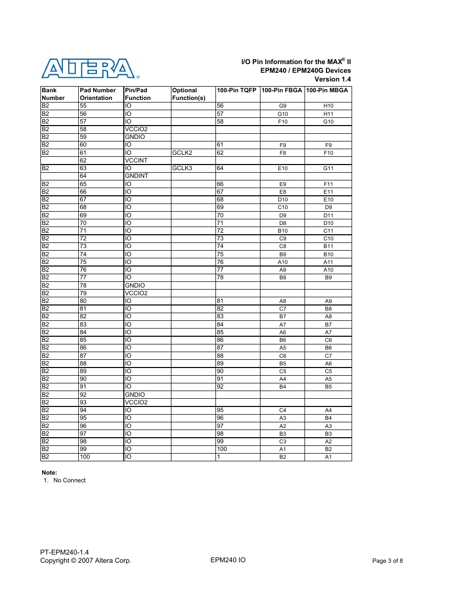
I/O Pin Information for the MAX® II
EPM240 / EPM240G Devices
Version 1.4
100-Pin TQFP 100-Pin FBGA 100-Pin MBGA
56
57
58
61
62
64
66
67
68
69
70
71
72
73
74
75
76
77
78
81
82
83
84
85
86
87
88
89
90
91
92
95
96
97
98
99
100
1
G9
G10
F10
F9
F8
E10
E9
E8
D10
C10
D9
D8
B10
C9
C8
B9
A10
A9
B8
A8
C7
B7
A7
A6
B6
A5
C6
B5
C5
A4
B4
C4
A3
A2
B3
C3
A1
B2
H10
H11
G10
F9
F10
G11
F11
E11
E10
D9
D11
D10
C11
C10
B11
B10
A11
A10
B9
A9
B8
A8
B7
A7
C6
B6
C7
A6
C5
A5
B5
A4
B4
A3
B3
A2
B2
A1
Bank
Number
B2
B2
B2
B2
B2
B2
B2
B2
B2
B2
B2
B2
B2
B2
B2
B2
B2
B2
B2
B2
B2
B2
B2
B2
B2
B2
B2
B2
B2
B2
B2
B2
B2
B2
B2
B2
B2
B2
B2
B2
B2
B2
B2
B2
Pad Number
Orientation
55
56
57
58
59
60
61
62
63
64
65
66
67
68
69
70
71
72
73
74
75
76
77
78
79
80
81
82
83
84
85
86
87
88
89
90
91
92
93
94
95
96
97
98
99
100
Pin/Pad
Function
IO
IO
IO
VCCIO2
GNDIO
IO
IO
VCCINT
IO
GNDINT
IO
IO
IO
IO
IO
IO
IO
IO
IO
IO
IO
IO
IO
GNDIO
VCCIO2
IO
IO
IO
IO
IO
IO
IO
IO
IO
IO
IO
IO
GNDIO
VCCIO2
IO
IO
IO
IO
IO
IO
IO
Note:
1. No Connect
PT-EPM240-1.4
Copyright © 2007 Altera Corp.
EPM240 IO
Page 3 of 8�
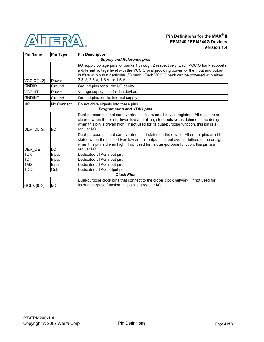
Pin Definitions for the MAX® II
EPM240 / EPM240G Devices
Version 1.4
Pin Name
Pin Type
Pin Description
Supply and Reference pins
VCCIO[1..2]
GNDIO
VCCINT
GNDINT
NC
Power
Ground
Power
Ground
No Connect
DEV_CLRn
I/O
DEV_OE
TCK
TDI
TMS
TDO
I/O
Input
Input
Input
Output
GCLK [0..3]
I/O
I/O supply voltage pins for banks 1 through 2 respectively. Each VCCIO bank supports
a different voltage level with the VCCIO pins providing power for the input and output
buffers within that particular I/O bank. Each VCCIO bank can be powered with either
3.3 V, 2.5 V, 1.8 V, or 1.5 V.
Ground pins for all the I/O banks.
Voltage supply pins for the device.
Ground pins for the internal supply.
Do not drive signals into these pins.
Programming and JTAG pins
Dual-purpose pin that can override all clears on all device registers. All registers are
cleared when the pin is driven low and all registers behave as defined in the design
when this pin is driven high. If not used for its dual-purpose function, this pin is a
regular I/O.
Dual-purpose pin that can override all tri-states on the device. All output pins are tri-
stated when the pin is driven low and all output pins behave as defined in the design
when this pin is driven high. If not used for its dual-purpose function, this pin is a
regular I/O.
Dedicated JTAG input pin.
Dedicated JTAG input pin.
Dedicated JTAG input pin.
Dedicated JTAG output pin.
Clock Pins
Dual-purpose clock pins that connect to the global clock network. If not used for
its dual-purpose function, this pin is a regular I/O.
PT-EPM240-1.4
Copyright © 2007 Altera Corp.
Pin Definitions
Page 4 of 8�
Package Diagram and Bank Information for the MAX® II
EPM240 / EPM240G Devices
Version 1.4
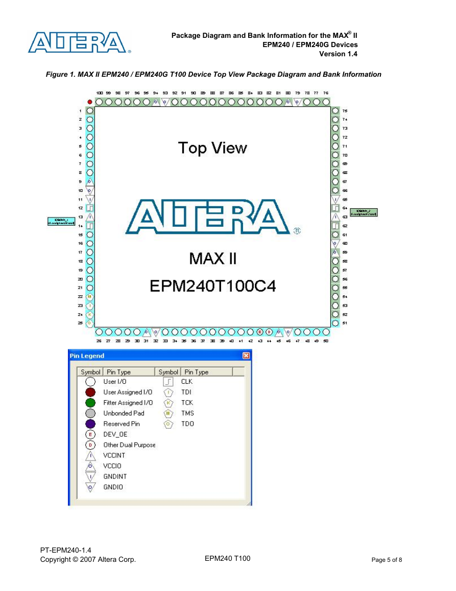
Figure 1. MAX II EPM240 / EPM240G T100 Device Top View Package Diagram and Bank Information
PT-EPM240-1.4
Copyright © 2007 Altera Corp.
EPM240 T100
Page 5 of 8�
Package Diagram and Bank Information for the MAX® II
EPM240 / EPM240G Devices
Version 1.4
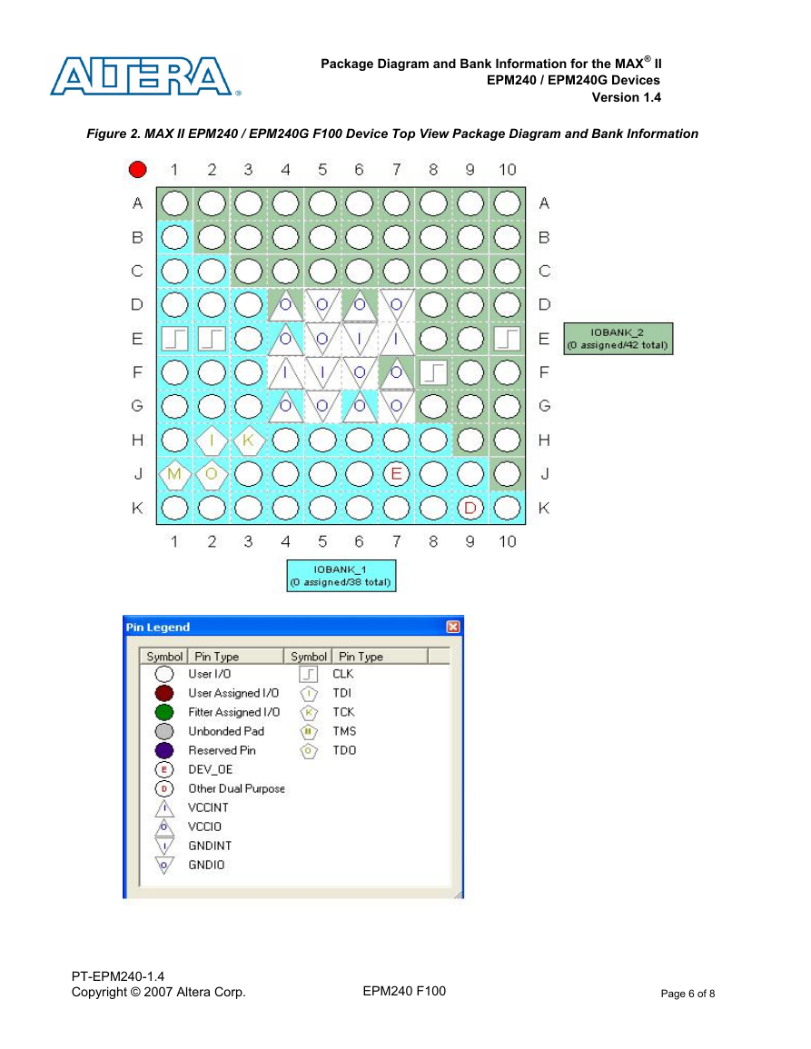
Figure 2. MAX II EPM240 / EPM240G F100 Device Top View Package Diagram and Bank Information
PT-EPM240-1.4
Copyright © 2007 Altera Corp.
EPM240 F100
Page 6 of 8�
Package Diagram and Bank Information for the MAX® II
EPM240 / EPM240G Devices
Version 1.4
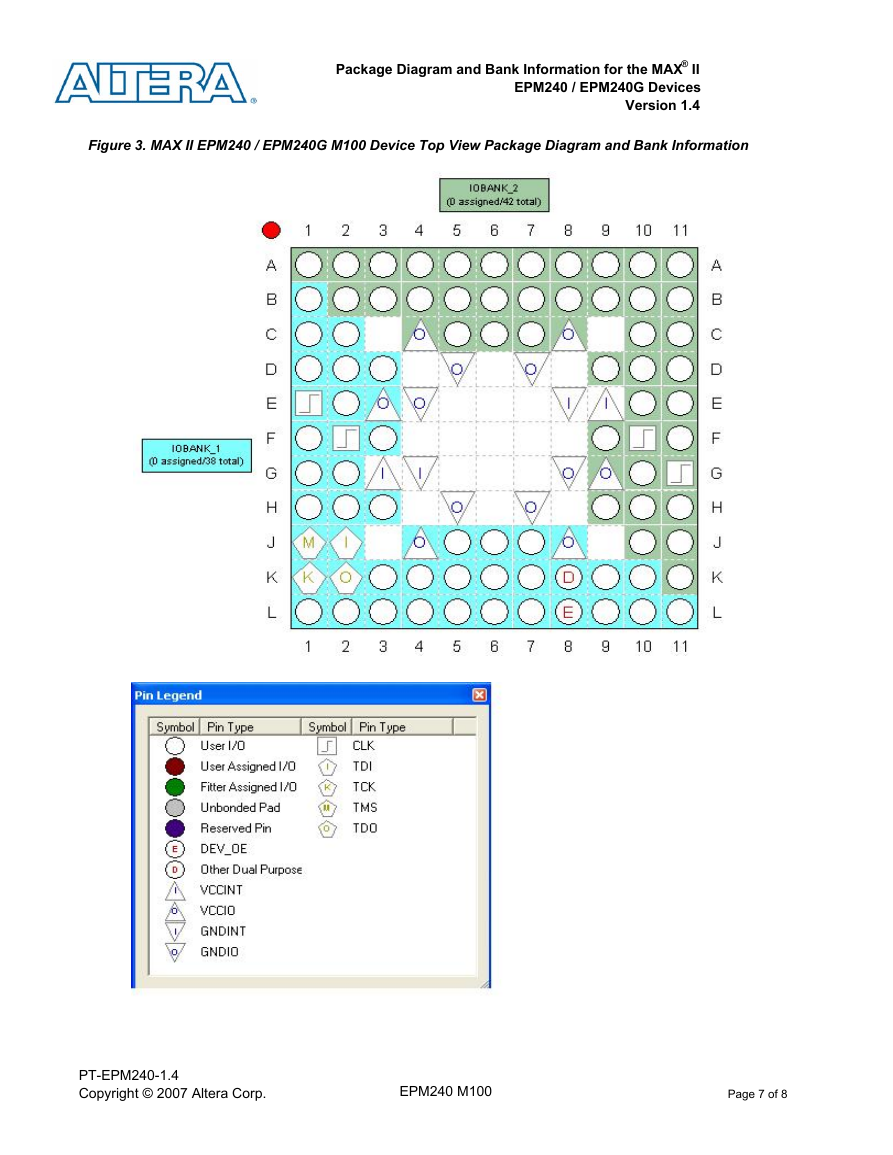
Figure 3. MAX II EPM240 / EPM240G M100 Device Top View Package Diagram and Bank Information
PT-EPM240-1.4
Copyright © 2007 Altera Corp.
EPM240 M100
Page 7 of 8�
Revision History for the MAX® II
EPM240 / EPM240G Devices
Version 1.4
Date
Sep-07
Apr-06
Jan-05
Jul-04
May-04
Version
1.4
1.3
1.2
1.1
1.0
Changes Made
Added support for F100 and M100 packages in the EPM240G device
Added 100-Pin FBGA and 100-Pin MBGA packages
Added MAX IIG device naming to titles, notes, and figures
Added package diagram and bank information figures for each package
Initial release
PT-EPM240-1.4
Copyright © 2007 Altera Corp.
Revision History
Page 8 of 8�


 2023年江西萍乡中考道德与法治真题及答案.doc
 2012年重庆南川中考生物真题及答案.doc
 2013年江西师范大学地理学综合及文艺理论基础考研真题.doc
 2020年四川甘孜小升初语文真题及答案I卷.doc
 2020年注册岩土工程师专业基础考试真题及答案.doc
 2023-2024学年福建省厦门市九年级上学期数学月考试题及答案.doc
 2021-2022学年辽宁省沈阳市大东区九年级上学期语文期末试题及答案.doc
 2022-2023学年北京东城区初三第一学期物理期末试卷及答案.doc
 2018上半年江西教师资格初中地理学科知识与教学能力真题及答案.doc
 2012年河北国家公务员申论考试真题及答案-省级.doc
 2020-2021学年江苏省扬州市江都区邵樊片九年级上学期数学第一次质量检测试题及答案.doc
 2022下半年黑龙江教师资格证中学综合素质真题及答案.doc